


Services on Demand
Article
 English (pdf)
 Article in xml format
 Article references
Indicators

Related links
-
 Cited by Google
 -
 Similars in Google
Share

 Permalink
Journal of the Southern African Institute of Mining and Metallurgy
On-line version ISSN 2411-9717
Print version ISSN 2225-6253
J. S. Afr. Inst. Min. Metall. vol.118 n.5 Johannesburg May. 2018
http://dx.doi.org/10.17159/2411-9717/2018/v118n05a4
PAPERS OF GENERAL INTEREST
Surrounding rock control mechanism in the gob-side retaining entry in thin coal seams, and its application
J.Z. LiI, II; M. ZhangI; Y. LiIII; H. HuI
IAnhui Province Key Laboratory of Mining Reponse and Disaster Prevention, and Control in Deep Coal Mine, Anhui University of Science and Technology, Huainan, Anhui, China
IISchool of Resource and Safety Engineering, Anhui University of Science and Technology, Huainan Anhui, China
IIISchool of Resource and Safety Engineering, China University of Mining and Technology, Beijing, China
SYNOPSIS
The stability of the roadside filling body is the key to successful gob-side entry retention in a thin coal seam. However, the existing failure mechanism of the roadside filling body is unclear, and no proactive measures for the high-stress regulation of the roadway-surrounding rock have been proposed. Taking the 2704N working face of Xinyang mine, China, as an example, this study aimed to elucidate the failure mechanism and characterize the mechanical environment of the roadside filling body in order to implement proactive stress adjustment in gob-side entry retention and measures for the structural control of the surrounding rock. The mode of failure of the roadside filling body was analysed, and numerical simulations and field experiments were subsequently performed to characterize the stress environment of the roadside filling body under caving and gob-filling conditions. Finally, regulatory measures for regional stress were proposed. The results showed that adjusting the three-dimensional stress fields in the surrounding rock causes the majority of the principal deviatoric stress to concentrate on the filling body, thus causing the surrounding rock to fail. Therefore, decreasing the subsidence space of the roof strata and preventing the accumulation of excessive principal deviatoric stress on the roadside filling body are crucial for regulating the regional field stress in gob-side entry retention and structurally controlling the roadway-surrounding rock. After gob filling, neighbouring units in the 'coal-roadside filling body-immediate roof-filling body in the gob' support system jointly form a skeleton structure that supports the overlying rock through contact force. A powerful force chain network is stored in the skeleton structure. The strong force chains in the gob-filling body bear the majority of the stress imparted by the overlying rock. Relative movement between key blocks is restricted because the key blocks compress each other. Thus, the principal deviatoric stress on the roadside filling body decreases and stability is significantly improved. A new technology that combines a mechanized gob-side entry in a thin coal seam and proactive roof guarding in the gob filling behind the hydraulic supports was designed in accordance with the 'green mining' concept of underground separation of coal from gangue and the requirements for pumped filling materials. The results of this study contribute to the theory and technology of gob-side entry retention and provide a basis for an effective stress adjustment and structural control method in the gob-side entry retention area.
Keywords: gob-side entry retention, roadside filling body, failure mechanism, principal deviatoric stress, stress adjustment.
Introduction
Gob-side entry retention can decrease mine driveage ratio and eliminate the adverse effect of stress concentration on coal pillars that support a roadway in a thin coal seam. Gob-side entry retention is an important development for non-coal pillar mining in China, since it decreases the stress reduction area to achieve a Y-ventilation system for the working face, which the transfinite gas problem at the face (Xie, Zhang, and Gao, 2016. The yield and mining efficiency in thin coal seams can be improved by increasing the mining rate, in situ gangue backfilling, and relieving lifting and transportation pressure on the mine (Li, Yang, and Liang, 2011).
Many researchers have conducted long-term and in-depth investigations of gob-side entry retention. Roadside filling bodies have been developed from gangue picking for wall building, dense individual props, and concrete blocks to novel support materials such as high- and ultrahigh-water materials and pasty fluid materials (Mohammad, Reddish, and Stace, 1997; Golshani et al., 2007). Support modes in roadways have developed from shed-type support systems, like I-beams and U-shaped steels, into the present high-strength anchor bolt support system, which has been successfully applied in many mining regions in China (Mark et al., 2007; Schumacher and Kim, 2014).
The retention roadway along the gob is influenced by the intensive mining of the working face and the next working face. Stress from extensive mining causes failure of the roadside filling body and intense deformation of the roadway, and complicates maintenance (Chen, 1994). In addition, a high driveage ratio and large gangue content are prominent problems that restrict the mining of thin coal seams that are developed along geological structures such as faults. Therefore, the failure mechanism and proactive high-stress regulation of the roadside filling body in gob-side entry retention are problems that urgently require solutions. Thus, studying the influence of this problem on gob-side entry retention has considerable practical value in engineering applications.
State of the art
Retention roadways along gobs are usually located at the gob edge, and the structural stability of the roadway-surrounding rock is related to stratum activities in the stope. Chinese and foreign scholars have performed numerous studies on the theory and technology of gob-side entry retention through theoretical modelling, laboratory tests, and field experiments. In Germany, roadside supports are filled with low-water materials, such as Portland cement mixed with anhydrite, with gangue added to the cementing materials. This technology is deployed in over 50% of the mining areas in Germany. Britain and Poland have also developed this technology. Research on gob-side entry retention problems in China began in the 1950s. Smart and Haley (1987) proposed a roof-beam tilt theory and indicated that the roof slant angle and position of the rotator pivot are two important parameters in roadside support design. The researchers posited that roadside support most likely controls the main roadway roof and recommended controlling the roof slant angle to maximize the working resistance and yielding ability of the roadside support. Shabanimashcool and Li (2013) developed a Wilson model of stope mining pressure and proposed the detached block theory to describe the structure-static force relationship for a rock mass. Bai et al. (2004) proposed a new gob-side entry retention technology for cemented roadside filling. Zhang, Mao, and Ma (2002) studied the stability control of a filling body in gob-side entry retention in a fully mechanized caving face. They also performed an experimental study on the deformation characteristics of rock bodies surrounding a gob-side entry and proposed technology for gob-side entry retention in a fully mechanized caving face. Ma et al. (2007) analysed the support resistance of the filling body in a retained gob-side entry in a fully mechanized roadway and found that the stability of the surrounding rock is related to the support resistance of the filling body and the internal support of the entry. Zhang et al. (2013) studied the optimal width of a roadside filling body under solid stowing, as well as in situ gob-side retention technology in a fully mechanized solid filling. Zhang, Chen, and Chen (2015) believed that gob-side entry retention should be developed to proactively improve the stress environment in the roadway-surrounding rock and comprehensively optimize roadway driveage, entry retention, and repair.
To summarize, existing studies on support materials in and along the roadway, the stress-bearing capacity of the roadside support body, and the rigidity of the roadside support system are based mainly on the hypothesis that the lateral strata overlying the roadside form after the key strata have fractured. These previous studies found that the success of gob-side entry retention is highly dependent on the strength and durability of the roadside filling body. These studies, however, neglected the effect of roof strata on the gob. Gob-side entry retention under a hard floor in a thin coal seam has unique features and strict requirements for roadway deformation and gangue consumption in a nearby region to realize green mining. Therefore, this study aimed to propose an effective stress adjustment and structural control method in the gob-side entry retention area. To achieve this objective and to provide a theoretical basis for gob-side entry retention in thin coal seams, the failure mechanism and environment of the roadside filling body under different coal mining methods were studied.
Method
Engineering overview
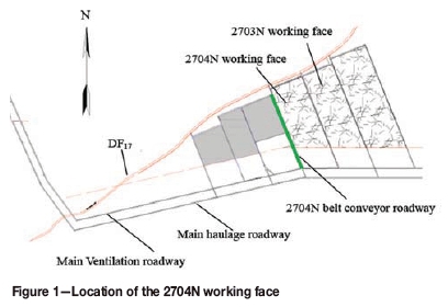
The 2704N mining face in the no. 2 panel of Xinyang mine, Shandong Xinwen Mining Group, China is located in the central to eastern section of the coalfield. The northeast region in the no. 2 panel, the western region of shaft station, and the adjacent east 2703N working face have been mined, whereas the no. 3 mining area in the west has not. The coal transport roadway begins at the seventh stratum in the no. 2 panel south of the DF17 (H = 0-32 m, angle 68°) stratum in the north. The burial depth of the coal seam is 464.7-517.4 m. The strike lengths range from 335 m to 359 m with an average of 347 m. The inclined length is 150 m. Coal seam dip angles range from 2° to 9° with an average value of 5°. Mining height is 1.2 m. The upper roof is 10.5 m thick and is composed of fine sandstone. The immediate floor is 2.6 m thick and is composed of siltstone. The hard floor is 5.5 m thick and is composed of medium sandstone. The shaft location of the 2704N working face is shown in Figure 1.
Numerical simulation
Establishment of the numerical method
The three-dimensional (3D) model of 2704N working face was established using the numerical simulation software FLAC3D. A total of 12.9 MPa vertical stress was applied at the upper boundary of the model to simulate stratum stress; the static earth pressure coefficient was unity; the lateral boundaries of the model restrict the horizontal displacement and the bottom boundary restricts the vertical displacement. The upper boundary is free. Paste filling materials were used for the roadside support body, and the width and height of the roadway cross-section after entry retention were 1.5 m and 1.2 m, respectively. The complete caving and gob-filling methods were adopted to simulate stress distribution in the rock surrounding the retained gob-side entry, with the condition that other parameters remained constant.
To further investigate the failure mechanism of the filling body along the gob and the effect of gob filling on the gob-side entry, a numerical simulation using particle flow code (PFC) was carried out.
Numerical calculation parameters
Field sampling and rock mechanics test results revealed that the rock mass underwent failure under maximum load strength. The residual strength of the rock mass gradually decreased with the development of deformation during a post-peak plastic flow process. Therefore, the Mohr-Coulomb yield criterion was used to calculate the failure of the rock mass (Equation [1]). The strain softening model was used to reflect the gradual degradation of the residual strength of the coal body after failure with the development of deformation (Huang et al, 2011).
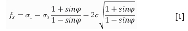
where fs is the shear failure index of the material, σ1 and σ3 are the maximum and minimum principal stresses, respectively, and c and φ are the cohesion force and frictional angle, respectively. When fs> 0, the material will undergo shear failure. As the tensile strength of the rock mass is very low, the likelihood of the rock mass undergoing tensile failure can be determined on the basis of the tensile strength criterion (σ3 ≥σT).
Gob caving materials feature macroscopic continuity and irreversible compressive deformation, and caving gangues exhibit permanent bulk shrinkage and strain hardening under isotropic pressure. This bulk hardening behaviour is described using the bulk hardening model (Figure 2).
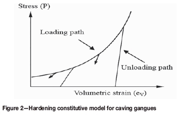
Gangue materials inside the gob are compacted as the working face advances during mining. Gangue caved from the gob presents a type of loose medium. The mechanical effect of gangue caving on the supporting root can be macroscopically approximated as a supporting body with irreversible deformation. Notably, with the advance of the working face and time, gangue is gradually compacted under the effect of overlying strata, and the material density, elasticity modulus, and Poisson's ratio increase over time.
Existing studies have shown that change rules can be expressed by Equations [2]-[4].
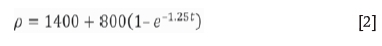
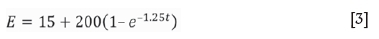
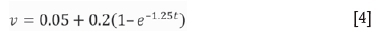
where ρ is material density (kg/m3), t is time (years), E is elasticity modulus (MPa), and υ is Poisson's ratio. Equations [2]-[4] reflect the changing relationships of p, E, and υ. These parameters exhibit exponential growth with time until finally becoming constant values.
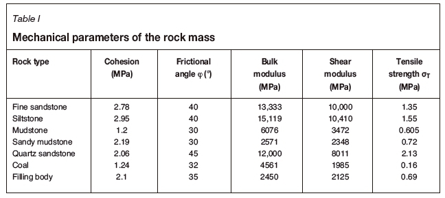
The main stratum parameters of the model are presented in Table I.
Field observation scheme
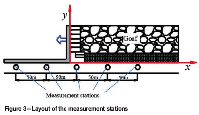
Three groups of anchor bolt stress measurement stations and roadway surface displacement measurement stations were arranged over the gob-side entry retention period of the 2704N working face. The interval between each measurement station was 50 m. Anchor bolt stress was monitored using an anchor bolt force meter installed at the tail of the anchor bolt. A KDW-1 multipoint displacement meter placed 50 m ahead of the anchor bolt force meter was used to monitor the surface displacement of the roadway. The layout of measurement stations is shown in Figure 3. To facilitate data processing, the coordinate value of the x-axis on the working face was defined as zero. The front of the working face was positive, whereas the rear was negative; for example, the coordinate value of axis x was -50 within 50 m inside the gob in the rear of the working face.
Results and discussion
Fracture criterion of the roadside filling body
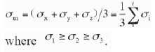
Coal seam mining disrupts the initial stress balance. Stress fields in the stope-surrounding rock gradually migrate, concentrate, and finally achieve a quasi-static balance to adapt to the mining environment. The stress state of any point in the stope-surrounding rock can be expressed as multiple forms, and a special circumstance among all descriptions, namely, three principal stresses σ/(ί= ι, 2, 3), arranged in vertical pairs, is found. The average stress is set as
The stress state of any point in the roadside filling body can be decomposed into the sum of the spherical and deviatoric stresses. The spherical tensor of stress only gives rise to the elastic change of the bulk roadside filling body, and the deviatoric tensor of stress results in the plastic deformation of the roadside filling body. The maximum principal deviatoric stress σί controls the degree of failure of the stope-surrounding rock, and its value can obtained through Equation [5] (Xu, Wei, and Xiao, 2015).
The coal seam floor is formed through specific geological processes and is subjected to a specific geological environment. The initial maximum principal deviatoric stress is zero; the mining process disrupts the initial ground stress balance and causes the maximum principal deviatoric stress field in the roadside filling body to change. The surrounding rock undergoes plastic failure when the maximum principal deviatoric stress σj exceeds the ultimate strength of the filling body.
Movement laws oflateral roofin the stope and rock beam structure
Plate theory (Xu et al., 2009) provides the macroscopic explanation for the fracture of the upper roof. When applying the caving method, the rock mass fails under maximum principal deviatoric stress, and the stope-surrounding rock expands from the shallow to the deep region toward the unsteady state, specifically manifesting during mining of the working face. The immediate roof caves, and the hanging upper roof stratum fractures when it reaches ultimate strength under the effects of overlying strata and self-weight. Fracture line I is first formed at two long edges during fracture. Subsequently, fracture line II appears at a short edge, the surrounding cracks thread in an 'O' shape, and the bending moment in the middle of the plate reaches the maximum value. Crack Ii is formed after the maximum strength of the rock mass is exceeded. Finally, an X-shaped failure forms, and the upper roof strata move and rotate along I and II, causing fracture line III to form structural blocks ί and 2 of the upper roof failure. The movement of the upper roof decreases as the upper beam of the rock roof first contacts the gangue in the middle of the gob. The plane figure of the upper roof after initial fracture presents as an ellipse and is called an 'O-X' fracture structure (Xu and Qian, 2000). The fracturing process of the rock stratum is shown in Figure 4.
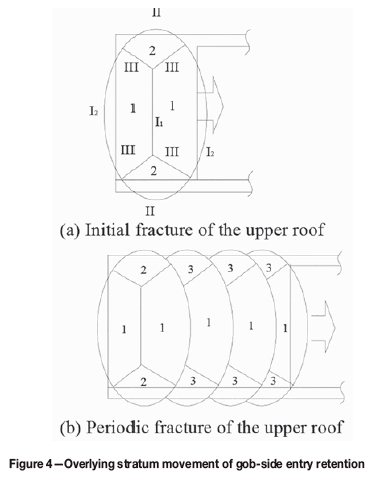
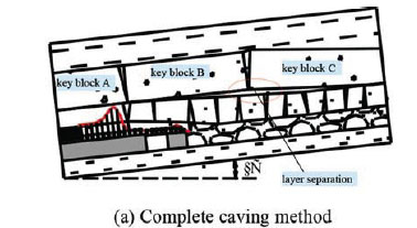
When the complete caving method is used to manage the roof after fracture, key strata mutually extrude to form a beam-like, semi-arched temporary structure with self-stabilizing balance. Three mutually occlusive key blocks - A, B, and C - form in the side direction of the gob, and the rock beam structure is formed after the fracture of key strata, as shown in Figure 4a. The retained gob-side entry is located underneath key block B, and the solid coal side and filling body side in the retained gob-side entry provide widely different mechanical environments. Specifically, key block B is unstable under the supporting effect of immediate roof caving and horizontal extrusion stresses of key blocks A and C. The compaction of the immediate roof and settling of key block C causes key block B to rotate and sink. The 'filling body-immediate roof-floor' jointly constitute the roadside support system, and the rotation and subsidence of key block B constitute the main stress sources in the system. Therefore, controlling the movement of key block B is the key for successful gob-side entry retention. The roadside support system cannot control the rotary deformation of key block B before the upper roof movement is completed, and the support system is mainly characterized by yielding.
The roadside filling body and gob filling body undergo compression during the rotation and subsidence of key block B. The final subsidence of key block B is given as:
where SEis the rotary subsidence of key block B, h is the mining height, mz is the thickness of the immediate roof, and KA is the expansion coefficient of the broken rock.
If backfilling is adopted, the effect of the gob filling body on the movement of the overlying strata is equivalent to the reduction of mining height and is replaced by the equivalent mining height. Equivalent mining height Meis expressed as Equation [7] in accordance with the features of the gob paste filling (Miao, Zhang, and Guo, 2010).
where h1 is the subsidence of the upper roof after the support is advanced (in mm); h2 is the restricted deformation quality of hydraulic support; h3 is the designed thickness of the upper beam of the hydraulic support (in mm); h4 is the upper roof subsidence during the paste filling process in the gob (in mm); h5 is the final settling volume of the immediate roof when the paste is compacted (in mm); h1 is the uncontrollable engineering quantity related to rock pressure; and h2-h5 are controllable engineering quantities related to the design of the hydraulic support and filling technology. Field mining height M is a fixed value. The effective feasible approach to decrease the equivalent mining height is to decrease h2-h5, namely, by decreasing the subsidence of the roof in the support area, timely filling, and shortening the setting time of the filling body.
One end of key block B is located inside the roadside coal body, whereas the other end rotates and subsides towards the gob. The 'coal body-roadside filling body-immediate roof support system fails to resist deformation and passively accepts this 'given deformation' state. The amount of deformation is given by Equation [8] (Zhang et al., 2012).
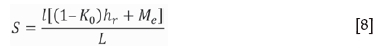
where l is the distance from a point in key block B to a fracture line at the roadside coal body, and K0 is the expansion coefficient of the caved rock strata. The expansion coefficient of broken hard sandstone is 1.3-1.35, whereas that of mudstone with relatively low strength is 1.25-1.28. The greater the K0 value, the smaller the given deformation of key block B; namely, the more the movement of key block B is restricted, the smaller the load borne by roadside filling body. In Equation [8], hr is the thickness of the immediate roof, and L is the length of key block B.
Equations [7] and [8] show that the effect of the gob paste filling is equivalent to a reduction in mining height. The subsidence space of the overlying strata is restricted and the immediate roof does not completely cave. The fracture structure shown in Figure 5a is not formed; however, it is in a broken-like state. The structure of the overlying strata after gob filling is shown in Figure 5b.
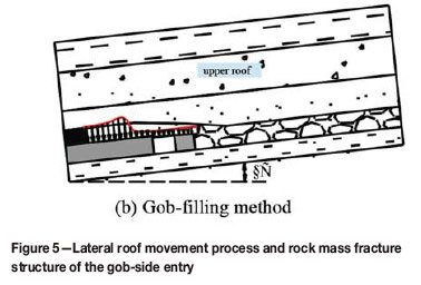
Dispersed particles are the basic components of the PFC. Material parameters include particle density, modulus of deformation of particles, normal/tangential stiffness ratio of particles, modulus of deformation of parallel bonds, coefficients of particle friction, and normal and tangential binding strength of parallel bonds. The parallel bond model was used as the mechanical constitutive model. The PFC simulation results demonstrated that the coal body in front of the working face, side coal body of the working face, filling body in the gob, immediate roof, and filling body along the roadway extrude mutually. Adjacent particle units form the bearing structure that supports the overlying rock movement through contact forces. Stress migrates and concentrates in the stope-surrounding rock during mining of the working face. Accompanied by the redistribution of rock strata stresses, a powerful force chain network is stored inside the skeleton structure (Figure 6). The force chain network includes strong force chains and weak force chains and exhibits extremely strong self-organizing and energy transfer capabilities. In Figure 6, weak force chains are represented by light gray lines, strong force chains are represented by black lines, and the intensity of force chains are expressed by line thickness. Strong force chains bear the majority of overlying stratum stress despite their low numbers in the gob-filling body. The minor disturbance of the overlying strata caused by the strong force chains in the gob-filling body is of a nonlinear response nature. Their bifurcation or instability would very easily cause the avalanche-like fracture of the key strata, resulting in the intense, large deformation of the roadside filling body. Therefore, the gob-filling body should be stable and effectively support the roof.
Mechanical environment ofroadside filling body and optimization ofregional stress
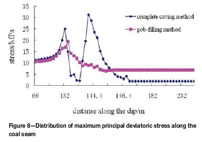
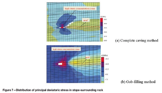
The distributions of the mechanical environment in the stope-surrounding rock in response to different mining methods are shown in Figure 7. Figure 7 was derived using FLAC3D numerical simulation software. Figure 8 shows the maximum principal deviatoric stress values of slant section 20 m at the rear part of the working face. The calculation results indicate that when the caving method is used, the fracture, rotation, subsidence, and contacting of gangue with the main roof induce a high-stress field to concentrate in the area of the roadside filling body. The maximum principal deviatoric stress borne by the roadside filling body is 34.5 MPa. After the gob is filled, the separation of stratum between the immediate and main roofs could be prevented to decrease the subsidence of the roof strata, exert a pressure 'yielding' effect on the roof strata, and prevent the accumulation of an excessively high principal deviatoric stress on the roadside filling body. The maximum principal deviatoric stress borne by the roadside filling body is approximately half of that when the complete caving method is used to manage the roof. Therefore, selecting the appropriate mining method is the most direct and effective method to ensure successful gob-side entry retention and adjust the uncontrollable remote stress of the roadside filling body.
Filling scheme and coal-gangue separation technology
Performance requirement for filling materials
The roadside filling body should have high deformability and a high load-bearing strength to seal the gob and support the roof while satisfying pumping requirements. Gob-filling behind hydraulic supports should sufficiently consume redundant gangue during underground mining and drifting processes while avoiding influencing regular production. Therefore, the mould for the gob-filling body behind the hydraulic supports should be removed after 3-4 hours to ensure that the working face can be mined as normal.
The optimal proportioning schemes of the roadside filling body and gob filling materials were selected through laboratory experiments and are presented below.
The composition of the roadside filling body is 42.5 ordinary Portland cement, river sand, gangue, and additive in proportions of 1, 3, 8, and 0.9 by weight, with compressive strengths at 3 hours, 1 day, 3 days, 7 days, and 28 days of 0.34, 11.3, 16.1, 19.9, and 29 MPa, respectively. When the mould is removed after 3 hours, the support body is filled and self-stabilized. The slump is greater than 160 mm. The pumping distance can reach 500 m.
Gob-filling materials should contain as much gangue as possible to decrease costs and realize a pumping distance of 500 m. Moreover, the filling materials should undergo self-compaction after being pumped to the mould. The weight ratio of the optimal proportioning scheme is water: gangue: coal ash: additive = 13.23: 79.23: 6.15 .
Shallow slot method for the underground separation of coal and gangue using heavy media
The shallow trough separator for heavy media is characterized by a small volume (5.5 x 3.9 m), strong adaptability to feeding stability, small loss caused by gangue mixing with coal (<0.5%), facile and convenient operation, and a high degree of automation. Therefore, the ground 'diamond-style' shallow trough for separation by heavy media was changed to a 'cavern long strip-style' separation unit after miniaturization and displacement by equipment to separate raw block coal in the 50-250 mm size range. The early separation of gangue from the panel was accomplished and on-specification raw coal and pure gangue were produced. The pure gangue was used for backfilling to realize green and environmentally friendly mining (Xu et al., 2009.
Case study A
Field research was conducted at 2704N working face in no. 2 panel of Xinyang coal mine to verify the effects of the new fully mechanized gob-side entry retention and gob filling technology behind hydraulic supports on stress adjustment and the structural control of gob-side entry retention area.
Design of filling system
Owing to the imbalance of underground production and many uncertain factors, if a large quantity of gangue was available and a surplus remained after filling for gob-side entry retention, the redundant materials were filled in the gob. The filling system for 2704N working face was designed as a parallel gob-side entry retention system and gob-filling system after support had been installed. Two sets of filling pumps were located inside the main roadway. The filling pumps did not move when the working face was mined. The mould base of the gob-side entry retention and hydraulic support of the filling template behind the hydraulic supports were arranged inside the working face and continuously formed new filling spaces as the workface was mined. The filling system was designed primarily to ensure gob-side entry retention. Gob filling was implemented only when the quantity of gangue was greater than was required for gob-side entry retention. Specifically, gob filling behind the hydraulic supports was done with the objective of consuming gangue (Qian, Miao, and Xu, 2007).
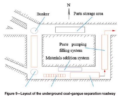
The existing coal bunker in the no. 2 panel and connecting roadway in the gangue bunker were transformed and the main separation system was arranged. The width and height of the connection roadway were increased to 6.8 m χ 7.0 m, and coal-gangue separation equipment was arranged in the connecting roadway. To facilitate installation and overhaul of the clean coal and coarse slime screen, a pressure filter was installed inside the sealed and unused coal transportation roadway in the 2701N working face, and crushed gangue was stored in the roadway. Qualified and diluted medium pools were arranged inside the connecting roadway for subsidence treatment and automatically flowing qualified media were collected. The installation and maintenance requirements for the separation equipment were fully considered so as not to interfere with the gangue crushing system, thus ensuring the smooth implementation of the filling work. The layout of the underground coal-gangue separation roadway is shown in Figure 9.
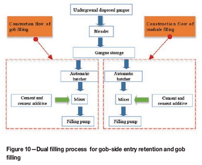
The material preparation system was set up in accordance with the dual system design. Crushed gangue was used to fill the retained gob-side entry through a set of mixed material proportioning, blending, and pumping systems. Gob filling behind the hydraulic supports was implemented through another set of mixed material proportioning, blending, and pumping systems. The flow chart of this dual filling system is shown in Figure 10.
Filling technology
Filling technology for gob-side entry retention
Filling beside the roadway was implemented once for every three slices of coal cut. Coal mining and roadside mining could be conducted simultaneously, and a filling body with dimensions of 1.8 m (length) x 1.3 m (height) x 2.5 m (width) (5.85 m3) was formed behind the hydraulic supports once filling was implemented. To facilitate removal of the template, plastic film was laid on the template support and surface before filling. During roadway filling, a metal or plastic net, originally used to protect the coal body inside the coal transportation roadway in the working face, was cut off and used to reinforce the filling body.
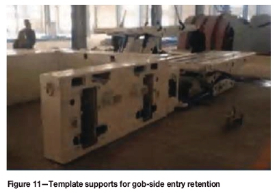
Template supports (Figure 11) used for gob-side entry retention in the working face were all in lagging support forms. The support was advanced after the scraper conveyor when the coal body was cut by a coal cutter. Filling was started only when the template supports had advanced for three cycles, and filling and coal cutting could be implemented simultaneously. Filling work could be completed after the cutting of the third cycle was completed.
Gob-filling technology after support
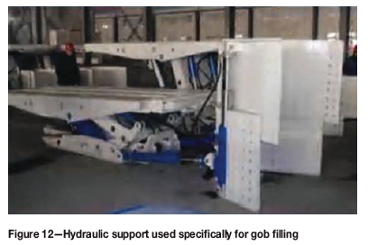
The cutting depth of the coal cutter in the 2704N working face was 0.6 m. Template supports (Figure 12) could be filled forward after two slices of coal were cut from the working face and the scraper conveyer was moved. This would not influence the cutting of the third slice of coal. A 1.8 m x 1.2 m χ 1.5 m (3.51 m3) filling space was formed after the template supports were removed, and the 3.51 m3 space was used for concrete filling each time. The construction processes proceeded simultaneously, and the gob was filled once the templates were moved. To ensure the appropriate moisture content of filling materials during freezing and for the convenience of moving the filling templates, plastic films were laid down on the template supports and template surfaces before filling.
Support reinforcement scheme for gob-side entry retention
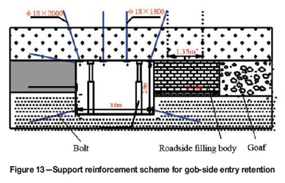
Roof support was reinforced in the gob-side entry retention area during the mining of the 2704N working face. The spacing between anchor bolts was 1.35 m, and the row spacing was 1.0 m. The filling method was used to form a concrete wall at the rear of the support after anchor bolts were installed to maintain the roadway, and the width of filling body was 2.5 m. Three rows of single hydraulic props were used for support reinforcement within 50 m of the front of the working face, and two rows of single hydraulic props were set within 200 m influence range of dynamic pressure at the rear of the working face. The amount of deformation of the surrounding rock in the retained gob-side entry was controlled within the permitted range, and props were removed after the movement of the stratum overlying the mined working face stabilized. The original three-support temporary support on the end of working face was replaced by the mould base of the gob-side entry retention. The support reinforcement mode for gob-side entry retention is shown in Figure 13.
Field measurement of the entry retention effect
Figure 14 shows the results of anchor bolt stress tests for roof management in the retained gob-side entry. The results revealed considerable changes in stress, with a peak stress of 11.5 MPa within the distance of 50 m from the measurement station to the coal mining face. When the distance from the face was 60 m, the immediate roof was forced to subside because of the rotation of the key blocks. Support inside the roadway did not change the movement mode of the large structure in the surrounding rock. The anchor bolt stress increased slightly after entering the gob, reaching a maximum value of 4.8 MPa at approximately 40 m from the rear of the working face. As the movement of the surrounding rock tended to be stable, the anchor bolt stress tended to be mild. The rotary subsidence of the roof after gob filling was restricted, thus preventing separation of the overlying strata and the development of fractures. The anchor bolt stress decreased significantly to a peak value of 7.7 MPa. Field observation revealed that the high stress generated by the movement of the surrounding rock was not controlled solely through the roadside support and the basic support inside the roadway, since the deformation space permitted by gob-side entry retention in thin coal seams was limited. Gob filling enhanced control of the roof strata and had a beneficial effect on regulating high stress on the roadside filling body.
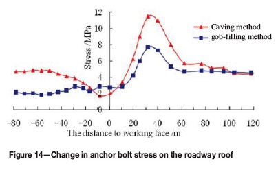
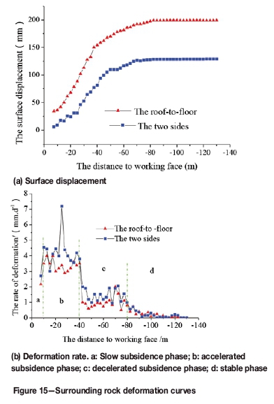
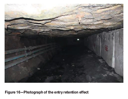
Figure 15 shows the deformation of the rocks surrounding the gob filling in the retained gob-side entry. The mechanical environment of the roadside support body was improved because the gangue filling inside the gob bore the majority of the pressure from the overlying strata. Thus, the maximum cumulative displacement of the roof and floor was only 203 mm. Since the mining face was exploited until the roadside filling body lagged the mining face by 87 m, displacement between the roadway roof and floor gradually increased. This indicated that the overlying stratum moved within this range. In the meantime, the horizontal stress concomitant with the vertical deformation of the filling body inside the gob was transferred to the roadside filling body. The phenomena in the surrounding rock of the retained gob-side entry could be divided into a slow subsidence phase (Οίο m behind the working face), accelerated subsidence phase (16-42 m behind the working face), decelerated subsidence phase (42-85 m behind the working face), and stable phase (87 m behind the working face). These phases are influenced by the rapid, slow, and constant increases of the filling body intensity in the gob area. The roof underwent subsidence mainly by bending, whereas the floor underwent base swelling. The entry retention section was maintained above 89% of the original section, thus meeting the use requirement for the next working face. The actual effect of gob-side entry retention is shown in Figure 16.
Conclusion
This study aimed to characterize the failure mechanism of the roadside filling body and to achieve gob-side entry retention in thin coal seams. Thus, the distribution laws of deviatoric stresses of the roadside filling body under two roof management conditions - caving method and gob filling -were described on the basis of elastic-plastic mechanics and mining pressure theory, stress adjustment, and structural control theory in the gob-side entry retention area. A new proactive roof-support technology that combines fully mechanized gob-side entry retention in thin coal seams and gob filling at the rear of hydraulic supports was designed. The following conclusions can be drawn.
► Different mining methods result in different distributions of mechanical environments in stope-surrounding rocks. Decreasing the uncontrollable high stress borne by the roadside filling body is the most direct and effective method of controlling the accumulation of excessive principal deviatoric stress on the roadside filling body.
► Filling gobs with gangue has an effect equivalent to decreasing the mining height, since it restricts the available space for subsidence of the overlying strata. The strong force chains in the gob-filling body bore the majority of the stresses from the overlying strata. Key blocks were in a near-broken state under high extrusion stresses at the two sides, and the stability of the rock mass surrounding the retained entry was significantly improved.
► A novel technology that combines proactive roof support with fully mechanized gob-side entry retention is proposed for application in thin coal seams, with gob filling behind hydraulic supports. A mutually independent rapid filling technology was designed to improve the mechanical environment of the roadside support body, significantly decrease displacement of the roof and floor, and satisfy the cross-section requirement of retained entry ventilation for the next working face.
In conclusion, this study proposes a clear and simple mechanism for the plastic deformation of a roadside filling body under deviatoric stresses. This mechanism is proposed on the basis of stress adjustment and structural control theory and technology. However, only increments in anchor bolt stress, anchor rope stress, and roadside vertical stress, as well as deformation in the rock surrounding the gob-side entry retention, were monitored owing to the lack of instruments for monitoring 3D stress fields in real time. 3D stress meters are required for the characterization of the dynamic evolution of deviatoric stress in a filling body along a retained gob-side entry during coal mining. The development of such instruments will contribute significantly to characterization of the stability of a filling body along a retained gob-side entry and enable the proactive regulation of high stress.
Acknowledgments
This research was supported by the National Key Research and Development Program of China (2017YFC0804202), the State Key Program of National Natural Science Foundation of China (U1361208), the National Natural Science Foundation of China (51504005, 51304007), and Anhui Provincial Natural Science Foundation (1408085MKL42).
References
Bai, J.B., Zhou, H.Q., Hou, C.J., and Yue, D.Z. 2004. Development of support technology beside roadway in goaf-side entry retaining for next sublevel. Journal of China University of Mining and Technology, vol. 33, no. 2. pp. 59-62. [ Links ]
Chen, S. 1994. Calculation of additional stresses in soil produced by infinite long ladder-shaped distribution load. Suzhou Institute of Urban Construction and Environmental Protection, vol. 7, no. 3. pp. 29-32. [ Links ]
Golshani, A., Oda, M., Okui, Y., Takemura, T., and Munkhtogoo E. 2007. Numerical simulation of the excavation damaged zone around an opening in brittle rock. International Journal of Rock Mechanics and Mining Sciences, vol. 66, no. 4. pp. 835-845. [ Links ]
Huang, Y.L., Zhang, J.X., Zhang, Q., and Zanm D.F. 2011.Technology of gob-side entry retaining on its original position in fully mechanized coalface with solid material backfilling. Journal of China Coal Society, vol. 36, no. 10. pp. 1624-1628. [ Links ]
Li, L.C., Yang, T.H., and Liang, Z.Z. 2011. Numerical investigation of ground water outbursts near faults in underground coalmines. International Journal of Coal Geology, vol. 85, no. 3. pp. 276-288 [ Links ]
Ma, L.Q., Zhang, D.S., Chen, T., and Fan G. 2007. Study on packing body supporting resistance of enter-in packing for in situ gob-side entry retaining in fully-mechanized top-coal caving mining face. Chinese Journal of Rock Mechanics and Engineering, vol. 26, no. 3. pp. 544-550. [ Links ]
Mark, C., Gale, W., Oyler, D., and Chen, J. 2007. Case history of the response of a longwall entry subjected to concentrated horizontal stress. International Journal of Rock Mechanics and Mining Sciences, vol. 44, no. 2. pp. 210-221. [ Links ]
Miao, X.X., Zhang, J.X., and Guo, G.L. 2010.Study on waste-filling method and technology in fully-mechanized coal mining. Journal of China Coal Society, vol. 35, no. 1. pp.1-6. [ Links ]
Mohammad, N., Reddish, D., and Stace, L. 1997.The relation between in situ and laboratory rock properties used in numerical modeling. International Journal of Rock Mechanics and Mining Sciences, vol. 34, no. 2. pp. 289-297. [ Links ]
Qian, M.G., Miao, X.X., and Xu, J.L. 2007. Green mining of coal resources harmonizing with environment. Journal of China Coal Society, vol. 32. pp. 1-7. [ Links ]
Schumacher, F.P. and Kim, E. 2014. Evaluation of directional drilling implication of double layered pipe umbrella system for the coal mine roof support with composite material and beam element methods using FLAC3D. Journal of Mining and Safety Engineering, vol. 55, no. 2. pp. 335-348. [ Links ]
Shabanimashcoo, L.M. and Li, C.C. 2013.A numerical study of stress changes in barrier pillars and a border area in a longwall coal mine. International Journal of Coal Geology, vol. 106. pp. 39-47. [ Links ]
Smart B.G.D. and Haley S.M. 1987. Further development of the roof strata tilt concept for pack design and the estimation of stress development in a caved waste. Mining Science and Technology, vol. 5, no. 2. pp. 121-130. [ Links ]
Xie, H.P., Zhang, Z.T., and Gao F. 2016. Stress-fracture-seepage field behavior of coal under different mining layouts. Journal of China Coal Society, vol. 41, no. 10. pp. 2405-2417. [ Links ]
Xu, J.L. and Qian, M.G. 2000. Method to distinguish key strata in overburden strata. Journal of China University of Mining and Technology, vol. 29, no. 5. pp. 463-467. [ Links ]
Xu, J.L., Wang, X.Z., Liu, W.T., and Wang, Z.Q. 2009. Effects of primary key stratum location on height of water flowing fracture zone. Chinese.Journal of Rock Mechanics and Engineering, vol. 28, no. 2. pp. 380-385. [ Links ]
Xu, L., Wei, H.X., and Xiao, Z.Y. 2015. Engineering cases and characteristics of deviatoric stress under coal pillar in regional floor. Rock and Soil Mechanics, vol. 36, no. 2. pp. 561-568. [ Links ]
Zhang, D.S., Mao, X.B., and Ma, W.D. 2002.Testing study on deformation features of surrounding rocks of gob-side entry retaining in fully-mechanized coal face with top-coal caving. Chinese Journal of Rock Mechanics and Engineering, vol. 21, no. 3. pp. 331-334. [ Links ]
Zhang, J.X., Jiang, H.Q., Miao X.X., Zhou, N., and Zan, D.F. 2013.The rational width of the support body of gob-side entry in fully mechanized backfill mining. Journal of Mining and Safety Engineering, vol. 30, no. 2. pp. 159-164. [ Links ]
Zhang, N., Chen, H., and Chen, Y. 2015. An engineering case of gob-side entry retaining in one kilometer-depth soft rock roadway with high ground pressure. Journal of China Coal Society, vol. 40, no. 3. pp. 494-501. [ Links ]
Zhang, Q., Zhang, J.X., Huang, Y., and Feng, J. 2012. Backfilling technology and strata behaviors in fully mechanized coal mining working face. International Journal of Mining Science and Technology, vol. 22, no. 2. pp. 151-157. [ Links ]
Paper received Jan. 2017
Revised paper received Oct. 2017

