


Services on Demand
Article
 English (pdf)
 Article in xml format
 Article references
Indicators

Related links
-
 Cited by Google
 -
 Similars in Google
Share

 Permalink
Journal of the Southern African Institute of Mining and Metallurgy
On-line version ISSN 2411-9717
Print version ISSN 2225-6253
J. S. Afr. Inst. Min. Metall. vol.118 n.5 Johannesburg May. 2018
http://dx.doi.org/10.17159/2411-9717/2018/v118n5a3
PAPERS OF GENERAL INTEREST
Numerical analysis and case study on the mitigation of mining damage to the floor of no. 5 coal seam of Taiyuan Group by grouting
A. LiI; Y. LiuII; L. MouI; K. LiIII
ISchool of Architecture and Civil Engineering, Xi'an University of Science and Technology, China
IIHydrogeological Research Institute, China Coal Technology & Engineering Group, China
IIIDepartment of Mining Engineering, West Virginia University, USA
SYNOPSIS
Based on the geological condition of panel 22507 of the no. 5 coal seam at Dongjiahe coal mine, numerical analysis of the stability and water permeability of the floor aquiclude before and after grouting was conducted using Rock Failure Process Analysis (F-RFPA2D). The dynamic development, extension, and distribution of the cracks in the aquiclude are discussed. It is shown that grouting can increase the effective thickness of the aquiclude, reduce the floor damage depth, and control the floor water inrush path, thus effectively improving the overall strength and water blocking capability of the aquiclude. These numerical study results were applied to facilitate relevant engineering work at Dongjiahe coal mine. The mitigation measures involved grouting the floor of the no. 5 coal seam, allowing panel 22507 to be mined safely above confined water. This exercise provided invaluable experience in preventing water inrush hazards.
Keywords: grouting, aquiclude, aquifer, numerical analysis, field practice.
Introduction
As the mining depth in the Chenghe mining area of the Weibei coalfield has increased, the coal seam floor has been subject to increasing pressure from the Ordovician limestone overburden, which in turn has increased the potential hazard of water inrush (Li, Gu, and Chen, 2013; Wang and Park, 2003; Wei et al., 2010; Wu, Jiang, and Zhai, 2011; Zhang and Shen, 2004; Zhang, 2005). The Dong'iahe coal mine is one of the major mines in the Chenghe mining area (Li et al., 2015). Following decades of mining, the upper seams are almost mined out and most of the mining activities have moved to the lower no. 5 coal seam. The no. 5 seam is located above the Ordovician limestone and K2 aquifers of the Taiyuan Group, with the former posing the main threat to mining safety. The distance between the no. 5 seam and the Ordovician limestone aquifer is about 25-35 m, leading to a very high possibility of water inrush hazard. Currently, considerations of cost, environmental impact, and feasibility dictate that mining under high water pressure is the main method used to extract the coal resources above confined water (Li et al., 2015; Lu et al., 2015). However, the water inrush risk associated with this method is high (Feng and Jiang, 2015; Li and Wang, 2003), making it very important to protect the coal seam floor effectively (Guan, Li, and Lu, 2003; Liu, 2008; Yang et al., 2007). Much fruitful research has been conducted on the mechanism of floor water inrush (Duan, 2014; Jiang, 2011; Liu and Hu, 2007; Liu et al., 2013; Wang et al., 2004; Wang 2012). However, very little has been done to better understand how to protect coal seam floors, although a few studies have assessed issues such as floor damage during mining, stress distribution, and seepage before and after coal seam floor mitigation (Chen, Xie, and Jing, 2006; Lu and Wang, 2015; Yuan, Li, and Jiao, 2015).
In this study, the lithology of the floor strata of the no. 5 coal seam in Dong'iahe coal mine was used as a basis for a systematic assessment of coal seam floor damage under high water pressure before and after floor mitigation. The Rock Failure Process Stress-Seepage Coupling Analysis software (F-RFPA2D) was used to model coal seam floor damage in detail under the coupling of seepage and stress fields. The dynamic process of initiation, development, connection, and forming of water-conducting paths was analysed. The numerical modelling results were used to design and plan a floor grouting field test on the K2 aquifer. This theoretical analysis and field floor grouting test provide significant insight into water inrush prediction, mining method optimization, and safety evaluation for both the no. 5 seam and the Chenghe mining area as a whole.
Hydrogeological conditions
Panel 22507 of the no. 5 coal seam in Dong'iahe coal mine was selected for field testing. The panel is located at the east side of the downhill belt entry of the second mining area, with solid coal to the north and a 30 m barrier pillar to the south. The average thickness of the coal seam is 3.6 m and the elevation of the panel is around +255 to +273 m. The length of the panel in the strike direction is 910 m and the width in the dip direction is 114 m. The panel is mined using longwall extraction with roof caving. The average inclination of the coal seam is 3°. The no. 5 coal seam is located in the upper section of the Taiyuan Group. The immediate roof is hard grey K4 medium sandstone with a thickness of 10.918.15 m. The immediate floor is dark grey coarse siltstone with a thickness of 0.2-3.21 m, while the main floor is fine K3 quartz sandstone or siltstone with a thickness of 3.47.8 m. Based on documented data, the panel is in a very complicated hydrogeological condition and is mined above confined water. The distance between the bottom of the coal seam and the top of the Ordovician limestone is about 28 m, which poses a high potential for water inrush.
The hydrogeological data shows that the roof of panel 22507 is composed of medium-grained and other types of sandstone, while the floor of the no. 5 coal seam is composed of medium-grained sandstone, mudstone, and thin limestone. This section of the strata has medium consolidation, good compactness, and very few cracks, indicating a high-quality aquiclude that blocks water inrush from the Ordovician limestone. However, there is a weak to medium karst fracture aquifer between the no. 5 seam and the Ordovician limestone aquifer. This aquifer is composed of Upper Carboniferous Taiyuan Group quartz sandstone and K2 limestone, with a high water content at high pressures. These characteristics and the short distance between the aquifer and the no. 5 seam constitute a significant threat to the mining of the seam.
Numerical simulations
Rock Failure Process Stress-Seepage Coupling Analysis software (F-RFPA2D) was employed to study the mitigation of K2 aquifers using floor grouting. Based on this stressseepage coupling analysis, the dynamic process of fracture initiation, development, connection, and formation of water-conducting paths at the floor aquiclude of panel 22507 was simulated and analysed.
Numerical model
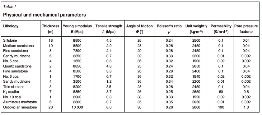
The physical and mechanical parameters used in the numerical simulation were derived from the roof and floor strata lithologies of panel 22507 and are listed in Table I. Figure 1 shows the mechanical model of the panel, with mining occurring above the confined water level, used for numerical simulation. The model is 230 m in length and 100 m in height, with 230 χ 100 (total 23 000) elements. From top to bottom, the strata in the model are main strata, main roof, immediate roof, coal seam (4 m), upper aquifer (14 m), K2 aquifer (7 m), lower aquiclude, and Ordovician limestone aquifer. The aquiclude at the top of the Ordovician limestone aquifer comprises the no. 10 coal seam and aluminous mudstone. The water head at the Ordovician limestone aquifer is 140 m.
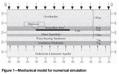
The bottom of the model was fixed in the vertical direction and the two corner points at the bottom and side were fixed in both the vertical and horizontal directions. The two sides were fixed in the horizontal direction. The top and bottom of the model consisted of water-confining boundaries. The overburden depth was 350 m, which was loaded on top of the model as a distributed stress (Q) of 6.6 MPa based on an average overburden strata density of 2150 kg/m3. The numerical simulation was conducted in a stepwise manner: in the first step, the self-weight of the strata was balanced; in the following steps, mining commenced 65 m from the left boundary. The mining distance for each step was 8 m, with a total mining distance of 96 m over 13 mining steps.
Numerical simulation analysis without grouting
The first numerical model iteration simulated the mining process without grouting of the floor. The development and distribution of floor fractures, abutment pressure, and floor seepage characteristics are discussed in the following sections.
Floor fracture development and distribution
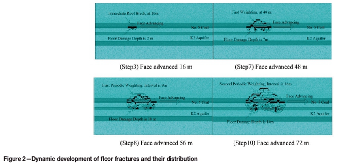
Figure 2 shows the dynamic development and extension of the floor fractures and their distribution in the floor aquiclude of the no. 5 seam. Four steps with face advances of 16, 48, 56, and 72 m were selected for demonstration.
As the coal seam is mined, the roof and floor strata begin to break. When the face advances to 16 m, the immediate mudstone roof over the gob area breaks for the first time, with a roof break height of 6 m. Some tensile shear failure zones develop in the floor under the gob area, with a damage depth of about 2 m. The floor demonstrates good water-blocking capability. Slight floor heave of about 46.2 mm occurs in the centre of the gob area, as shown in Figure 2 (step 3).
When the face advances to 48 m, the fractures in the roof rock beam propagate upward continuously and the first weighting occurs on the main roof. The roof caving height is about 11 m. The floor tensile shear failure zone extends deeper, inducing serious damage to the main floor extending to 7 m depth The floor heave increases to about 53.2 mm, as shown in Figure 2 (step 7).
When the face advances to 56 m, the fractures in the roof strata continuously propagate to the medium sandstone layer. The first periodic weighting occurs on the main roof. The voids under the gob area increase and the fractures on the floor continuously extend to the low-strength sandy mudstone layer owing to tensile and compressive shear action. The overlying hard rock strata all fail and lose their water-blocking characteristics. At this point, the floor damage reaches 10 m depth. Erosion by water in the K2 aquifer leads to the creation of a 1 m thick progressive fracture zone about 2 m away from the floor damage zone, which stops the development of fractures. The maximum floor heave is about 85.6 mm, as shown in Figure 2 (step 8).
When the face advances to 72 m, periodic weighting continues on the main roof. However, owing to the strong sandstone layer in the overburden, the roof fracture does not propagate to the surface. The floor aquiclude is now in a state of unloading, and the floor tensile shearing failure continues to develop under the combined effects of mining abutment pressure and seepage fields. The fractures finally penetrate the fine sandstone layer above the aquifer and connect to the progressive fracture zone in the K2 aquifer, forming a water-conducting path. Water confined within the aquifer seeps through the fractures in the floor aquiclude and enters the gob area, resulting in a floor water inrush. The floor bending heave increases rapidly to a maximum of 433.8 mm, as shown in Figure 2 (step 10).
Abutment pressure distribution
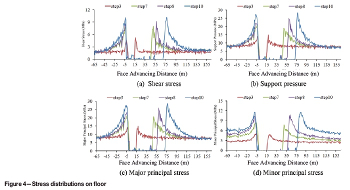
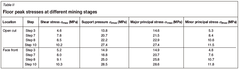
Figure 3 shows the shear stress distribution on the floor of the seam. The various degrees of brightness represent changes in the magnitude of the shear stress. Figure 4 and Table II show the floor strata shear stress, support pressure, major and minor principal stresses, and peak stresses at the open cut and face front areas as the longwall face advances.
As the face advances, stress redistribution around the mining area induces symmetrically distributed shear stress on the sidewall of the gob, as shown in Figure 3 (step 3). Stress concentration occurs at the open cut and face front areas. When the face advances to 16 m, first weighting occurs on the immediate roof. At this moment, the floor peak shear stresses are 4.6 and 5.2 MPa at the open cut and face front areas respectively, the corresponding support peak stresses are 13.8 and 14.9 MPa, the major principal stress peaks are 14.6 and 14.9 MPa, and the minor principal stress peaks are 5.2 and 4.8 MPa, as shown in Figure 4 and Table II.
The shear failure area on the gob sidewalls increases as the face advances, with the shear stress symmetrically distributed as shown in Figure 3 (step 7). When the face advances to 48 m, the stress concentration increases at both the open cut and face front areas, inducing the first weighting of the main roof. The damage zone in the floor under the gob extends downward and the area of tensile shear failure increases. At this point, the floor peak shear stresses are 7.8 and 8.0 MPa at the open cut and face front areas, respectively, the corresponding support peak stresses are 20.7 and 18.8 MPa, the major principal stress peaks are 21.5 and 20.7 MPa, and the minor principal stress peaks are 8.4 and 7.6 MPa.
As the face advances, the floor shear failure area under gob increases from the combined effects of abutment pressure and water pressure. The stress concentrations at the open cut and face front areas both increase. When the face advances to 56 m, a 1 m-thick progressive fracture zone forms in the fine sandstone layer at the top of the K2 aquifer. At this point, the floor peak shear stresses are 8.5 and 9.1 MPa at the open cut and face front areas, respectively, the corresponding support peak stresses are 22.2 and 25.0 MPa, the major principal stress peaks are 22.9 and 25.8 MPa, and the minor principal stress peaks are 10.6 and 10.7 MPa.
When the face advances to 72 m, the floor deformation increases rapidly owing to the combined effect of mine abutment pressure and seepage. There is a large tensile shear failure area in the floor aquiclude and the damage depth exceeds 13 m. The mining-induced floor fractures connect with the progressive fracture zone in the sandstone layer and form a water-conducting path. As shown in Figure 3 and Table II, the stress concentrations at the open cut and face front areas are fairly high. At this point, the floor peak shear stresses are 10.2 and 10.3 MPa at the open cut and face front areas, respectively, the corresponding support peak stresses are 27.4 and 28.5 MPa, the major principal stress peaks are 27.4 and 28.6 MPa, and the minor principal stress peaks are 11.5 and 11.8 MPa
Floor seepage analysis
Figure 5 shows the floor water flow rate vector distribution for the seam and the floor vertical flow volume curves under the gob area. Table III shows the maximum floor flow rate at each mining step.
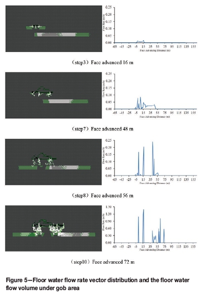
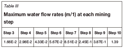
As the face advances, the water flow rate and volume increase under the gob area. When the face advances to 16 m, the floor water flow rate is relatively small - only about 1.66 χ 10-2 m/h - and the floor water inrush is mainly from the fracture water in the mining fracture zone of the immediate floor. The water flows through the open cut area and the mining face into the gob area. At this point, a sandy mudstone layer still exists between the floor fracture zone and the K2 aquifer, despite the aquifer's water pressure, and the top of the aquifer does not connect to the floor fracture zone. (Figure 5, step 3)
When the face advances to 48 m, the floor water flow rate increases to 8.51 χ 10-2 m/h and the water inrush is mainly from the fractures in the quartz sandstone and fine sandstone layers in the immediate floor. The water outlet locations are mostly in the gob area. The effective aquiclude above the K2 aquifer still has very good water-blocking capability.
When the face advances to 56 m, the floor tensile shear failure range of the aquiclude increases under the combined effect of abutment pressure and high water pressure. This damage propagates to the sandy mudstone layer above the K2 aquifer, with a damage depth of about 10 m, and the water flow rate increases to 2.45 χ 10-1 m/h, as shown in Table III. The water outlet locations are mostly in the centre of the gob area, the open cut area, and the mining face area. Owing to the effects of erosion due to the high pressure water, a 1 m forward fracture zone occurs in the K2 aquifer. The floor fracture zone still does not connect to the K2 aquifer and no water-conducting path forms.
When the face advances to 72 m, the floor damage depth extends downward and the effective thickness of the floor aquiclude decreases. The high-pressure water in the K2 aquifer breaks the sandstone layer and the floor fracture zone and connects to the gob area, forming a water-conducting path. The floor water flow volume increases rapidly and the floor water flow rate increases to 1.39 m/h, which is three times the flow rate before the water inrush. Finally, the combined effects of the abutment pressure and seepage field causes the high-pressure water in the aquifer to flow into the gob area through the conducting path in the floor aquiclude, resulting in a water inrush.
Discussion
Based on the above numerical simulation results, the following observations can be made.
Taking the floor strata lithology into consideration, the floor strata between the no. 5 coal seam and the Ordovician limestone aquifer are essentially composed of soft and hard rock layers, a strata composition that has good water blocking qualities. The top of the floor aquiclude comprises a high-strength, hard rock layer, while the top of the Ordovician limestone aquifer comprises a thick aluminous mudstone with a high water-blocking capacity. However, the middle of the floor aquiclude consists of the K2 aquifer composed of quartz sandstone and K2 limestone, with highly developed fractures. The presence of this K2 aquifer reduces the stability and the water-blocking capability of the floor aquiclude.
Based on the numerical simulation results, the influence of mining activity on floor deformation will be very small in the initial stage of mining, even with a confined aquifer within the floor aquiclude. As the mining face advances, the floor damage depth will be extended as the aquiclude above the aquifer is impacted by confined water seepage. Finally, when the progressive fracture zone connects with the floor damage zone, a water-conducting path is formed. The water in the sandstone layer will rush into the gob area through the water-conducting path with an inrush volume proportional to the water pressure of the aquifer.
Compared to the high-pressure and high-volume water in the underlying Ordovician limestone aquifer, the water inrush from the K2 aquifer is relatively small. If the floor damage zone is not connected to the Ordovician aquifer, the water inrush from the K2 aquifer will not cause serious problems. However, if a potential water-conducting path exists between the quartz sandstone or K2 limestone layer and the Ordovician limestone aquifer, the water in the latter will refill the aquifer and flow to the mining face, resulting in a hazardous water inrush accident.
Numerical simulation analysis with floor grouting
Numerical analysis was conducted to determine the effects of mitigation of the coal seam floor on the K2 aquifer. Mitigation measures to improve the total strength and water-blocking characteristics of the floor's effective aquiclude were assessed. The simulation used the numerical model shown in Figure 1. The rock mechanics parameters were identical for each stratum, save for the strength, permeability, and pore pressure of the 7 m thick K2 aquifer. Table IV shows a comparison of the rock mechanics parameters before and after mitigation.
The numerical simulation was conducted in a stepwise manner: first, the self-weight of the strata was balanced, and then mining commenced at 65 m from the left boundary in 14 steps of 8 m out to a total mining distance of 104 m.
Floor fracture development and distribution
Figure 6 shows the dynamic development and extension of the floor fractures and their distribution on the floor aquiclude of the no. 5 coal seam after K2 aquifer grouting mitigation. Four steps with face advance distances of 40, 56, 88, and 96 m are selected for demonstration.
As the coal seam is mined, stress concentrations occur at the open cut and mining face areas, and the roof and floor strata start to break. When the face advances to 40 m, the main roof of fine sandstone over the gob area undergoes first weighting, and the roof break height is about 11 m. The floor under the gob area develops some tensile shear failure zones and the damage depth is about 5 m. A slight floor heave of only 18.7 mm occurs in the center of the gob area, as shown in Figure 5 (step 6).
When the face advances to 56 m, the first periodic weighting occurs on the main roof and the fractures in the roof rock beam propagate upward continuously to a depth of about 14 m. The floor tensile shear failure zone extends deeper, inducing serious damage to the main floor, and the floor damage depth reaches 7 m. The floor heave increases to about 27 mm, as shown in Figure 5 (step 8).
When the face advances to 88 m, the main roof has already undergone three periodic weightings and the fractures in the roof strata continuously propagate to the medium sandstone layer. The voids under the gob area increase and the fractures in the floor continuously extend to the low-strength sandy mudstone layer owing to tensile and compressive shear action. The hard rock strata above have all failed and have lost their water-blocking characteristics. At this point, the floor damage depth reaches 11 m. The maximum floor heave is about 85.6 mm, as shown in Figure 5 (step 12).
When the face advances to 96 m, periodic weighting occurs again on the main roof. The roof fracture propagates to the surface owing to breakage of the strong sandstone layer in the overburden. The floor tensile shear fractures cease to propagate downward, and the floor damage depth reaches its maximum value of 11 m. The floor bending heave is compacted with caved roof rocks, and the floor heave reduces to 63.5 mm, as shown in Figure 5 (step 13).
Abutment pressure distribution
Figure 7 shows the floor strata shear stress, support pressure, and major and minor principal stresses after K2 aquifer grouting.
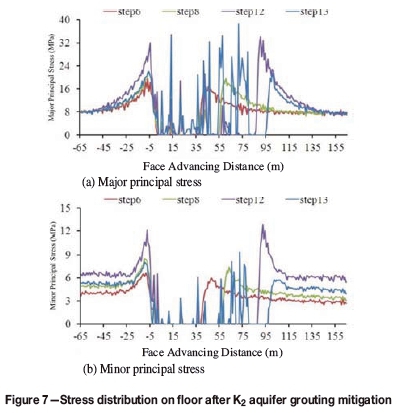
The advance of the mining face induces stress redistribution around the mining area. When the face advances to 40 m, first weighting occurs on the immediate roof. At this point, the peak floor shear stress, support pressure, and major and minor principal stresses are 6, 19.5, 19.6, and 6.5 MPa, respectively, at the open cut area. The peak floor shear stress, support pressure, and major and minor principal stresses at the face front area are 5.1, 16.6, 17.0, and 5.8 MPa, respectively.
When the face advances to 56 m, the stress concentration at the open cut and face front areas increases and induces the first periodic weighting of the immediate roof. At this point, the peak floor shear stress, support pressure, and major and minor principal stresses are 9.4, 21.6, 21.6, and 8.4 MPa, respectively, at the open cut area. The peak floor shear stress, support pressure, and major and minor principal stresses at the face front area are 8.8, 19.2, 19.5, and 7.4 MPa, respectively.
As the face advances further, the stress concentration at the open cut and face front areas continues to expand and increase. When the face advances to 88 m, the immediate roof above the gob area has already undergone three periodic weightings. At this point, the peak floor shear stress, support pressure, major principal stress, and minor principal stress are 11.2, 31.3, 31.9, and 12.2 MPa, respectively, at the open cut area. The peak floor shear stress, support pressure, and major and minor principal stresses at the face front area are 12.8, 34.0, 34.1, and 12.8 MPa, respectively,.
When the face advances to 96 m, the immediate roof has incurred additional periodic weightings, the sandstone key stratum breaks, and the floor stress drops back to the in situ stress condition. At this point, the peak floor shear stress, support pressure, and major and minor principal stresses are 9.3, 22.1, 22.3, and 8.4 MPa, respectively, at the open cut area. The peak floor shear stress, support pressure, and major and minor principal stresses at the face front area are 8.5, 21.3, 21.6, and 5.7 MPa, respectively.
Floor seepage analysis
Figure 8 shows the floor water flow rate vector distribution of no. 5 coal seam and the floor vertical flow volume curves under the mine gob area after mitigation of the K2 aquifer by grouting.
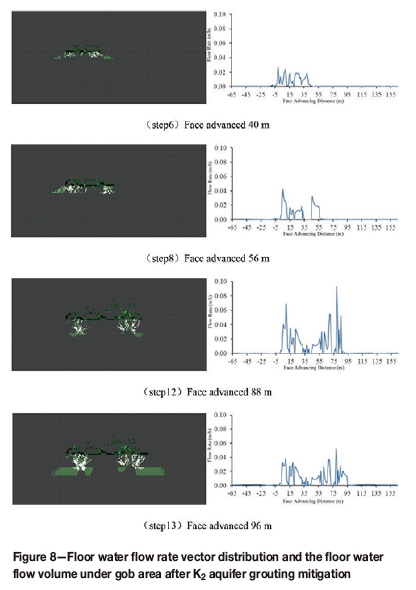
As the face advances, the water flow rate and volume increase under the gob area. When the face advances to 40 m, the immediate roof undergoes the first weighting and the floor water flow rate is relatively small at only 2.58 χ 10-2 m/h. The floor water inrush is mainly from the fracture water in the mining fracture zone of the immediate floor. The water flowing outlets are mainly in the gob area, as shown in Figure 8 (step 6).
When the face advances to 56 m, the floor water flow rate increases to 4.21 χ 10-2 m/h and the water inrush is mainly from the fracture water in the quartz sandstone and fine sandstone layers in the immediate floor. There is an insignificant impact on the water-blocking characteristics of the effective floor aquiclude, as shown in Figure 8 (step 8).
When the face advances to 88 m, the immediate roof has undergone three periodic weightings and the floor damage depth reaches 11 m. The floor water flow rate increases to 9.25 χ 10-2 m/h. The water outlet locations are mostly in the open cut and gob areas. The floor fracture zone still does not connect to the K2 aquifer and no water-conducting path forms, as shown in Figure 8 (step 12).
When the face advances to 96 m, the roof sandstone key strata break and compact the debris in the gob. The water inrush slows and the water flow rate decreases to 5.25 χ 10-2 m/h, as shown in Figure 8 (step 13). At this point, the floor damage depth remains 11 m. The floor fracture zone still does not connect to the K2 aquifer and no water-conducting path forms. The floor aquiclude retains its very good water-blocking characteristics. This result indicates that grouting of the K2 aquifer has significantly improved the total strength of the floor aquiclude and the water-blocking characteristics.
Discussion
Based on the results produced by the two numerical models (before and after K2 aquifer grouting mitigation), it can be concluded that grouting can change the K2 aquifer into an aquiclude or weak aquifer, which not only increases the floor water-blocking capability and the total strength, but also reduces the depth of floor damage. The floor water inrush path can be effectively controlled in order to prevent water inrush from the Ordovician limestone aquifer. The numerical simulation methodology and results provide a scientific basis for the engineering practice of floor grouting mitigation for the purpose of preventing water inrush.
Field experiment on floor grouting mitigation
The numerical simulation results described above were applied using field engineering techniques to the floor of panel 22507 of the no. 5 coal seam at Dong'iahe coal mine. The objectives of the exercise were to improve the water-blocking capability and effective thickness of the floor aquiclude (the K2 aquifer) in order to prevent water inrush hazards and ensuring safe production in the mine.
Floorgrouting mitigation theory
Based on the effective diffusion radius of grout from a single borehole, it is necessary to drill a sufficient number of grouting boreholes into the floor aquifer at the headgate and tailgate entries. When the designed grouting pressure is applied, the grout material will squeeze into aquifer voids, structural fractures, and water-conducting paths, then consolidate or gelatinize, forming an integrated water-blocking structure. The K2 aquifer will be changed into an effective aquiclude or weak aquifer, which will improve the water-blocking capability and the total strength of the floor aquiclude, reduce the amount of water in the K2 aquifer, and ensure the safety of the retreat mining face.
Procedure
Based on the floor strata lithology and Ordovician limestone aquifer properties and the geological and hydrogeological conditions during the development of the panel, it was decided to construct an exploratory drilling site during development and to drill into the floor in order to in'ect grout for the purposes of floor condition mitigation. The grout would fill the floor sandstone fractures and change the aquifer into an effective aquiclude or weak aquifer, enabling safe mining above the confined water level.
Layout of the drilling site
Drilling was conducted at the side of the panel. The grouting area was determined by the length (910 m) and width (115 m) of the longwall panel. Headgate and tailgate entries were constructed with eight drilling sites each; two drilling sites were also located at the open cut area for a total of 18 drilling sites. The drilling sites were numbered from the beginnings of the entries as 1, 3, 5, 7, 9, 11, 13, and 15 for the headgate entry; 2, 4, 6, 8, 10, 12, 14, and 16 for the tailgate entry; and 17 and 18 for the open cut area. The length, width, and height of the drilling sites were 4 m, 4 m, and 3 m, respectively.
Borehole layout
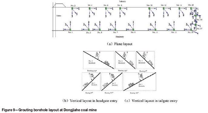
Based on previous underground grouting experience in the Chenghe mining field, the grout diffusion radius was estimated to be 30-60 m. The grouting depth was selected to be 3 m below the level of impact on the K2 aquifer by mining abutment pressure. In order to inject the grout effectively into the K2 aquifer and reinforce it, the grouting boreholes were designed and planned as shown in the plane layout and vertical views in Figure 9.
There were three boreholes at each drilling site. At the headgate entry, the boreholes were laid at angles of 270°, 315°, and 0° in the vertical plane (plane layout) and at 30°, 40°, and 45° in the horizontal plane. At the tailgate entry, the boreholes were laid at 90°, 135°, and 180° in the plane layout and at 30°, 40°, and 45° to the horizontal plane.
All boreholes were drilled and cored according to this design. For boreholes at different depths, three levels of protection casings were installed, i.e., φ 168 at the first level, φ 108 at the second level, and φ 89 at the third level. Pure cement grout was used to seal the boreholes.
Grouting material
In order to ensure effective grouting and water blocking and reduce the engineering costs, clay grout and cement grout were injected into the floor alternately. Pure cement grout was used when necessary.
Grouting effectiveness
The drilling sites and boreholes were constructed and drilled according to the above design requirements. Figure 10 shows the drilling and grouting process. The overall drilling and grouting process for the panel took 344 days and entailed a total drilling distance of 3796.9 m. Grouting of current boreholes and drilling of future borehole were conducted simultaneously, and the total grouting volume was 41 232.75 m3. The injection pressures of all boreholes reached the designed value and the pressure stabilization times satisfied the standards requirements. Underground survey and measurements confirmed that all boreholes in the exploration area had no or very little water outflow.
The water flow rates of the boreholes were around 0-0.5 m3/h, which satisfied the design requirement of 1 m3/h. Rock sampling and electrical surveying were conducted before and after grouting to verify the grouting effectiveness. The test results show that the floor grouting had significant water-blocking effects and that the mitigation project satisfied design requirements. All boreholes were sealed after grouting.
Prior to grouting mitigation, the water inrush flow rate at panel 22507 was estimated to be 200 m3/h; after floor grouting mitigation, the measured rate was reduced to less than 60 m3/h. This represents a saving of up to one million RMB in water drainage cost. The floor-mitigated panel is currently retreat-mined and 375 000 t of coal has been safely extracted, representing an income of about 147.2 million RMB for the company.
Conclusions
A numerical analysis on the simulation of grouting mitigation of the floor of the no. 5 coal seam at panel 22507 of Dong'iahe coal mine was conducted. Based on the geological condition of panel 22507, Rock Failure Process Analysis (F-RFPA2D) software was used to analyse the stability and water-blocking characteristics of the floor aquiclude before and after grouting. The numerical study results were applied at the mine in order to facilitate engineering works, and the proposed mitigation measures employing grouting of the floor of the seam were implemented. As a result, panel 22507 can now be mined safely above the confined water level. This exercise provided valuable experience in preventing water hazards and has resulted in significant economic and social benefits.
Based on the geological condition of panel 22507, numerical analysis using Rock Failure Process Analysis (F-RFPA2D) was used to predict dynamic crack development, expansion, and distribution in the floor aquiclude under the combined effects of seepage and stress field. Mining damage to the floor aquiclude, stress distribution, and seepage features were analysed.
The results produced by numerical simulation of the panel before and after K2 aquifer grouting mitigation demonstrated that grouting mitigation could change the aquifer into an aquiclude or weak aquifer, which not only increases the floor water-blocking capability and total strength, but also reduces the floor damage depth. The floor water inrush path can be effectively controlled in order to prevent water inrush from the Ordovician limestone aquifer. The numerical simulation methodology and results provided a scientific basis for the engineering practice of floor grouting mitigation for the purpose of preventing water inrush.
The numerical simulation results were applied in a field engineering exercise in which floor grouting mitigation was applied to the floor aquiclude of the K2 aquifer with the goal of preventing water inrush hazards and ensuring safe coal production. The injection pressures of all boreholes reached the designed value and the pressure stabilization times satisfied standards requirements. Underground survey and measurements confirmed that all boreholes had zero or minimal water outflow. The water flow rates of the boreholes were around 0-0.5 m3/h, which satisfied the design requirement of 1 m3/h. Rock sampling and electrical surveying were conducted before and after grouting to verify grouting effectiveness, with the test results showing that the floor grouting had significant water-blocking effects and that the project satisfied the design requirements.
The grouting mitigation project solved the problem of water inrush hazard during retreat mining; this effectively reduced the water drainage costs, improved the recovery ratio, and most importantly, ensured the safe mining of the panel. These research results suggested new ideas for mitigating the water inrush hazard at Dongjiahe coal mine and also provided valuable experience for future panel mining above confined water.
Acknowledgements
The authors gratefully acknowledge financial support from National Natural Science Foundation for Young Scientists (41402265). The acquisition of the modelling skills and equipment necessary to complete this project would not have been possible without this support.
References
Chen, X., Xie, W., and Jing, S. 2006. Determination of mechanics parameters of mining induced rock mass for numerical simulation. Journal of Mining & Safety Engineering, vol. 23, no. 3. pp. 341-345. [ Links ]
Duan, H. 2014. Analysis on failure features and failure depth of coal seam floor during mining process. Coal Science and Technology, vol. 42, no. 5. pp. 17-20. [ Links ]
Feng, Q. and Jiang, B. 2015. Analytical solution for stress and deformation of the mining floor based on integral transform. International Journal of Mining Science and Technology, vol. 25, no. 4. pp. 581-586. [ Links ]
Guan, Y., Li, H., and Lu, J. 2003. Research of no. 9 coal seam floor's fracture regularity in Xian-Dewang coal mine. Journal of China Coal Society, vol. 28, no. 2. pp. 121-125. [ Links ]
Jiang, Z.H. 2011. Numerical analysis of the destruction of water-resisting strata in a coal seam floor in mining above aquifers. Mining Science and Technology (China), vol. 21, no. 4. pp. 537-541. [ Links ]
Li, A., Gu, S., and Chen, F. 2013. Theoretical analysis and numerical simulation of destroyed depth of coal seam floor during bearing mining: with seam no. 5 in Dong'iahe Mine, Chenghe Mining Area, Shaanxi as example. Coal Geology & Exploration, vol. 41, no. 4. pp. 56-60. [ Links ]
Li, A., Liu, Y., and Mou, L. 2015. Impact of the panel width and overburden depth on floor damage depth in no. 5 coal seam of Taiyuan group in Chenghe Mining Area. Electronic Journal of GeotechnicalEngineering, vol. 20, no. 6. pp. 1603-1617. [ Links ]
Li, K. and Wang, C. 2003. The technique measuring the stress of rock mass used in the study of the mechanism of the water-inrush from coal floor. Coal Geology & Exploration, no. 3. pp. 31-33. [ Links ]
Li, S., Liu, B., Nie, L., Liu, Z., Tian, M., Wang, S., Su, M., and Guo, Q. 2015. Detecting and monitoring of water inrush in tunnels and coal mines using direct current resistivity method: A review. Journal of Rock Mechanics and Geotechnical Engineering, vol. 7, no. 4. pp. 469-478. [ Links ]
Liu, W., Cao, G., Shen, J., Zhang, L., and Xintai, C.I.B. 2013. Field measurement and simulation research on floor failure depth. Journal of Liaoning Technical University, vol. 32, no. 12. pp. 1585-1589. [ Links ]
Liu, Y. 2008. Numerical analysis of breaking depth of coal floor caused by mining pressure. Journal of Xi'an University of Science of Technology, vol. 28, no. 1. pp. 11-14. [ Links ]
Liu, Z. and Hu, Y. 2007. Solid-liquid coupling study on water inrush through faults in coal mining above confined aquifer. Journal of China Coal Society, vol. 32, no. 10. pp. 1046-1050. [ Links ]
Lu, H., Yao, D., Shen, D., and Cao, J. 2015. Fracture mechanics solution of confined water progressive intrusion height of mining fracture floor. International Journal of Mining Science and Technology, vol. 25, no. 1. pp. 99-106. [ Links ]
Lu, Y. and Wang, L. 2015. Numerical simulation of mining-induced fracture evolution and water flow in coal seam floor above a confined aquifer. Computers and Geotechnics, vol. 67, no. 6. pp. 157-171. [ Links ]
Wang, J.A. and Park, H.D. 2003. Coal mining above a confined aquifer. International Journal of Rock Mechanics and Mining Sciences, vol. 40, no. 4. pp. 537-551. [ Links ]
Wang, K., Wei, A., Chen, Y., and Yue, Q. 2004. Predicting method and its application of water inrush from coal floor based on catastrophe theory. China Safetty Science Journal, vol. 14, no. 1. pp.11-14. [ Links ]
Wang, Y., Yang, W., Li, M., and Liu, X. 2012. Risk assessment of floor water inrush in coal mines based on secondary fuzzy comprehensive evaluation. International Journal of Rock Mechanics and Mining Sciences, vol. 52, no. 6. pp. 50-55. [ Links ]
Jiuchuan, W.E.I., Zhongjian, L., Longqing, S.H.I., Yuanzhang, G.U.A.N., and Huiyong, Y.I.N. 2010. Comprehensive evaluation of water-inrush risk from coal floors. Mining Science and Technology, vol. 20, no. 1. pp. 121-125. [ Links ]
Wu, J., Jiang, Z., and Zhai, X. 2011. Research on controlling of rock mass structure on water inrush from coal seam floor in Huaibei Mining Area. Procedía Engineering, vol. 26. pp. 343-350. [ Links ]
Yang, T., Tang, C., Tan, Z., Zhu, W., and Feng, Q. 2007. State of the art of inrush models in rock mass failure and developing trend for prediction and forecast of groundwater inrush. Chinese Journal of Rock Mechanics and Engineering, vol. 26, no. 2. 268-277. [ Links ]
Yuan, R., Li, Y., and Jiao, Z. 2015. Movement of overburden stratum and damage evolution of floor stratum during coal mining above aquifers. Procedia Engineering, vol. 102. pp. 1857-1866. [ Links ]
Zhang, J. 2005. Investigations of water inrushes from aquifers under coal seams. International Journal of Rock Mechanics and Mining Sciences, vol. 42, no.3. pp. 350-360. [ Links ]
Zhang, J. and Shen, B. 2004. Coal mining under aquifers in China: a case study. International Journal of Rock Mechanics and Mining Sciences, vol. 41, no. 4. pp. 629-639. [ Links ]
Paper received Nov. 2015
Revised paper received May 2016

