


Services on Demand
Article
 English (pdf)
 Article in xml format
 Article references
Indicators

Related links
-
 Cited by Google
 -
 Similars in Google
Share

 Permalink
Journal of the Southern African Institute of Mining and Metallurgy
On-line version ISSN 2411-9717
Print version ISSN 2225-6253
J. S. Afr. Inst. Min. Metall. vol.118 n.3 Johannesburg Mar. 2018
http://dx.doi.org/10.17159/2411-9717/2018/v118n3a14
PAPERS OF GENERAL INTEREST
Prediction of cuttability from rock cutting resistance
V. Raghavan; Ch.S.N. Murthy
Department of Mining Engineering, National Institute of Technology Karnataka, Surathkal, India
SYNOPSIS
The objective of this investigation is to predict rock cuttability from measurements of rock cutting resistance (RCR) during the cutting process and to study the influence of mechanical properties on the depth of cut achieved. Point attack bits with angles of 45°, 50°, 55°, and 65° were used and the experiments were conducted at attack angles of 45°, 55°, and 65°, keeping the rotation speed constant while varying the cutting force and torque during cutting. The depth of each cut was measured and the cut material collected and weighed. The experimental data were compared using an artificial neural network (ANN) and finite element method (FEM) to predict RCR for the measured depth of cut. The results reveal that a 55° attack angle produced the optimum depth of cut.
Keywords: rock cuttability, rock properties, artificial neural network, finite element method, rock cutting resistance.
Introduction
Cutting machines such as shearers, roadheaders, and continuous miners are used extensively throughout the world for the excavation of rock in mining and civil operations. As theory relating to the mechanical excavation of rock has evolved over time, so too has the utilization of these machines, often substituting for traditional drill-and-blast methods, resulting in increased safety and performance and reduced operating costs.
The method by which these rock cutting machines work is influenced by a number of factors (Neil et al., 1994). Machine design, machine power, intact rock properties, and rock mass properties all play a pivotal role in determining the efficiency of the rock cutting process (Karakas et al., 2005). As Roxborough (1987) explained, the engineer has a choice over what size and type of machine to use for a particular excavation, but has no influence over the rock formation that will be encountered without changing the design criteria of the project. Since it is the rock mass, and not machine selection, that governs cuttability, an investigation into the rock mass properties and their effect on cuttability is warranted.
It has been well documented that a number of rock strength characteristics can adversely affect cutting performance (Rostami, 2011). There is an almost linear relationship between rock strength and cutting force required (Hood and Roxborough, 1992). Similarly, it has been found that abrasivity of rock tends to increase with rock strength (Jacobs and Hagan, 2009), and laboratory testing has focused on attempting to find which rock strength properties best describe this relationship. Specific energy is extensively used to evaluate rock cuttability (Tiryaki and Dikmen, 2006). It is a measure of the force required to excavate a unit volume of rock, and hence is a measure of the relative cuttability of a particular rock. McFeat-Smith and Fowell (1977), in their well-known study, correlated rock strength properties with specific energy and found that the cutting performance of cutting machines diminished with specific energy.
Recent studies have focused on an array of properties in an effort to estimate rock cuttability, with strong correlations found between the uniaxial compressive strength and specific energy for a number of different rock types (Speight, 1987). Material hardness, sonic velocity, Young's modulus, and other rock properties that indirectly relate to rock strength have been correlated with specific energy, with varying degrees of statistical significance. To date, however, the most reliable indicator of cuttability has been based on the uniaxial compressive strength of rock.
From a mining perspective, further investigations to confirm the validity and correlation between rock strength parameters and cuttability would be useful in the estimation of machine performance. The ability to predict cutting performance from direct and indirect rock strength measurements would be of potential benefit to the industry, especially for mining operations interested in assessing the relative cuttability of rock. The purpose of this paper is to develop a method to predict the rock cutting resistance and influence of rock strength of samples tested in the laboratory.
Literature survey
Various procedures, processes, and phenomena treated in science and engineering are often described in terms of differential equations formulated by using their continuum mechanics models. Solving differential equations under various conditions such as boundary or initial conditions leads to the understanding of the phenomena and can predict their future state. However, exact solutions for differential equations are generally difficult to obtain. So, numerical methods are adopted to obtain approximate solutions for differential equations. Among these numerical methods, those that approximate continuation with an infinite degree of freedom by a discrete body with finite degree of freedom are called 'discrete analysis' (Stolarski et al., 2006).
Modelling is a useful tool for engineering design and analysis. The definition of modelling may vary depending on the application, but the basic concept remains the same: the process of solving physical problems by appropriate simplification of reality. In engineering, modelling is divided into two major categories: physical/empirical modelling and theoretical/analytical modelling. Laboratory and in situ model tests are examples of physical modelling, from which engineers and scientists obtain useful information to develop empirical or semi-empirical algorithms for tangible application. With the increase in computational speed and power, many numerical models and software programs have been developed for various engineering practices.
The finite element method (FEM) requires the division of the problem domain into a collection of elements of smaller sizes and standard shapes (triangle, quadrilateral, tetrahedral, etc.) with a fixed number of nodes at the vertices and/or on the sides. The trial functions, usually polynomial, are used to approximate the behaviour of partial differential equations at the element level and generate the local algebraic equations representing the behaviour of the elements. The local elemental equations are then assembled, according to the topological relations between the nodes and elements, into a global system of algebraic equations whose solution then produces the required information in the solution domain, after imposing the properly defined initial and boundary conditions. The FEM is perhaps the most widely applied numerical method in engineering today because of its flexibility in handling material heterogeneity, nonlinearity, and boundary conditions, with many well-developed and verified commercial codes with large capacities in terms of computing power, material complexity, and user-friendliness. Due to the interior discretization, the finite domain method (FDM) and FEM cannot simulate infinitely large domains (as are sometimes presented in rock engineering problems, such as half-plane or half-space problems) and the efficiency of the FDM and FEM will decrease with too high a number of degrees of freedom, which are in general proportional to the numbers of nodes (Jing, 2003).
The FEM has been used by Wang (1976), Tang (1997), Kou et al. (1999) and Liu (2002) to simulate fracture propagation during rock indentation or rock cutting. Generally, these models used a stress-based criterion to form cracks normal to the maximum principal stress (tensile stresses are taken as positive) at the element integration points. Failure occurs if the maximum tensile stress exceeds the specified fracture strength. In compression, the models utilized a Mohr-Coulomb failure criterion to form shear cracks at the element integration points. After the cracks have formed, the strains normal to both the tensile and shear cracks are monitored in subsequent time/load steps to determine if the cracks are open or closed. If a crack is open, the normal and shear stresses on the crack face are set equal to zero for a tensile crack.
Wang (1975) developed a general mathematical rock failure model by applying the available finite element technique to established computer code, which allows simulation of the sequence of penetration mechanisms and provides a better description of the failure phases such as initial cracking, crushing, and chipping. Wang (1975) also used the 'stress transfer' method suggested by Zienkiewicz (1968) to convert excessive stresses that an element cannot bear to nodal loads and reapply these nodal loads to the element nodes, and thereby to the system. If a crack is closed, a compressive normal stress can be carried, but the shear stress is limited to a value described by the Coulomb friction model. The analytical results presented in the studies conducted by Wang (1975) show reasonable agreement with experimental observations.
Numerical analysis of the wedge indentation problem was conducted by Huang et al. (1997) using the FLAC software. The numerical analysis indicated that the location of maximum tensile stress (interpreted as the point of crack initiation) moves away from the indentation axis as the lateral confinement increases. They found that a small increase in the confining stress from zero induces a large increase in the inclination of this point on the indentation axis. However, the confinement does not significantly reduce the maximum tensile stress and it hardly influences the indentation pressure.
Carpinteri, Chiaia, and Invernizzi (2004) conducted indentation tests on brittle and quasi-brittle materials and obtained fracture patterns in homogeneous brittle solids by FEM in the framework of linear elastic fracture mechanics. Microstructural heterogeneities were taken into account by the lattice model simulation. Although reality is often much more complex than the theoretical models applied, the study provides interesting indications for improving the performance of cutting tools. The FRANC2D software, developed at Cornell University, was used to simulate fracture in the homogeneous case. This software is able to simulate plane stress, plane strain, as well as axis-symmetric crack propagation in the framework of linear elastic fracture mechanics (LEFM). Carpinteri, Chiaia, and Invernizzi concluded that the cutting performances could be significantly improved by reducing the crushing component and enhancing the chipping ability of the indenters {e.g. by increasing their size or depth of penetration).
Liu et al. (2002) simulated the rock fragmentation processes induced by single and double truncated indenters by the rock and tools interaction code, R-T2D, based on the Rock Failure Process Analysis (RFPA) model. The simulated crack patterns were in good agreement with indentation experiments and a better understanding was gained. From the simulated results, a simple description and qualitative model of the rock fragmentation process induced by truncated indenters was developed. The simulated results reproduced the propagation, interaction, and coalescence process of side cracks induced by the two indenters, and the formation of large rock chips. The authors pointed out that the simultaneous loading of the rock surface by multiple indenters seems to provide a possibility of forming larger rock chips, controlling the direction of subsurface cracks, and consuming a minimum total specific energy.
Wang et al. (2011) examined the rock fragmentation processes induced by double drill bits subjected to static and dynamic loading by a numerical method. Micro-heterogeneities of the rock are taken into account in this numerical model. For the static case, the simulated results reproduced the progressive process of brittle rock fragmentation during indentation. For the dynamic case, numerical simulations represented radial cracks, incipient chips, pulverized zones, and shell cracks. A comparison of the static and dynamic cases showed that dynamic loading can lead to more efficient rock fragmentation. In addition, the numerical results indicated that the dynamic pressure (Pmax) plays an important role in the failure of specimens when two indenters are used. Furthermore, the heterogeneity of the rock can also affect the failure modes of the rock when two indenters are used. Finally, the numerical results demonstrated the effect of the spacing between the indenters on the rock. The numerical code RFPA2D (Rock Failure Process Analysis, 2D) (Zhu and Tang, 2006) was used to consider the heterogeneity of rock and simulate the evolution of dynamic fracture initiation and propagation due to impact loading from double indenters.
Saksala et al. (2013) simulated dynamic indentation with a numerical method. The method was validated by dynamic indentation experiments with single and triple indenters on Kuru granite. The simulation method included a constitutive model for rock and a model, implemented in FEM, to simulate the dynamic bit-rock interaction. The constitutive model, being a combined visco-plastic damage model, accommodated the strong strain-rate dependency of rock via visco-plastic hardening/softening laws both in tension and compression. The authors carried out indentation experiments with single-and triple-button indenters using a set-up similar to percussive drilling. Despite the continuum approach, the model can capture the salient features of the dynamic bitrock interaction involved in dynamic indentation and applications alike. The authors concluded that a fairly good agreement existed between the simulated and experimental results, and that the model could be a useful tool in, e.g. percussive drill design.
Sulem et al. (2002) carried out numerical analysis of the indentation test. They modelled rock as an elasto-plastic medium with Cosserat microstructure and consequently possessing an internal length. The response of the indentation curve to various sizes of indenter as compared to the internal length of the rock was studied in order to assess the scale effect. Using finite element numerical simulations, they concluded that for a material with a Cosserat microstructure, the apparent strength and rigidity increase as the size of the indenter decreases. This scale effect for the strength can reach 15% for a statistical model and 50% for a kinematical Cosserat model when the size of the indenter tool is comparable to the grain size of the rock. The authors concluded that this scale effect is not significantly affected by the condition at the rock-tool interface, and a similar scale effect has been observed experimentally for metals, and ascribed that to the lack of relevant quantitative experimental data for the scale effect in the case of rocks. They suggested that this effect may be important and should be investigated further. The indentation tests constitute an experimental tool for the testing and validation of continuum theories with microstructure and calibration of internal length parameters.
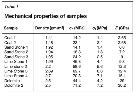
Mechanical properties of rocks tested
The coal and sandstone blocks were collected from Ramagundem Area I, the SCCL, Telangana state. Limestone and dolomite blocks were collected from Chaitanya Industries, JK Cement, Mudhapur, Bagalkot, Karnataka, and also from Andhra Pradesh. Core sample were prepared and tested in the rock mechanics laboratory, Department of Mining Engineering, NITK as per the ISRM standards. The mechanical properties tested were uniaxial compressive strength, Brazilian tensile strength, elasticity modulus, and density. Three readings were taken for each test and averaged - the results are listed in Table I.
Density
Trimmed core samples were used in the determination of natural density. The specimen volume was calculated from an average of several caliper readings and the weight of specimen determined using a sensitive balance. The density was calculated using the following formula: density (g/m3) = mass of the sample/volume of sample.
Uniaxial compressive strength
Uniaxial compressive strength tests were performed on core samples 54 mm in diameter and with a length-to-diameter ratio of 2.5. The stress rate was applied within the range of 0.5-1.0 MPa/s. Load was applied continuously until failure occurred, and the maximum load (in kN) at failure recorded. The UCS of the specimen was calculated by dividing the maximum load carried by the specimen during the test by the original cross-sectional area.
Brazilian tensile strength
Brazilian tensile strength tests were conducted on core samples with a diameter of 54 mm and a length-to diameter ratio of unity. The tensile load on the specimen was applied continuously at a constant stress rate of 200 N/s, such that failure would occur within 5 mm of displacement, until the sample failed. The maximum load (in kN) at failure was recorded. The BTS of the specimen was calculated by dividing the maximum load applied to the specimen by the original cross-sectional area.
Young's modulus
Young's modulus was measured at a stress level equal to 50% of the ultimate uniaxial compressive strength. Loads and axial deformations were recorded at evenly spaced load intervals during the test. Ten readings were taken over the load range to define the axial stress-strain curves. Then, the Young's modulus of the specimen was calculated by dividing the ratio of the axial stress change to axial strain produced by the stress change.
Description of rock cutting machine
The rock cutting machine (Figure 1) was constructed to study the influence of cutting parameters like thrust, torque, and rotational speed on the cutting process.
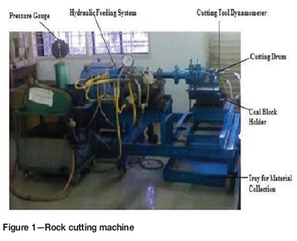
The machine is mounted on a rectangular 1.524 m χ 1.066 m frame with four legs that are mounted on wheels for easy manoeuvering capability. The legs are 0.9738 m in height and are made of a hollow pipe rock into which a 0.0508 m pipe is attached to support the frames. A 2 horsepower motor is attached to a shaft pulley by a belt drive. The cutter head is attached to the shaft by a flange. The cutter head consists of a drum 15.24 cm in diameter, 10 cm in length, and with 12 bits mounted at a span of 8 cm and placed in a spiral configuration. The sample holder is connected to a hydraulic cylinder, which can provide sideways movement during cutting operation, and a material collecting bin. The block holder can accommodate a block of 0.3 χ 0.3 χ 0.45 m in dimension, which is twice the size of the cutting drum.
In laboratory rock cutting, the rotational speed is varied from 225 to 350 r/min, and the thrust from 1.3 to 2.1 kN. During cutting, the cutting force and torque are measured by the cutting tool dynamometer, which is calibrated in the rock mechanics laboratory. The dynamometer is model no. 111285, manufactured by Industrial Engineering Instruments Company (IEICOS), Bangalore, and has specifications force, 5000 N; torque, 50 Nm; speed, 1000 r/min. For each rotational speed and thrust combination, cutting was done for 60 seconds and cutting depth was measured using a vernier caliper. The rocks in the laboratory experiments comprised two types of coal, three types of sandstone, four types of limestone, and two types of dolomite. Despite the sandstone, limestone, and dolomite having different properties from coal, it was found in the experiments that coal offered more resistance to cutting than the rocks, and the rocks were cut, more easily than the coal.
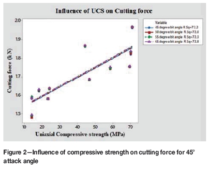
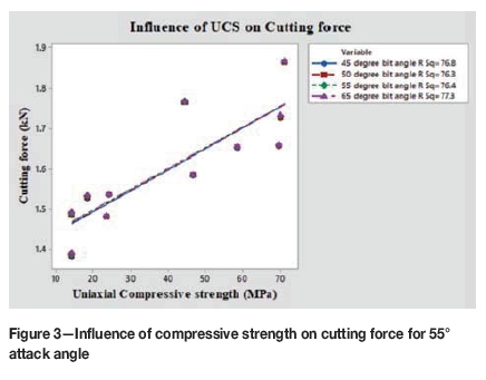
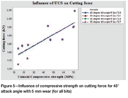
For each combination of rotational speed and thrust, the rock fragments produced were collected and weighed to calculate the specific energy. Attack angles of 45°, 55°, and 65° (the attack angle is the angle between the axis of the tool and the rock) were used. A 60° attack angle was not considered because the performance was found to be same as with a 55° attack angle. For each attack angle, four bit angles - 45°, 50°, 55°, and 65° (the bit angle is the clearance angle given for removal of material in the form of chips) were tested. The influence of wear on cutting rate and specific energy was investigated by conducting experiments with a cutting tool that had been subjected to 5 mm of wear. All the above tests were carried out using all bit-rock combinations, rotational speeds, and thrust settings. The results are shown in Figures 2-9.
Artificial neural network (ANN)
Artificial neural networks have many useful properties and are widely employed in mining and tunnelling applications. The feed-forward back--propagation network was chosen to build a predictive model for cutting force and specific energy in this study. The input layer contained thirteen variables (density, UCS, BTS, Young's modulus, Poisson's ratio, rotational speed, attack angle, bit angle, cutting force, depth of cut, torque, volume broken, and cutting rate) corresponding to the predictors in the model. The single hidden layer had tangent sigmoid transfer function neurons. The output layer has one pure linear neuron corresponding to cutting force and specific energy. The number of hidden neurons was selected as 16. This architecture is known as a useful neural network structure for function approximation or regression problems.
Before implementing the ANN, the data-set was divided into training (70%), validation (15%), and test (15%) subsets. The sets were picked randomly throughout the dataset. The ANN was built, trained, and implemented with the MATLAB neural network toolbox using the Levenberg-Marquardt (trainlm) algorithm for back-propagation.
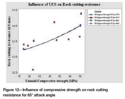
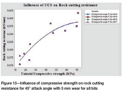
Network errors for the neural network model of depth of cut were measured to check the progress of training. The results for the model were reasonable, since the test set errors and the validation set errors had similar characteristics, and no significant over-fitting occurred. The network responses were also analysed for the neural network model. After unnormal the network outputs, the entire data-set was put through the network and linear regression performed between the network outputs and the corresponding targets for depth of cut. Figures 10 to 13 show the rock cutting resistance predicted by ANN. The neural network model predicted depths of cut very close to those measured and calculated expressed by an R2 value of more than 99% for a 55° attack angle.
Depth of cut prediction by FEM
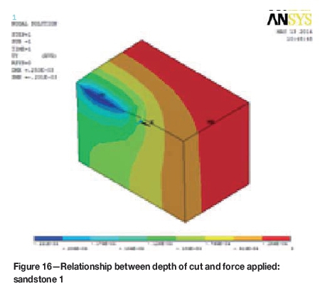
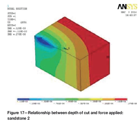
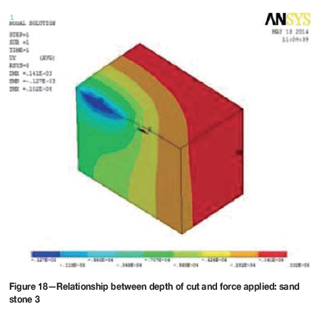
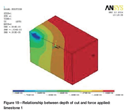
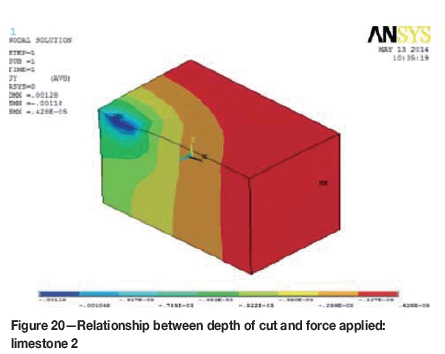
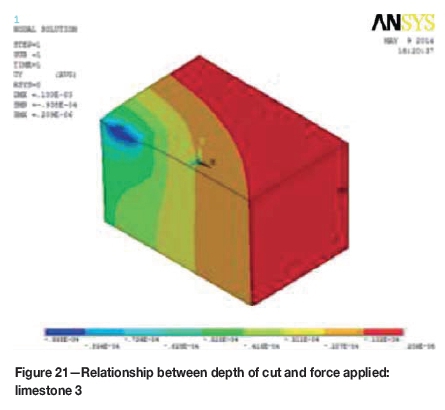
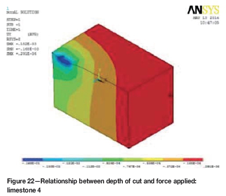
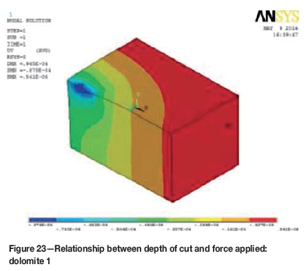
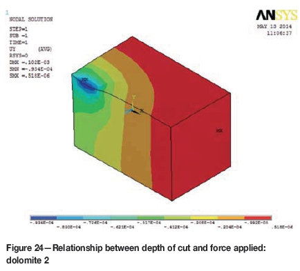
Rock was considered as a homogenous, isotropic, and linear elastic medium in order to simplify the analysis. Because of the experimental difficulties in establishing nonlinear behaviour in the three mutually perpendicular directions, even though a nonlinear analysis programme is available in ANSYS, the present work was limited to elastic analysis.
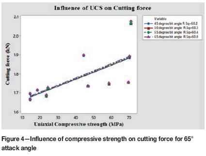
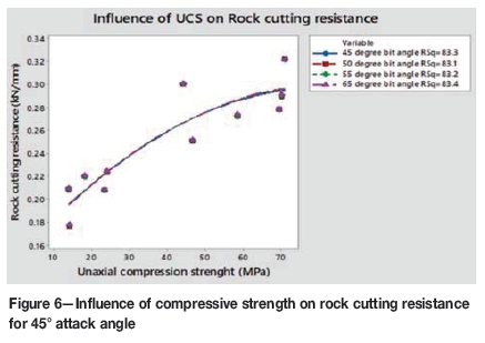
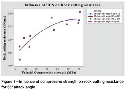
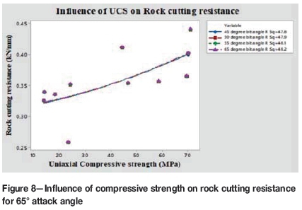
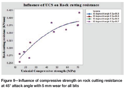
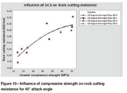
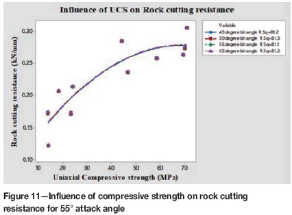
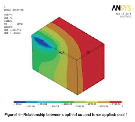
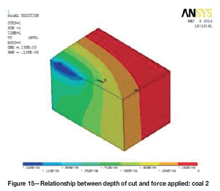
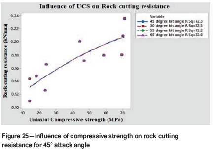
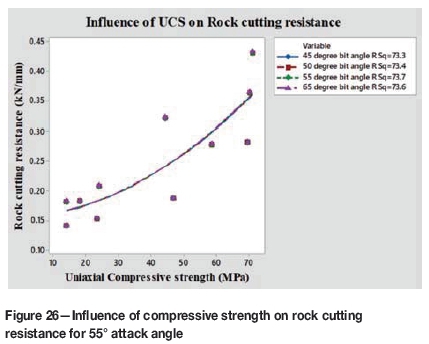
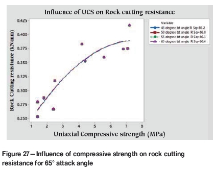
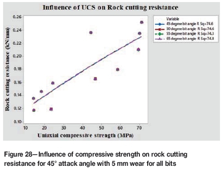
The dimensions of the block were 0.3 χ 0.3 χ 0.45 m and the material properties included Young's modulus, Poisson's ratio, and rock density. Meshing was done, then the load was applied to determine the depth of cut of the rock, loading at the contact plane between the bit and the rock. The relationship between depth of cut and force applied is shown in Figures 14 to 24. Figures 25 to 28 show the influence of UCS of the rock on the cutting resistance.
Results and discussions
Whatever the combined action of cutting parameters that is transmitted through the cutting bits onto the rock, it will be met with resistance offered by the rock. This has been represented in this alternative concept as rock cutting resistance (RCR), which is defined as the force required to achieve a unit depth of cut, and is expressed in kN/mm. In the present investigation, four rock types (coal, sandstone, limestone, and dolomite).were subjected to point attack with bits of 45°, 50°, 55°, and 65° bit angles at 45°, 55°, and 65° attack angles, and at 45° attack angle with 5 mm wear on all bits.
The RCR from the FEM analysis is lower than the values predicted by ANN and those obtained experimentally. In case of FEM analysis, the RCR values are for the ideal rock conditions (isotropic, uniform, homogeneous, linear elastic and devoid of any form of discontinuities), hence the depth of cut achieved was greater than with other two methods, and consequently the RCR values were the lowest.
The RCR values were correlated with the depth of cut as obtained from the laboratory rock cutting experiments for different cutting force values. It is observed that the depth of cut decreases linearly with increasing RCR. However, the rate of decrease in the depth of cut is less at higher cutting forces. The trend is similar irrespective of the method (FEM, ANN, or RCM) employed for determining the RCR.
In order to establish the suitability of the concept of RCR, its dependence on the various rock properties has been presented. It is observed that, irrespective of the method used for determining RCR, the RCR increases linearly with an increase in all five rock properties considered in the investigation. It is observed that the 45°, 65°, and 45° bit angles with 5 mm of wear and at 45° attack angle, the RCR, is much greater than at 55° attack angle. Both FEM and RCM experimental investigations indicate that a 55° attack angle offers more resistance to cutting.
Conclusion
1. The best results were obtained with a 65° tip angle and 55° attack angle.
2. The R2 value predicted by ANN for depth of cut at 55° attack angle is more than 99%, which is less than the experimental value. Both the depth of cut and material cut increase with the specific energy.
3. The R2 values predicted by ANN for cutting force and depth of cut at 45°attack angle is 95%, and at 65° attack angle is less than 90%.
4. The R2 value predicted by FEM for depth of cut at 45°attack angle is 95%, and at 65° attack angle is less than 90%.
5. The cutting rate decreases with increasing compressive strength. The maximum cutting rate achieved is at an attack angle of 55°.
6. Even though only a limited variety of rocks were tested in this investigation, the results are encouraging. It is suggested that further investigations be carried in this direction once the mechanical properties of the rocks (like density, UCS, UTS, Young's modulus, and Poisson's ratio) are available, to establish the RCR for different bit-rock interactions. Once this data is available, the depth of cut in rock cutting can be reasonably predicted from the RCR of a particular bit-rock combination, instead of using complicated test procedures to evaluate the cuttability of rocks without actual rock cutting tests.
References
Brown, ET. 1981. Suggested methods for determining the uniaxial compressive strength and deformability of rock materials. Rock Characterisation Testing and Monitoring - ISRM Suggested Methods. Pergamon Press. [ Links ]
Carpinteri, A., Chiaia, B., and Invernizzi, S. 2004. Numerical analysis of indentation fracture in quasi-brittle materials. Engineering Fracture Mechanics, vol. 71, no. 4. pp.567-577. [ Links ]
Hagan, P. 1990. Some aspects of the application of high pressure water jets to rock cutting. PhD thesis, University of New South Wales. [ Links ]
Hood, M.C. and Roxborough, F. 1992. Rock breakage: mechanical. SME Mining Engineering Handbook. Hartman, H.L. (ed.). Society for Mining, Metallurgy and Exploration, Littleton, Co. pp 680-721 [ Links ]
Jacobs, N. and Hagan, P. 2009. The effect of stylus hardness and some test parameters on the Cerchar Abrasivity Index. Proceedings of the 43rd US Rock Mechanics Symposium, Asheville, NC. American Rock Mechanics Association, Alexandria, VA. [ Links ]
Jing, L.A. 2003. A review of techniques advances and outstanding issues in numerical modelling for rock mechanics and rock engineering. International Journal of Rock Mechanics and Mining Sciences, vol. 40. pp. 283-353. [ Links ]
Karakas, A.R, Bilgin, N., Tumac, D., Feridunoglu, C., and Akgul, M. 2005. The performance of a roadheader in high strength rock formations in Kücüksu tunnel. Proceedings of the International World Tunnel Congress and the 31st ITA General Assembly, Istanbul. International Tunnelling Association. [ Links ]
Kou, S., Lindqvist, P.A., Tang, C., and Xu, X. 1999. Numerical simulation of the cutting of inhomogeneous rocks. International Journal of Rock Mechanics and Mining Sciences, vol. 36, no. 5. pp. 711-717. [ Links ]
McFeat-Smith, I. and Fowell, R. 1977. Correlation of rock properties and the cutting performance of tunnelling machines. Proceedings of Rock Engineering, University of Newcastle upon Tyne. British Geotechnical Society. pp. 581-602 [ Links ]
Neil, D.M., Rostami, J., Özdemir, L., and Gertsch, R. 1994. Production Estimating Techniques for New Mexico. SME, New York. pp. 1-7. [ Links ]
Rostami, J. 2011. Mechanical rock breaking. SME Mining Engineering Handbook. Darling, P. (ed.). Society for Mining, Metallurgy and Exploration, Littleton, Co. pp. 415-434. [ Links ]
Roxborough, F.F. 1987. The role of some basic rock properties in assessing cuttability. Proceedings of the Seminar on Tunnels: Wholly Engineered Structures, Sydney, Australia. The Institute of Engineers Australia and AFCC. [ Links ]
Saksala, T., Gomon, D., Hokka, M., and Kuokkala, V.T. 2013. Numerical modeling and experimentation of dynamic indentation with single and triple indenters on Kuru granite. Rock Dynamics and Applications - State of the Art. Zhao, J. and Li, J. (eds.). Taylor & Francis. pp. 415-421. [ Links ]
Speight, H.E. 1987. The application of drag pick rock cutting machines. in Proceedings of the Conference on Equipment in the Minerals Industry: Exploration, Mining and Processing, Kalgoorlie, Western Australia. Metalliferous Mining. Australasian Institute of Mining and Metallurgy, Melbourne. pp. 137-147 [ Links ]
Tang, C.A. 1997. Numerical simulation of progressive rock failure and associated seismicity. International Journal of Rock Mechanics and Mining Sciences, vol. 34. pp. 249-262. [ Links ]
Tiryaki, B. and Dikmen, A.C. 2006. Effects of rock properties on specific cutting energy in linear cutting of sandstones by picks. Rock Mechanics and Rock Engineering, vol. 39, no. 2. pp. 89-120. [ Links ]
Wang, J.K. 1976. Bit penetration into rock - A finite element study. International Journal of Rock Mechanics and Mining Sciences, vol. 13. pp. 11-16. [ Links ]
Zienkiewicz, O.C. 1968. Continuum mechanics as an approach to rock mass problems. Rock Mechanics in Engineering Practice. Stagg, K.G .and Zienkiewicz, O.C.(eds.). Wiley. Chapter 8, pp. 237-73. [ Links ]
Zienkiewicz, O.C. 1968. The Finite Element Method. McGraw-Hill, London. [ Links ] ♦
Paper received Jun. 2017
Revised paper received Dec. 2017

