


Services on Demand
Article
 English (pdf)
 Article in xml format
 Article references
Indicators

Related links
-
 Cited by Google
 -
 Similars in Google
Share

 Permalink
Journal of the Southern African Institute of Mining and Metallurgy
On-line version ISSN 2411-9717
Print version ISSN 2225-6253
J. S. Afr. Inst. Min. Metall. vol.118 n.3 Johannesburg Mar. 2018
http://dx.doi.org/10.17159/2411-9717/2018/v118n3a13
PAPERS OF GENERAL INTEREST
Silicomanganese production at Transalloys in the twenty-tens
J.D. SteenkampI; P. MaphuthaI; O. MakwarelaI; W.K. BandaI; I. ThobadiI; M. SitefaneI; J. GousII; J.J. SutherlandII
IMintek, Randburg, South Africa
IITransalloys, eMalahleni, South Africa
SYNOPSIS
Transalloys is currently the largest producer of silicomanganese in Africa, with its smelter complex based outside the town of eMalahleni, in the Mpumalanga Province of South Africa. It operates five open submerged arc furnaces and produces an alloy containing > 16% Si, < 2% C, and > 65% Mn. Manganese ore is the main source of manganese units, supplemented by dust and alloy fines recycled into the furnace as briquettes. Transalloys has mature technology and systems in place, which are described in more detail in this paper.
Keywords: silicomanganese, submerged arc furnace, Transalloys.
Introduction
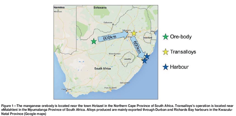
Transalloys is currently the largest producer of silicomanganese (SiMn) in Africa. Its smelter complex is based outside the town of eMalahleni, in the Mpumalanga Province of South Africa (Figure 1). Transalloys was commissioned in the 1960s as an integrated high-carbon/low-carbon ferrochromium plant based on the Perrin process, and converted to SiMn production in 1967 due to constraints in the ferrochrome market (Basson, Curr, and Gericke, 2007; Bezemer, 1995). Currently, the installed production capacity is 180 kt/a saleable SiMn. The majority of this is exported via Durban and Richards Bay harbours.
High-level process flow
The business strategy followed at Transalloys is that of a high-volume, low-margin operation. Plant operations consist of five furnaces, operated 24 hours per day, 365 days per year (including maintenance), by 280 permanent employees, with up to 120 contract employees on site at any given time.
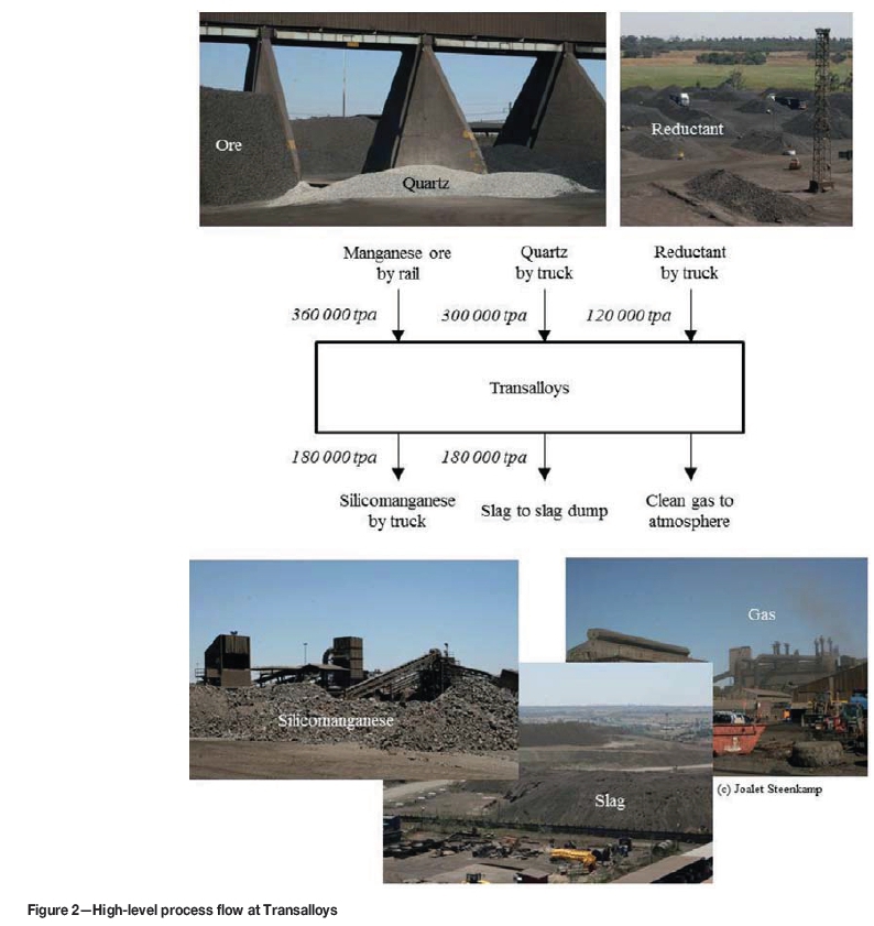
The high-level process flow at Transalloys is summarized in Figure 2. SiMn is produced by carbothermic reduction of manganese-bearing ore sourced from the Kalahari Manganese Field in the Northern Cape Province, and quartz from South African producers. The main source of carbon is bituminous coal from South African coal mines, supplemented with imported coke. The SiMn is produced primarily for the export market, and is exported via Richards Bay harbour. The slag produced is discarded on slag dumps, and process off-gas vented to the atmosphere after cleaning using a specification of 2-30 mg/Nm3. The remainder of the paper addresses the process flow and major equipment in more detail, as well as metallurgical considerations, where applicable.
Product description
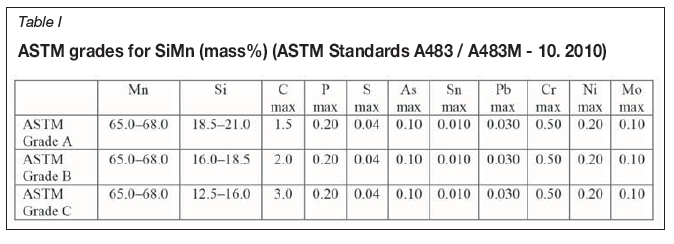
The chemical composition of SiMn produced at Transalloys is typical of ASTM grade B (ASTM Standards A483 / A483M - 10. 2010) (Table I). The product size ranges, in comparison with the ASTM specifications, are summarized in Table II.
Process description
A simple schematic of the operation, on which the description is based, is provided in Figure 3.
Raw material
The feed to the furnaces comprises a blend of raw materials: manganese ores, coal and coke, quartz, SiMn alloy fines, Mn-bearing briquettes, and lumpy spillages. Depending on the composition of these raw materials, the recipe is adjusted to produce SiMn containing between 15 and 16.5% Si, 65 and 67% Mn, and a maximum of 2% C.
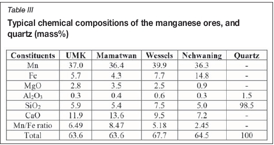
The primary source of manganese in the blend is manganese ores, which are sourced from a number of mines near Postmasburg and Kuruman in the Kalahari region of the Northern Cape Province - United Manganese of Kalahari (UMK), Mamatwan, Wessels, and Nchwaning. The ores are delivered by railway, and have a required size range of -75 + 6 mm. Ore chemistry varies, as indicated in Table III. The mineralogy of manganese-bearing ores from the Northern Cape is complex (Chetty, 2008; Chetty and Gutzmer, 2008). Iron can be present in the divalent and trivalent states and manganese in divalent, trivalent, and even tetravalent states. That is the reason why Fe and Mn assays are typically reported as the zero valent state, as is the case for Table III.
The selection the ore blend fed into the furnaces is driven by techno-economic factors: Ore with 37% Mn forms the baseline, with the selection being based on cost of ore per ton alloy produced. Higher grade ore is added to increase the Mn grade of the SiMn product.
Other sources of manganese are manganese ore spillages from the feed system and reclamation area and surplus SiMn alloy fines (3 mm) from the metal crushing plant. The briquettes have a Mn content of 35%. The recycled SiMn alloy fines, material for which no market exists, improve the production capacity of the furnaces. The -6 mm SiMn alloy fines from the metal recovery plant and from the crushing plant are sent to the briquetting plant as discussed in following sections.
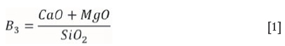
The primary source of silicon in the blend is quartz, the typical composition of which is indicated in Table III, although both the manganese-bearing ores and the reductants also contain some SiO2. Quartz is sourced from two local suppliers around Gauteng and delivered by truck. The quartz is also added to adjust the basicity (B3, defined in Equation [1]) of the slag. Slag basicity is controlled to manage Si recovery.
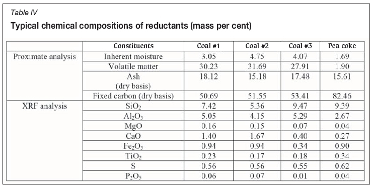
The sources of carbon - required for the reduction of manganese, SiO2, and iron oxides - are coal from a number of coal mines around Mpumalanga and Gauteng and pea coke, sourced mainly from China but also reclaimed at the reclamation area as discussed below. All reductants are delivered by truck. As indicated in Table IV, the fixed carbon content of the coal is significantly lower than that of the coke. Yet, coal is the preferred source of carbon due to its significantly lower cost. Also, it is speculated that the methane gas that is generated during devolatilization of coal will improve the prereduction of the ore in the upper part of the furnace, and this is potentially a useful topic to be researched at the laboratory scale.
Raw material receiving and storage area
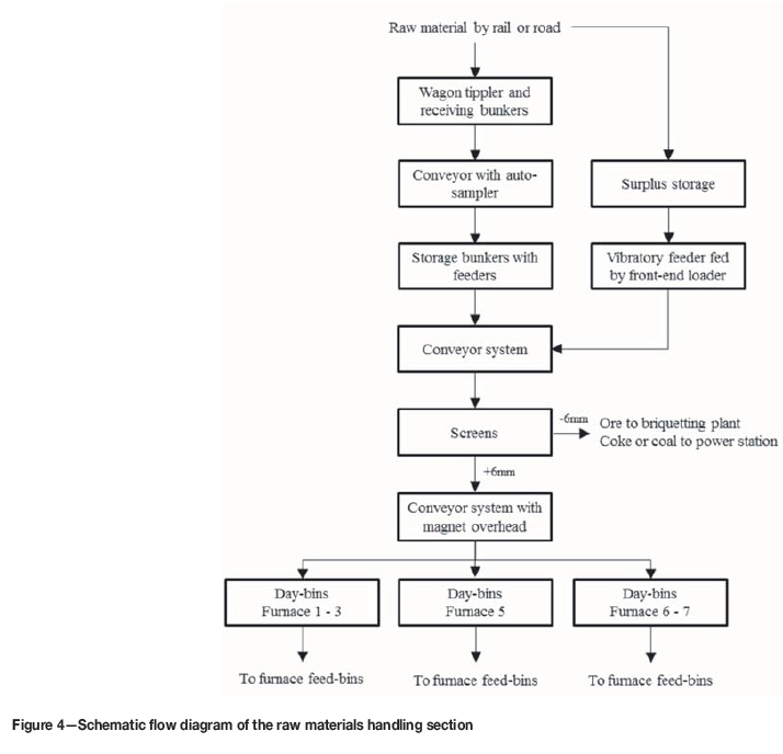
The flow of raw materials through the raw material receiving and storage area is summarized schematically in Figure 4.
The wagon tippler is the main receiving point for raw materials delivered by railway (manganese ores) and road (quartz and reductants). Railway wagons arriving are positioned over the wagon tippler table and rotated to discharge material into four underground hoppers. Raw materials delivered by side-tipper trucks are also discharged into the hoppers, provided that there are no train wagons lined up at the wagon tippler at the time of delivery; alternatively, the trucks are unloaded at specific storage bunkers. Trucks pass through a weighbridge before and after unloading to determine the quantity of material delivered for contractual purposes.
From the wagon tippler hoppers, raw materials are discharged by vibratory feeders onto a conveyor belt, and transported to specific storage bunkers. The conveyor belt has a mobile tipper car that elevates the belt, and discharges material through a chute into a specific bunker. An operator controls the movement, and position, of the tipper car using an automated control system. An automatic sampler positioned along the conveyor belt takes representative samples of material from the conveyor, and discharges the sample into a chute which feeds it into a sample bag for collection. The sample is taken to the laboratory for chemical characterization by X-ray fluorescence (XRF), reductants by LECO (proximate analysis), and physical characterization (particle size distribution) for contractual purposes.
There are five storage bunkers, two allocated for the storage of manganese ore, two for coal, and one for quartz. Other raw materials are stockpiled alongside the feed system and fed to the conveyor system via a vibratory feeder, using a front-end loader. From the storage bunkers, raw materials are directed onto a conveyor system; the quantity of material to be discharged is dependent on the amount of material required to fill the day-bins. The conveyor system feeds raw materials onto two double-deck screens positioned in parallel, with the specific purpose of removing the -6 mm fraction to ensure gas permeability of the burden in the submerged arc furnace (SAF). The -6 mm fraction is discharged from the screens through a hopper, collected, and sent to the briquetting plant in the case of manganese ores, and to local power stations in the case of coal or coke fines.
The +6 mm fraction is discharged via a vibratory feeder onto a conveyor system that transfers the raw materials to the day-bins. A magnet that scavenges metallic objects, i.e. metal shavings, nails, and wire from the feed material, is suspended above the conveyor belt. There are three sets of day-bins from where raw materials are batch-fed into the furnace feed-bins. The first set of day-bins, consisting of 12 bins in succession, feeds raw materials into the feed-bins of furnaces 1 and 3. The second set of day-bins, with 12 bins in pairs, feeds raw materials into the feed-bins of furnace 5. The last set of day-bins, with 14 bins in pairs, feeds raw materials into the feed-bins of furnaces 6 and 7. Each bin is a vertical cylinder made of steel with a conical outlet at the bottom to discharge material onto the conveyor belt. The bins have capacities ranging from 76 m3 to 190 m3 to accommodate the raw materials required for the 24-hour operation of each furnace at maximum throughput. Belt weighers are installed at various sections under the conveyor belts to monitor raw material feed rates and quantities.
A control room operator, based at the delivery station, monitors the quantities of material delivered by rail or truck, and the filling of the day-bins in terms of material type, refill rates, and quantities. The batching and conveying of raw materials from the day-bins to the furnace feed-bins is controlled by the control room operator of each specific furnace.
Briquetting plant
The flow of materials through the briquetting plant is summarized in Figure 5. The feed materials for the briquetting process comprise manganese ore fines, briquette fines, off-gas dust, and SiMn fines, generated at the alloy handling area and recovered at the metal recovery plants. The fines are fed into three hoppers, from which feed materials are batched in different quantities and conveyed to a mixing drum, where they are mixed with binders and water to form a homogenous product. The materials are blended in batches of 800 kg. The mixture is then conveyed at a controlled rate to a briquetting machine, where it is compressed in a die to form briquettes with uniform shape and size. The briquettes are pillow-shaped with a typical size of 37 χ 54 χ 42 mm.
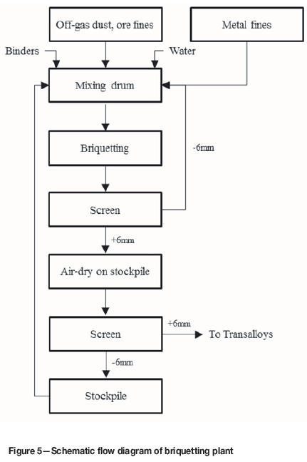
The feed materials are mixed in different ratios to meet the grade, typically 35% Mn, specified by Transalloys. The briquetting machine has a production capacity of 7 t/h. The green briquettes are screened to remove -6 mm fines, which are recycled back to the briquetting machine, and sampled for compression tests. The compression test gives an indication of the strength of the green briquettes. A manual hydraulic pressure test machine is used for this purpose. The rest of the green briquettes are stored, cured for one week (depending on the weather), screened again, and sampled for semiquantitative XRF analysis. The dry briquettes are then transported to the furnaces, and the fines stockpiled and recycled back to the briquetting plant as feed material.
The briquetting plant produces 4500-5500 t of briquettes per month, which is around 10-15% of the feed to the furnace.
Reclamation
The reclamation area was established to recover saleable products from old spillage dumps arising from past operations at Transalloys. The area has been in operation since 2015 and supplies Transalloys with coal, a coal and coke blend, and UMK and Wessels-type manganese ores. The use of spirals was established by a third party as the best practical technique to separate these material streams from the dumps.
Smelting
At Transalloys, silicomanganese is produced in five open submerged arc furnaces (SAFs) of circular design, with three Söderberg electrodes positioned in equilateral arrangement (Figure 6). Two 7 MVA furnaces (Basson, Curr, and Gericke, 2007) previously utilized in the production of mediumcarbon ferromanganese (Barcza and O'Shaughnessy, 1981) have been decommissioned and demolished.
Details of the installed operational furnaces are given in Table V.

Figure 7 depicts a schematic flow diagram of one of the furnaces, showing inputs and outputs. Transalloys uses a blend of manganese ores, briquettes, quartz, coal, coke, and recycled material, the recipe being based on mass and energy balance calculations as well as the material costs. Quartz is used partly as raw material for producing metallic silicon in the SiMn and also as flux. The recycle stream comprises the spillages collected around the plant and the SiMn fines generated in the alloy crushing plant.
Each furnace has about 10 to 16 dedicated primary bins containing raw materials. The mass balance recipe is batched from these bins into the weigh hopper before being transferred to the furnace bins. The final feeders are positioned at different places such that the feed material can be evenly distributed within the furnace. The final feeders in the middle of the furnace (between the electrodes) have a larger capacity than those on the sides because the consumption of the burden is higher in the middle. The transferring of material from one bin to the next is done by means of belt conveyers. There is a sequence followed to ensure mixing such that the blend of material going into the final feeders is homogeneous. Thereafter, the material in the final feeders is fed into the furnace in a batch system, the frequency of feeding depending on the furnace conditions such as burden level.
The top of the burden in the submerged arc furnaces at Transalloys is open to the atmosphere, and this furnace design is often referred to as 'open'. The furnace roof is completely separated from the furnace shell and the gap between the roof and shell is utilized for rabbling and also for visual inspection of the burden. The burden level must at all times be just above the furnace sill and level throughout. To ensure this, rabbling of the burden is conducted on a regular basis to achieve two main objectives: (1) levelling of the burden, and (2) improving burden permeability. Levelling is needed to minimize heat losses, as well as losses of Mn and Si vapour and fines. Simultaneously, ensuring burden permeability is important to avoid furnace blow-outs, which occur primarily as a result of diffusion of gases through the burden being hindered. Other causes of furnace blow-outs include high slag levels in the furnace, electrode position, and slag basicity resulting in a viscous slag (Muller and Steenkamp, 2013).
An insulating refractory design philosophy is followed in which the intention is to design the hot face refractory material to be chemically compatible with the process material. Water cooling is applied to the shells of the two larger furnaces only to protect the steel shell, and not to form a freeze lining of process material on the hot face of the refractory, as is done in conductive lining designs (Steenkamp, 2014). The hearth refractory in a SiMn furnace typically includes one of two high-wear areas (Steenkamp, Pistorius, and Tangstad, 2015). The effects of carbon undersaturation of the alloy (Steenkamp, Pistorius, and Muller, 2016), distance between the tap-hole and the hearth (Ishitobi, Ichihara, and Homma, 2010), electrode pitch circle diameter power intensity, and hearth power intensity on refractory wear rate will potentially be an interesting investigation (summarized in Table VII).

The electrode pitch circle diameter power intensity (PITherth) depends on the operating power (OP) and the electrode pitch circle diameter (PCD), according to Equation [2]. The hearth power intensity (PITheank) depends on the operating power (OP) and the internal diameter of hearth refractory (IDH), according to Equation [3].

The electrical parameters for each furnace are presented in Table VIII. Furnaces 5 and 7 are resistance controlled using Mintek's Minstral™ software, while the other three furnaces are current controlled. There is a substantial difference in the operating currents of furnaces 5 and 7 and those of the other furnaces, which operate at lower power levels. The difference in operating resistance of all furnaces is marginal, implying that the difference in operating power is due to the different operating currents.

As aforementioned, the feeding mechanism is a batch system. Therefore, the feed rates are not captured instantaneously; instead, the feed mass is recorded and consolidated at the end of each production day (24 hours), which can be translated to a daily rate. The control systems of the furnaces focus only on the electrical operation. The smaller furnaces are controlled by current (I, kA), and each has a single three-phase transformer. The larger furnaces are controlled based on electrode-to-bath resistance (R, mQ). Both systems regulate the electrode holder position to maintain the respective set-points, although the use of resistance control mitigates the problem of electrode current interaction caused by the common neutral point within the molten bath (Barker et al., 1991). On furnaces 1, 3, and 6 (current control) the transformers are tapped up and down automatically to maintain the desired power input. On furnaces 5 and 7 (resistance control), the transformers are tapped automatically by the Minstral™ control system, which enables the transformers to be tapped differentially so as to optimize the power input within the specified circuit limitations (Brereton-Stiles, Rennie, and Moolman, 1999).
Owing to the high currents needed in SAF production of SiMn, Söderberg self-baking carbon electrodes are used at Transalloys, which are prepared by welding cylindrical casings and inserting the electrode paste cylinders. The pressure rings force the contact shoes (which are responsible for the supply of current to the electrode) against the steel cylinder and hold the electrode in place. The jacks can be either pneumatic or hydraulic and are responsible for controlling the slipping of the electrode. The electrode paste melts in the casing and starts to bake at a temperature of around 450 to 500°C. Above these temperatures the electrodes are transformed into solid graphite and become electrically conductive, and the steel casings melt and become part of the charge mix.
The electrode consumption is monitored by using manual readings. The slip calculator provides the operator with the length (in centimetres) of electrode that needs to be slipped, and this is compared to the actual slipped centimetres. Electrode slipping is done hourly and the control room operator manually monitors electrode consumption every four hours. Note that the operator will not slip if the electrode hasn't been properly baked yet, which may cause a difference between the calculated and actual slipped values. The liquid and solid level measurements are used as guidelines to the number of electrode paste bags and cylinders to be added to maintain the liquid level in the appropriate range. Leakage of paste from the casing due to fast slipping and the electrode not being baked properly is termed a green break. Thermocouples allow easy identification of green breaks in furnaces 5 and 7, while visual inspection is done on furnaces 1, 3, and 6.
Tapping occurs every four hours at all furnaces. Although some of the furnaces have bi-level tap-holes installed (one dedicated to metal tapping, the other to slag tapping) all furnaces are operated with single-level tap-holes, i.e. metal and slag are tapped simultaneously from the metal tap-hole. Tap-holes are drilled open and closed using mudguns on all furnaces; tap-holes are lanced open only when difficulties with drilling are experienced, i.e. metal frozen in the tapping channel. The metal and slag flow along a 4-5 m long launder into a refractory-lined ladle. Due to differences in specific gravity, metal settles at the bottom of the ladle and slag overflows into a slag pot. The slag that remains on top of the metal is skimmed off onto the floor, using a scraper.
Alloy processing
After scraping off any slag remaining in the ladle, the ladle is weighed (to determine the liquid alloy content by difference), and cast into casting pits lined with SiMn fines (see Figure 8a). The SiMn fines are also used as an embankment around the casting pits to contain the liquid alloy. A layer cast from one ladle is 40 mm thick, on average. As a layer of alloy is allowed to solidify before the next layer is cast onto it, the layers remain separate. This ensures that when the material is removed, the alloy breaks easily into pieces 40 mm thick. The cast alloy is allowed to cool and solidify before being lifted and moved by front-end loader to the alloy stockpile (Figure 8b). The alloy is transported from the stockpile by front-end-loader to the alloy handling plant for further processing.
The stockpiled material is fed into the crushing and size classification plant where different product sizes are produced (Figure 9). The alloy first passes over a grizzly screen. The -76 mm material from the screen is fed to a multiple deck screen where three product sizes are produced: -76 +50 mm, -50 +12 mm, and -12 +3 mm. The -3 mm size material is classified as fines, which are not saleable; they are stockpiled for use on casting beds and in the briquetting plant. The +76 mm material from the grizzly screen is fed to a jaw crusher which produces -80 mm material. The jaw crusher product is fed to another multiple deck screen which produces +76 mm oversize material, -3 mm fines, a -12 +3 mm product, and -76 +12 mm material. The -3 mm fines are added to the fines stockpile, the -12 +3 mm product size is added to the similar size product from other screens, and the -76 +12 mm size class is fed via a vibratory feeder onto the third multiple deck screen. The third screen produces the -3 mm fines, which are added to the fines stockpile, and three product sizes: -12 +3 mm,-50 +12 mm, and -76 +50 mm. Each day's production of +76 mm material from screen 3 is weighed and stockpiled. This stockpile (+76 mm) is accumulated for a month and processed at the end of the month separately to produce different product sizes. The daily production of different size products is accumulated, weighed, and the materials stored in the products bunkers. The products are transported daily to the port in Richards Bay.
Slag
Slag that flows out of the ladle into the slag pot is transported to the slag stockpile with Kress carriers. The slag is not further processed because the level of entrained SiMn is very low and cannot be economically recovered. Slag that is scraped off the alloy ladle onto the floor is collected daily and taken to the metal recovery plant. A significant amount of metal is entrained in this slag because the scraping process removes the interface alloy layer along with the slag, and thus the metal must be recovered. Spillages from the tapping hall are also collected from the tapping floor and taken to the metal recovery plant along with the scraped slag.
Metal recovery plant
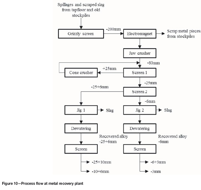
The metal recovery plant processes 200 t/h of slag-based feed material which has a SiMn alloy content of about 5%. The recovered alloy which is separated into different product sizes (Figure 10). The feed material consists of the scraped-off slag and the spillages from the tapping hall, as well as material from old slag stockpiles. The material is first fed onto a grizzly screen, and the oversize material (+200 mm) is broken using a jackhammer and returned to the grizzly screen. The undersize material first passes an electromagnet which removes magnetic metallic pieces. The nonmagnetic material is weighed on a load cell on the conveyer belt immediately after the magnetic separation step. The weighed material is fed to a jaw crusher. The jaw crusher produces -80 mm material which is fed onto a double deck screen. The +25 mm oversize from the first screen is fed into a cone crusher where it is crushed further and recycled to the first screen. The -25 mm undersize material from the first screen goes to the second screen, where it is separated into a -25 +6 mm oversize and a -6mm undersize stream. The two final crusher product streams are sent to separate jigs where differences in the densities of the liberated metal particles and the slag are exploited to separate them and recover the metal. The metal recovered from the -25 +6 mm jig feed is dewatered and fed onto a screen where it is separated into two product sizes; -25 +10 mm and -10 +6 mm. The metal recovered from the -6 mm jig feed is also dewatered and fed onto a separate screen where the -6 +3 mm product size is separated from the -3 mm fines. The three products (-25 +10 mm, -10 +6 mm, and -6 +3 mm) are either sold directly or returned to the metal processing section, where they blended with the appropriate cast metal processing plant product, i.e. the -25 +10 mm metal recovery product is blended with the -50 +12 mm final product size. The -3 mm fines are returned to the main plant where they are used in the briquetting plant.
Off-gas
The off-gas treatment plant's main equipment comprises stacks, a gas duct, trombones, cyclones, main fan, compartments, pneumatic blower, and the silo. These are fully integrated in a logical sequence to ensure that the dustladen off-gas from the furnace is cleaned to produce a dustfree off-gas and recover the dust, which contains significant quantities of manganese and silicon and which serves as part of the briquette recipe. The off-gas plant arrangement is shown in Figure 11.
The dust-laden off-gas first passes through the four furnace stacks at an average velocity of 15 m/s. It then is further carried through the stacks to a single, horizontal gas duct, which under normal furnace conditions operates at a temperature between 340-350°C. The main fan draws the dust-laden gas from the furnace. The dust-laden gas is then cooled in the S-shaped trombone, the sensible heat of the gas passing to the shell of the trombone which is cooled by the external ambient air. The main function of the trombone is to reduce the temperature of the dust-laden gas from about 320°C to 220°C, thus minimizing the possibility of burning out the bag filters in the baghouse.
As a temperature control measure, a dilution damper is installed directly after the trombones with a fully automated control system so that if the temperature of the dust-laden off-gas is higher than desired, further cooling is automatically undertaken. The dilution damper immediately opens at a temperature of 260°C, allowing cooler air to flow in. Furthermore, a higher limit of 280°C is setup as a final control measure, and should the temperature exceed this setpoint, the main fan immediately turns off and the stacks open to allow for further cooling.
Two cyclones are used for each furnace. The purpose of the cyclones is to remove the coarser dust fraction from the off-gases. This reduces the overall dust load to the baghouse compartments and also minimizes damage to the steel shells due to erosion by coarser dust particles.
The off-gas is further treated in the baghouse to remove fine dust and produce a dust-free off-gas. The baghouses of furnaces 5 and 7 have 12 compartments, that for furnace 6 has 8 compartments, and furnaces 1 and 3 share a baghouse with 8 compartments. Each compartment consists of two dampers at the front (the main and re-inflate damper) and a single reverse damper at the back. The bag filters, which are open at the bottom and closed at the top, lie on the top of the compartment. In the compartment, filtration occurs first when the main and re-inflate dampers open to allow the dust-laden off-gas to enter the compartment. At this stage the reverse damper, which applies negative pressure, is closed. During filtration, dust enters the bottom part of the bag filters and is trapped, allowing clean gas to pass through; some of the dust falls to the bottom-most part of the compartment where the hoppers are stationed. Cleaning of the filter bags, which usually takes 30 seconds, follows filtration; in this stage both front dampers are closed while the reverse damper is opened to promote removal of the remaining adhering fine dust from the bag filters. In a filtration-cleaning sequence, only one compartment is offline for cleaning at a time while the remaining compartments are online for filtration.
The dust-free off-gas escapes to the atmosphere at a temperature of approximately 80°C. The gas is believed to consist largely of CO2, as back-calculated from the carbon inputs to the furnace. Transalloys holds an atmospheric emission license from the Department of Environmental Affairs in terms of the Air Quality Act of 2004 (Act No. 39 of 2004).
The fine dust is directed by the pneumatic blower to the silo, from which it is collected by a truck two or three times a day, the average mass being 1.8 t per truck. Both the cyclone underflow and compartment dust are taken to the briquetting plant to serve as part of the briquette recipe.
Acknowledgements
This paper is published with the permission of Mintek and Transalloys.
References
ASTM Standards A483 / A483M - 10. 2010. Standard specification for silicomanganese. ASTM International, West Conshohocken, PA. pp. 1-2. [ Links ]
Barcza, N.A. and O'Shaughnessy, D.P. 1981. Optimum slag-alloy relationships for the production of medium- to low-carbon ferromanganese. Canadian Metallurgical Quarterly, vol. 20, no. 3. pp. 285-294. [ Links ]
Barker, I.J. de Waal, A., Rennie, M.S., and Klopper, J. 1991. The interaction effect in submerged-arc furnaces. Proceedings of the 49th Electric Furnace Conference, Warrendale, PA. The Iron & Steel Society of AIME.pp. 305-310. [ Links ]
Basson, J., Curr, T.R., and Gericke, W.A. 2007. South Africa's ferro alloys industry - present status and future outlook. Proceedings of the 11th International Ferroalloys Congress (INFACON XI): Innovation in Ferroalloy Industry, New Delhi, India, 18-21 February 2007. Indian Ferro Alloy Producers' Association. pp. 3-24. [ Links ]
Bezemer, K. 1995. The silicomanganese production process at Transalloys. Proceedings of INFACON VII, Trondheim, Norway, June 1995. FFF, Trondheim. pp. 573-580. [ Links ]
Brereton-Stiles, P., Rennie, M., and Moolman, R. 1999. Advanced power control strategy for submerged-arc furnaces. Proceedings of the 57th Electric Furnace Conference Proceedings. The Iron & Steel Society of AIME. pp. 167-175. [ Links ]
Chetty, D. 2008. A geometallurgical evaluation of the ores of the northern Kalahari manganese deposit, South Africa. PhD thesis, University of Johannesburg. [ Links ]
Chetty, D. and Gutzmer, J. 2008. Quantitative X-ray diffraction as a tool for smelting optimization of Kalahari manganese ores. Proceedings of the Ninth International Congress on Applied Mineralogy, Brisbane, Australia. Australian Insititute of Mining and Mettalurgy, Melbourne. pp. 419-427. [ Links ]
Ishitobi, T., Ichihara, K., and Homma, T. 2010. Operational improvements of a submerged arc furnace in Kashima works (KF-1) relined in 2006. Proceedings of INFACONXII: Sustainable Future, Helsinki, Finland. 6-9 June 2010. pp. 509-516. http://www.pyrometallurgy.co.za/InfaconXII/509-Ishitobi.pdf [ Links ]
Muller, J. and Steenkamp, J.D. 2013. An evaluation of thermochemical property models for CaO-MnO-SiO2-Al2O3-MgO slag. Journal for Manufacturing Science and Production, vol. 13, no. 4. pp. 251-262. [ Links ]
Steenkamp, J.D. 2014. Chemical wear of carbon-based refractory materials in a silicomanganese furnace tap-hole. PhD thesis, University of Pretoria. [ Links ]
Steenkamp, J.D., Pistorius, P.C., and Muller, J. 2016. Insights into the potential for reduced refractory wear in silicomanganese smelters. Journal of the Southern African Institute of Mining and Metallurgy, vol. 116, no. 1. pp. 101-108. [ Links ]
Steenkamp, J.D., Pistorius, P.C., and Tangstad, M. 2015. Chemical wear analysis of a tap-hole on a SiMn production furnace. Journal of the Southern African Institute of Mining and Metallurgy, vol. 115, no. 3. pp. 199-208. [ Links ] ♦
Paper received Nov. 2017
Revised paper received Feb. 2018

