


Services on Demand
Article
 English (pdf)
 Article in xml format
 Article references
Indicators

Related links
-
 Cited by Google
 -
 Similars in Google
Share

 Permalink
Journal of the Southern African Institute of Mining and Metallurgy
On-line version ISSN 2411-9717
Print version ISSN 2225-6253
J. S. Afr. Inst. Min. Metall. vol.118 n.3 Johannesburg Mar. 2018
http://dx.doi.org/10.17159/2411-9717/2018/v118n3a12
PAPERS OF GENERAL INTEREST
A review of lashing methods used in shaft sinking
T.J. Frangakis
School of Mechanical, Industrial and Aeronautical Engineering, University of the Witwatersrand, Johannesburg, South Africa
SYNOPSIS
Shaft sinking operations involve repetitive activities, some of which require significant amounts of time to complete. Lashing or mucking of blasted material is one such activity, which currently occupies approximately 40% of the cycle time and is also dangerous for workers at the shaft bottom. In this paper, the main lashing techniques used in modern shaft sinking are reviewed and compared in terms of efficiency and safety. An analysis of lashing duration as a function of shaft diameter and bucket volume is conducted, and the results compare reasonably well with published loading rate data. There are opportunities for developing opposed bucket loaders further, possibly adding an extra degree of freedom, and reviewing the bucket action in shallow muckpiles.
Keywords: shaft sinking, loader, cactus grab, excavator, lashing, mucking.
Background
Shaft sinking and equipping is a critical activity in the establishment of new underground mining operations or accessing deeper orebodies in existing mines. A typical mine shaft allows men and materials to be transported underground and ore to be hoisted to the surface. Shafts may be sunk to depths up to, and even in excess of, 3000 m in a single lift (AngoGold Ashanti, 2017; Murray and Roberts, 2017; Engineering News, 1999), while for other engineering applications such as access tunnels for railway systems these may of the order of tens or hundreds of metres.
Shaft sinking therefore requires material such as sand, rock, and water to be excavated from the ground in order to create the shaft. In shallow shafts the excavated material may initially consist of soil, clays, and weathered and sedimentary rock, which may be possible to remove by means of earthmoving equipment such as excavators and roadheaders (in fairly soft rock). For example, the Herrenknecht shaft boring roadheader can mine to a depth of 1000 m in soft, heterogeneous rock (Herrenknecht, 2016). As the depth of the shaft increases it usually progresses into competent rock, which may have medium to high compressive strength, and which may require other means to excavate it.
The traditional method of shaft sinking involves the cyclic activities of drilling, blasting, lashing (cleaning, also known as 'mucking'), blow-over of fines, hoisting of blasted material, support drilling, shaft lining, and shaft equipping. These functions are usually conducted from a shaft-sinking platform or 'stage'. Among these activities, lashing, which is the loading of blasted material into kibbles, and the associated hoisting of waste material, occupies a substantial portion of the time taken to complete one cycle. This part of the sinking cycle also exposes workers to significant hazards. An allied activity that occurs after lashing is 'blow-over', where compressed air is used to gather the remaining fines into heaps so that they can be loaded into the kibbles. This activity of blow-over is also used to expose the blast-hole sockets that have remained after the blast, in order to determine whether any undetonated explosives are present.
Data relating to sinking activities has been presented by Wakefield (2009) and Morgan (2015). These authors indicate that lashing and hoisting of waste rock occupies between 28% and 32% of the cycle time (excluding blow-over). Morgan analysed the cycle times for 152 cycles of the sinking of an 8.1 m diameter shaft, with an advance of 3 m per cycle and an average cycle taking just over 29 hours. He determined that the average lashing time was approximately 9 hours. In addition, blow-over was, on average, just under 3 hours. Of this time, approximately 80% was associated with lashing of the remaining fines. In the particular sinking operation quoted by Morgan the activities of lashing and blow-over combined to occupy almost 41% of the cycle time. This is a significant improvement over historical results such as those presented in MacGillivray (1979), who quotes data for the sinking of two shafts where lashing and blow-over amounted to 62% and 67% of the cycle times of 5.94 hours and 6.79 hours respectively.
Since lashing and hoisting is a significant time component of the cycle, and since delays are often associated with it, it is therefore an important area to investigate in order to speed up the shaft sinking process. Consequently, it is critically important that the shaft sinking system be designed around the lashing and kibble hoisting systems to maximize their effectiveness. There are two alternatives for the kibble hoisting system. In a two-kibble system, a single drum winder is used with one kibble being loaded at the shaft bottom while the other is in transit. In a three-kibble system, a double drum winder is used. While one detached kibble is being loaded at the shaft bottom; a full kibble is ascending and a third empty kibble, which acts as a counterweight, is simultaneously descending to the shaft bottom Bennet et al., (1959). The choice of the number of kibbles employed depends, to some extent, on the shaft diameter and the amount of space in the shaft sinking stage that is required to allow the kibble(s) to pass through. Kratz and Martens (2015) described the relationship between the lashing and kibble hoisting systems. Using the fact that hoisting is dependent on shaft depth (while lashing is not), they showed that in the early part of a sink the lashing system was the limitation in the two functions of lashing and hoisting (since the kibbles did not have far to travel to reach the surface and return). For a two-kibble system, lashing was shown to be the limiting factor until a depth of 780 m. Below this theoretical depth, the hoisting system became the limitation and the lashing system was idle while waiting for an empty kibble to return. They further showed that for a three-kibble system, the lashing system was the limiting factor until a depth of 2 670 m, after which the hoisting system became the limiting factor. In order to assess these results, it is first necessary to investigate a factor that affects them, namely the bucket fill factor.
Bucket fill factor is defined in the Caterpillar Performance Handbook (Caterpillar, 1998) as the ratio of the average bucket payload volume to the heaped bucket capacity, where the heaping is relevant to bucket excavators and allows for slightly more material to be retained in the bucket than the nominal geometric volume of the bucket. In the Caterpillar Handbook, the following ranges of bucket fill factors are defined:
► 0.6-0.75 for well-blasted rock (presumably a narrow particle size distribution and rock fragments that are reasonably small in relation to the bucket size)
► 0.4-0.6 for poorly blasted rock (presumably a wide particle size distribution with some large rock fragments relative to the bucket size).
Kratz and Martens (2015), and Brunton et al., (2003), indicated that as particle size increases, bucket loading time also increases, due to increased resistance encountered in penetrating the muckpile. The coarser size fractions also result in reduced bucket fill factors. The consequence of a reduced fill factor is that the bucket will hold less material, and consequently the lashing rate will be slower. In the Kratz and Martens (2015) simulation results, the bucket fill factors were not specified. It is, however, still reasonable to assume that for most deep shafts (the majority of which will be between the theoretical depths of 780-2 670 m), lashing performance remains the limiting factor. Any reduction in fill factors will increase the depth at which the hoisting rate becomes the limiting factor. The conclusion is therefore that for most sinking operations, which are typically less than about 2 700 m in depth, if a three-kibble system is used the lashing rate will always be the constraint rather than the hoisting rate, and any improvement in the lashing rate will impact on the cycle time.
Bucket fill factor is therefore an important consideration in lashing, since it determines how many scoops of material (or 'bucket passes') are required to fill a kibble, and is indicative of the degree of fragmentation of the rock together with particle size distribution. The depth of the broken material also affects the fill factor, since a bucket cannot be filled efficiently when the layer of broken material becomes shallow.
It is probably reasonable to assume a fill factor in the region of 0.55-0.65 for lashing, taking fragmentation and efficiency (when the layer of the muck becomes shallow) into account.
Returning now to the choice of lashing unit or mucker, this decision should not be taken lightly as it directly affects a number of aspects of the shaft sinking system design, including:
► Kibble dimensions
► Kibble hoist type and number of kibbles used (including the need to detach and re-attach ropes to the kibble at the shaft bottom)
► Shaft sinking stage layout, mass, and mode of operation (openings to suit the number and size of kibbles, whether the lashing system is integrated into the stage or not, whether the lashing system is to be stored on the stage or lowered from surface and required to pass through the stage openings, whether additional power packs are required on the stage for the lashing system, whether the stage needs to be raised or lowered during lashing to accommodate the requirements of the mucker, etc.)
► Desired lashing rate and the critical depth at which hoisting becomes the limiting factor
► Kibble and stage hoist rope selection (based on the masses to be supported)
► Blast pattern and density for the required fragmentation (and in relation to the geology)
► Number of workers required at the shaft bottom
► Complexity and location of the lashing equipment for maintenance purposes.
In the following section a critical review of popular lashing techniques is undertaken in detail, with some general comments about other techniques.
Lashing techniques
Prior to the 1930s loading of material into kibbles was done by hand. Since then, a variety of mechanical loaders have been designed and utilized in shaft sinking. The main techniques used in modern shaft sinking are discussed in more detail in this section.
EIMCO630loader
Background
In 1937 a patent was awarded for a mechanical lashing machine which became known as the EIMCO rocker shovel, and which was designed to mimic the manner in which a man scoops material manually using a shovel and then hoists it over his shoulder into a receptacle located behind him (oral history transcript in Internet Archive, 1992). This led to the development of the EIMCO rocker shovel loader model 12B, which was introduced in 1938 (ASME, 2000). This particular model was designed for use on railway tracks in areas such as development ends. Subsequently EIMCO developed a variety of other models, including a crawler or tracked version, the model 630, which can be used for general lashing duties and which is still utilized in modern shaft sinking (Graham and Evans, 2008).
Description and operation
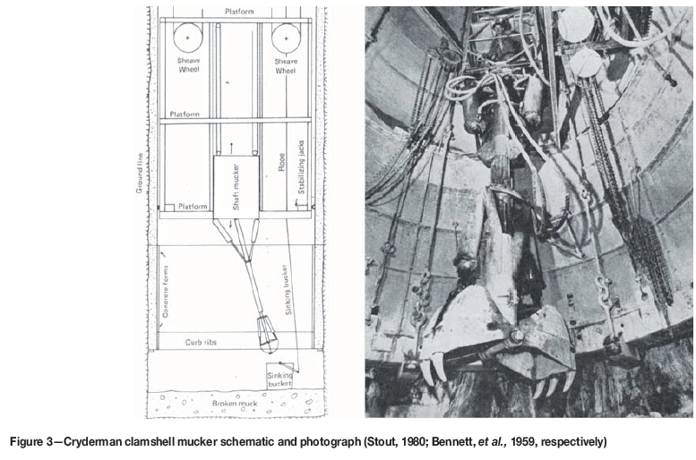
The EIMCO 630 loader is a tracked version of the model 12B loader. It consists of a frame mounted on tracks which may be independently controlled by air motors. It has a bucket at the front and a compressed air-operated mechanism to manipulate the bucket so that the material can be raised and discharged. The loader is driven forward so that its bucket penetrates the loose material ahead of it (also known as 'crowding'). The bucket is then raised and the loader is positioned so that the kibble is located directly behind it. The bucket is hoisted up over the loader and discharged into the kibble in an overthrow motion. Hence it is often referred to as an 'overshot loader' or an 'overthrow loader'. Figure 1 shows a schematic of the rail-mounted EIMCO 12B loader, illustrating the principle of loading and discharging. The operator is located on a running-board on the side of the loader so that he is able to move with the loader during the digging and discharging processes.
Specifications
► Dimensions with the bucket in the load position: 2.85 m length χ 1.75 m width χ 1.51 m height, with a bucket discharge height of 1.9 m for the 630 loader (Trident SA, 2016)
► Mass: 4.7 t (Trident SA, 2016)
► Bucket capacity: 0.27-0.39 m3 (ASME, 2000; Trident SA, 2016)
► Air supply: pressure of 520-860 kPa, at a flow rate of 18 m3/min (Trident SA, 2016).
Operational issues
As opposed to the rail-mounted model 12B, the individually controlled tracks of the model 630 enable the loader to turn sharply and have high degree of manoeuvrability (Berry, 1956). However, due to the 5 m2 footprint of the loader it is suitable for use in medium to large shafts, typically 5.5 m diameter and larger (Berry, 1956; Obert, 1973). It may, however, operate in smaller diameter shafts in the range 4.65.5 m provided it is used with a single kibble at the shaft bottom. In such cases, it is also necessary to use a special arm with a smaller nested bucket of 0.14 m3 capacity (Dengler, 1982). The consequence is that the loading rate will be reduced significantly.
Reported loading rates of the 630 loader vary. Berry (1956) stated that a 630 loader could load 15 to 18 cubic yards of solid material per hour (translating to about 39 t/h based on an assumed solid density of 2800 kg/m3). Jamieson and Pearse (1959) quoted a loading rate of 72 t/h for a shaft diameter of 7.6 m, while Dengler (1982) stated that loading rates may be as high as 90 t/h in sedimentary formations. In general, loading rates are dependent on the nature of the fragmentation, the size of the bucket and kibble, the available manoeuvring room, the skill of the operator, the operational state of the equipment, whether water is present at the shaft bottom, etc. An analysis and comparison of the loading rates is given in a subsequent section.
Owing to the size and mass of the unit, the 630 loader is not usually stored on the stage when it is not required (Jamieson and Pearse, 1959). Instead, it is lowered from surface at the start of the lashing part of the sinking cycle. While this facilitates maintenance on surface it does incur time penalties in lowering the loader down the shaft and through the shaft sinking stage. However, once the loader is at the shaft bottom, provided it is connected to an air supply, it can operate largely independently of the position of the shaft sinking stage. Aside from providing clearance for the loader to pass through it, the stage design is not significantly affected as the stage is not required to support the loader. In addition, the installation of shaft steelwork is not affected (Jamieson and Pearse, 1959).
When the loader's bucket is lowered and the unit is driven forward, blasted material is forced into the bucket due to the resistance of the muckpile, which limits the sliding of material fragments over one another. When the muckpile becomes shallow, towards the end of the cleaning cycle, the bucket filling efficiency is reduced substantially due to the shape and angle of the bucket and the lower resistance of the muckpile. This may result in lower fill factors and therefore lower efficiencies.
Dengler (1982) stated that this type of mucker is not suitable in the case of extremely coarse fragmentation or extremely abrasive muck. Britton and Lineberry (1992) stated that for all mechanical lashing, medium-sized fragmentation (approximately 125 mm) is most efficient. In general, fragments in excess of 125 mm will also lead to lower bucket fill factors for the 630 loader, and higher penetration forces will be required to load material into the bucket Singh et al., (2001). If fragmentation is poor and the muck contains large rocks, it will be difficult to scoop these with the bucket and the loader's tracks will also struggle to develop the required traction. Similarly, if large amounts of fines are present the loader may again struggle to develop traction, and small amounts of water could cause the fines to adhere to the bucket and not discharge into the kibble.
Conditions at the shaft bottom affect the ability of the 630 loader to muck efficiently. While small amounts of water are reportedly easily tolerated, if the amount of water becomes substantial then the 630 loader is unsuitable. In extremely wet conditions, mud and water may ingress into the pneumatic motors and controls, which could lead to damage. Also, the water itself poses a risk to the operator who stands on the loader (Obert, 1973). Secondly, the 630 loader requires a reasonably flat working surface. This is also a requirement for the position where the kibble is to be placed, for the purpose of stability and worker safety. If the muckpile is uneven after a blast then it is necessary to shape it before loading can start (requiring 10-15 minutes) (Berry,1956). In addition to an even working surface of the blasted material, the surface of the solid material should be as level as possible. It would be difficult for the loader to traverse an uneven surface to reach all of the remaining muck due to obstacles over which the loader may not be able to move, as well as traction problems, and because of safety concerns for
The discharge height of the loader limits the rim height of the kibble that can be used (Wakefield, 2009). For the 630 loader the maximum kibble rim height is 1.9 m. Hoisting a specific volume of material necessitates a specific kibble diameter, which, in turn affects the clearance holes in the shaft sinking stage through which the kibbles must pass. Hence, the volume of the kibble becomes constrained when the 630 loader is used. While this may not be a problem for larger diameter shafts, it could present difficulties for smaller diameter shafts where there is limited space to create the clearance holes in the stage, and limited space at the shaft bottom for the kibble.
The number of workers required to operate the loader at the shaft bottom is reported by Berry (1956) to be four: the loader operator, a hose-man to control the pneumatic hose lines, a helper to hook and unhook the kibble cables, and a signalman to the mine hoist. This represents a significant number of workers at the shaft bottom, the location of the highest danger.
Safety is a significant issue when using the 630 loader for additional reasons to those already mentioned. In most cases the loader is pneumatically driven. Pneumatic cylinders and winches have an inherent compliance or 'springiness' due to the compressibility of the air. This results in jerky and imprecise motion of moving parts, which can pose a risk to workers (Moss, 2011). In addition, the process of discharging the material into the kibble is forceful. Since the operator is located immediately adjacent to the bucket and actuating mechanism, he is exposed to increased risks in this regard. If the loader is not correctly positioned, the discharged material may not enter the kibble correctly and some material may impact, and rebound off, the side of the kibble. This may pose a risk to the operator or other workers nearby. This also applies to the loading of oversize rocks, which must be carefully raised and discharged. These risks are exacerbated in smaller diameter shafts. Loading in a 4.3 m diameter shaft was described by Berry (1956) as being 'hazardous' due to the small amount of space available for workers, the kibble, and the loader.
Clamshell-type muckers - Riddell and Cryderman muckers
Clamshell muckers are characterized by two opposed buckets. The key difference between this arrangement and the single bucket arrangement of the EIMCO 630 loader is that the loading of material occurs by enclosing and entraining a volume of material between the two buckets, rather than by the resistance of the material in the muck pile.
Background
The Riddell clamshell-type mucker was introduced in 1943 in Canada and was reportedly immediately successful. The Cryderman mucker was introduced into Canadian mining in the late 1940s and began to gain popularity in the 1950s. It is still reportedly the most popular mucker for Canadian shaft sinkers, and has largely replaced the Riddell muckers in Canada (Graham and Evans, 2008).
Description and operation
Both of these lashing machines have clamshell bucket configurations and are attached to either the underside of the stage, to a structure that can move independently of the stage, or to the shaft sidewall. In all cases the operator is located in a suspended compartment, rather than at the shaft bottom, for safety reasons (Wilson, 1976). The main difference between the two types of muckers is that the Riddell mucking machine utilizes ropes and winches to suspend and actuate the clamshell buckets, while the Cryderman utilizes cylinders to actuate the buckets and a telescoping arm on which the buckets are mounted (Stout, 1980). The consequence of this difference is very important: the Riddell mucker relies on gravity for the buckets to penetrate the muckpile in order to scoop material, while the Cryderman buckets are able to penetrate the confined material in the muckpile under the action of the cylinder in the telescoping arm. Figure 2 shows the Riddell and Cryderman mucking machines side by side, for a rectangular shaft configuration. The cable suspension of the Riddell mucker and the telescoping arm of the Cryderman mucker are evident.
Riddell muckers rely on a track system to move the buckets within the shaft and were originally successful in rectangular shafts (Bennet, Harrison, and Smith, 1959). In modern circular shafts, the reach of the buckets is not properly catered for by the track system and more than one mucker on parallel track systems is required, as well as workers at the shaft bottom to manipulate the buckets to reach the sidewalls and the kibbles. This poses a risk to the workers since the buckets require some velocity to penetrate the muck pile. It is also potentially problematic in that slack ropes can lead to a dangerous situation, as well as damage to the ropes. The rope system also presents a fouling hazard for the kibbles that are being lowered or hoisted at the shaft bottom (Berry, 1956). Bennet et al., (1959) stated that for square, circular, and inclined shafts the Cryderman mucker was in common use at the time.
Only the Cryderman mucking machine will be dealt with in detail below (but will be contrasted with the Riddell mucking machine, where relevant).
Specifications
All of the following specifications are for the Joy Global VSM 14 model (Joy Global, 2015) which is a modern version of the Cryderman loader.
► Dimensions: length 16.52 m (total length of unit including a base section which is located in a compartment in the stage such that the unit is able to move up and down relative to the stage), width 1.54 m, depth 0.96 m
► Mass: 8.6 t
► Bucket capacity: 0.38 m3 (standard capacity), 0.57 m3 (optional larger bucket capacity)
► 4.3 m main cylinder stroke on the telescoping arm (refer also to Moore, 2015)
► Power supply: earlier models utilized compressed air, while modern models utilize a hydraulic power pack located on the stage.
Operational issues
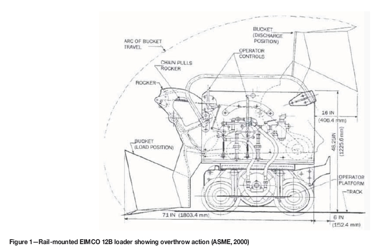
The Cryderman mucker may be attached to the underside of the stage, or it may be nested in the stage (see Figure 3) and lowered by an independent hoist at the commencement of lashing. This allows the unit to be retracted into the stage at the end of lashing so that there is clearance below the stage for drilling and concrete lining. In this retracted position, access for maintenance of the cylinders, hoses etc. is facilitated.
Although the 4.3 m stroke of the telescoping arm does accommodate the position of the Cryderman mucker relative to the bucket position and allows lashing of an area of the shaft bottom, it is necessary that the stage position be changed from time to time as the lashing progresses to accommodate the change in the level of the muck. The expansion ratio of blasted to solid rock may be in the range of 1.5-2, so a 3 m round will translate to 4.5-6 m depth of muck, which cannot be reached with an arm stroke of 4.3 m. The telescoping action of the arm allows the Cryderman mucker to scoop material in the muckpile and then retract so that the buckets may be positioned above the kibble and the material discharged. However, depending on the relative positions of the stage, muckpile, and kibble, this motion may be awkward. For example, if the stage is close to the muckpile, the telescoping arm may be near the limit of its retraction stroke and it may not be able to retract sufficiently to allow the buckets to be raised above the kibble rim, if the kibble is positioned too close to the mucker. This would necessitate that material be discharged into a kibble located further away, where the arm can be angled so that the buckets clear the rim.
Single Cryderman muckers are suitable for use in shaft diameters less than about 5.5 m, but for shafts larger than 5.5 m it is common practice to use two muckers (Dengler, 1982). There are two reasons for this: the muckers are not mounted centrally so the extents of larger diameter shafts cannot be reached from one location only; and the loading rate for a single Cryderman mucker is lower than that of the 630 loader. Data for earlier versions of Cryderman muckers indicated loading rates of up to 50 t/h Dengler et al., (1992), while a more modern hydraulic version was reported by Dengler (1982) to have an expected loading rate of 73 t/h (with the larger bucket volume of 0.57 m3). Berry (1956) felt that a clamshell loader of the time could probably load up to 15 cubic yards of solid material per hour (or 32 t/h at an assumed solid density of 2800 kg/m3). There is currently no published data on the loading rate of the newer Joy Global VSM 14 unit, but personal communication between the author and a local contractor indicate that the unit is rated at about 60 t/h.
The Cryderman mucker is powered by either pneumatic or hydraulic cylinders (for lateral positioning of the arm, telescoping of the arm, and closing of the buckets). Pneumatic cylinders will have a significant degree of compliance due to the compressibility of the air which, together with the nature of pneumatic controls, will lead to imprecise movements of the arm and buckets. In contrast, hydraulic cylinders will be stiff and will therefore result in more accurate positional control of the buckets. Since the buckets in the Cryderman mucker are not supported on cables this type of mucker can be used in inclined shafts (Dengler, 1982). Hydraulic versions require an additional power pack to be located on the stage, while pneumatic units use the installed compressed air on the stage.
The ability of the buckets of a Cryderman mucker to penetrate the muckpile under the action of a cylinder is of critical importance in that it leads to potentially higher bucket fill factors than with the 630 loader or any form of muck penetration under the action of gravity alone. Since the buckets are not suspended on ropes, workers at the shaft bottom are not exposed to swaying or uncontrolled motion of the buckets. There are also no ropes that can become slack, or which could become entangled with kibble hoist ropes.
Bucket shape has evolved over time. The original Cryderman clamshell buckets were rounded on the underside. In some versions, such as that shown in Figure 3, the jaw edges are flat (known as the 'Brutus' buckets), while the modern Joy Global unit again has rounded edges. Some benefit may be obtained when using the rounded shape to muck against the sidewall as the angle of the arm to the vertical will result in the bucket being angled to the sidewall, and the bucket may scoop more material if it is rounded. In laboratory experiments conducted by Moss (2011) using a 1:6 scale model of a clamshell digger (based on a Cryderman mucker) it was shown that lashing against a sidewall was easily achieved for the case where the sides of the buckets were parallel to the sidewall) and did not adversely affect the digging forces. The ability to muck against a sidewall is an advantage of this type of mucker. It is unclear from the literature whether the buckets are able to rotate on the telescoping arm so that their sides may be oriented parallel to the shaft sidewall. If this is not the case then lashing against the sidewall will not always be efficient, depending on where the unit is lashing relative to its support location.
In addition to bucket shape, the bucket size should be also chosen in relation to the kibble diameter. Since the arm of the Cryderman mucker will be at an angle relative to the kibble for most of the lashing operations, its clamshell buckets will also be at an angle to the vertical and need to open sufficiently to be able to discharge the muck into the kibble. If the clamshell buckets are too large there may be insufficient room to open them completely, and they may not discharge the material completely into the kibble. The result could be spillage or carry-back of material remaining in the buckets, which would reduce the effectiveness of the loading.
Berry (1956) stated that the fragmentation of the rock was less of an issue with the Cryderman mucker than with the 630 loader, provided the rocks were not so large that they did not fit into the clamshell buckets. Large rocks would be problematic with Cryderman muckers. One additional consideration is that if the blasted material has a wide particle size distribution a large rock fragment could prevent the buckets from closing properly, leaving gaps between the jaws through which smaller particles may escape. This would lead to lower bucket fill factors and potentially less efficient loading.
Conditions at the shaft bottom also have an effect on the efficiency of the Cryderman mucker. Water in reasonable quantities is not considered a problem for the Cryderman mucker (as compared with the 630 loader) as the controls are not located anywhere near the water. Safety for the operator is improved, as he is located well away from the shaft bottom (Wilson, 1976), although if workers are required to detach and attach kibbles to the hoist ropes, they would be exposed to risk. Visibility for the operator is improved as he is located above the operations so there are fewer blind spots. Cryderman muckers are also not affected significantly by an uneven material surface after the blast, provided the kibbles can be located such that they are stable. They are also able to muck effectively if the surface of the solid material is uneven, provided they have sufficient reach.
Safety is generally improved when Cryderman muckers are employed for the reasons outlined above. However, while visibility of the working area may be improved with the operator located above the shaft bottom, communication with workers below is more difficult. If a second mucker is used the working area does become congested, and there are increased risks for workers in the vicinity.
No mention is made in the literature of how the remnants of the blasted rock are loaded into the kibble when Cryderman muckers are used for lashing, but presumably material is hand-lashed into the closed clamshell buckets and then loaded into the kibble. The location of the actuating cylinders on the outsides of the buckets may be problematic in this regard, as they could be prone to damage. In addition, the shape of the bottom surface of the bucket (flat versus round) may affect the cleaning ability when the layer of muck becomes shallow.
Cactus grab
The cactus grab was introduced In the 1950s, and was used successfully in 1952 during the sinking of No. 2 shaft at the Vlakfontein mine in South Africa (Graham and Evans, 2008). The cactus grab has seen continuous use since its introduction and is globally a popular choice for lashing as it has a high loading rate.
Description and operation
The cactus grab consists of a 6- or 8-tine (or claw) grapple that is activated by a large pneumatic cylinder, and which is suspended from a cable hoist system. The cables are attached to an arm which is pivoted centrally on the shaft sinking
stage such that the arm can sweep through 360 degrees. The hoist for the grab can move radially along the arm such that the grab can cover all areas of the shaft bottom. Figure 4 shows a schematic of the cactus grab, cable hoisting system, cantilevered arm, kibbles, and operator's compartment.
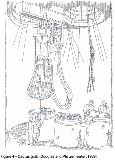
The loading action is as follows. The grab is lowered into the muckpile with the tines open. Then the pneumatic cylinder actuates the tines so that they close and entrain a volume of muck. The grab is then raised, positioned over a kibble, and the tines opened so that the load of rock is discharged into the kibble.
Specifications
► Dimensions: grab height 3.2-3.7 m, grab diameter (open) 2.2-2.8 m, (closed) 1.7-1.8 m (Deilmann-Haniel, 2014)
► Mass: 10 t (Martin and Harvey, 1989)
► Shaft diameter range: 7-11 m (Deilmann-Haniel, 2014)
► Grab capacity (volume): 0.4-0.85 m3 (Dengler, 1982); 0.5-1.2 m3 (Deilmann-Haniel, 2014), with typical grabs either 20 ft3 (0.56 m3) or 30 ft3 (0.85 m3)
► Power supply: compressed air at 400-600 kPa with a consumption of between 120-140 m3/min, depending on grab size.
Operational issues
The cactus grab unit is mounted to the underside of the shaft sinking stage. This is seen as a significant disadvantage as heavier stage steelwork is required to support it. This, in turn, necessitates larger stage hoist ropes etc., which all add cost to the project. A further disadvantage is the space that the cactus grab occupies underneath the stage. This limits the distance that the stage can be lowered and so the shaft concrete lining may not come as close to the shaft bottom as is desirable. According to Martin and Harvey (1989) this, as well as the particular geology, was the reason that the cactus grab was not chosen as the lashing system for the sinking of the Asfordby shafts. An advantage of the cactus grab system, though, is that provided its hoist ropes are long enough it may operate reasonably independently of the stage position.
Cactus grabs are suited to larger diameter shafts. Obert (1973) stated that cactus grabs may operate in shafts less than 6.7 m diameter, but they are economically suited to larger diameter shafts. He further stated that for shafts larger than 9.8 m diameter the cactus grab is the only economically viable option.
The loading rates published in the literature vary. Dengler et al., (1992) stated that typical loading rates may be in excess of 100 t/h, Wakefield (2009) stated that 180 t/h is possible, while according to MacGillivray (1979) peak loading rates up to 250 t/h are possible with a large capacity grab (0.85 m3). MacGillivray (1979) further noted that 'A lashing unit with a pneumatic cactus grab is unequivocally the fastest shaft mucker in vertical shafts and is universally adopted for rapid sinking in large deep shafts'. Despite the high instantaneous loading rates that are quoted by MacGillivray and Wakefield, the data presented by Morgan (2015) indicates that the average loading rate was about 50 t/h, excluding blow-over, on the basis of an 8.1 m diameter shaft, 3.15 m advance per blast, estimated solid rock density of 2800 kg/m3, and lashing duration of 9 hours. In reality, instantaneous rates should be significantly higher, but Morgan's figures would be comparable to other types of loaders.
In a similar manner to the Riddell mucker, the cactus grab relies on gravity for the tines to penetrate the muckpile. This has the consequences of uncontrolled motion during the scooping action, potentially shallow penetration, slackening of the grab's hoist rope, and potential fouling of the grab ropes with the kibble ropes. Due to the shape of the grab and tines, it cannot clear material effectively against the shaft sidewalls because of the distance between the tines when they are open, and the shape of the grab when the tines are closed. In addition, the cactus grab is not effective towards the end of the cleaning cycle when the layer of muck becomes shallow and the tines make contact with solid material. MacGillivray (1979) indicated that the amount of material removed in the blow-over phase (when the grab has become ineffective) was as much as 60 t for larger shaft diameters, about 10 t of which had to be hand-lashed as the cactus grab was ineffective in clearing this material. Morgan (2015) indicated that the depth of loose material at which the grab became ineffective was about 200 mm, by which stage the large fragments had already been loaded, and smaller fragments were escaping through the gaps between the tines. Using the same data as quoted by Morgan above, and assuming an expansion ratio of two for the blasted material, this layer of muck amounts to approximately 14 t, which is in reasonable agreement with MacGillivray. Hand lashing is done by placing the material into the closed grab through the gaps between the top of the tines, and then using the grab to deposit the material into the kibble (Douglas and Pfutzenreuter, 1989).
Large rocks are more easily handled with a cactus grab than with other types of loaders (Dengler, 1982); however, fine fragments are more difficult to handle, particularly when the tines are worn. Britton and Lineberry stated that typically 70-80% of the muck produced in a blast has fine fragmentation with the rest being coarse. The combined effects of fines and worn tines will therefore lead to lower loading rates.
Conditions at the shaft bottom do not affect the cactus grab significantly. It is able to operate if the blasted material surface is uneven, provided the kibbles are stable, and is also able to operate if water is present.
Due to the location of the cactus grab on the underside of the stage, maintenance is an issue. MacConachie (1959) stated that typically four units were utilized in a sinking operation: one operating, one spare, one undergoing minor repairs, and one undergoing major overhaul. He also stated that repairs were generally not carried out in situ (unless of a minor nature), but that the damaged unit was rather replaced and brought to the surface for repairs. The size, complexity, location, and mass of the components in a cactus grab system make this task difficult. Care must also be taken with regard to the grab hoist ropes. In the analysis that Morgan (2015) conducted for 152 sinking cycles, of the 429.8 hours of engineering-related delays (out of 4440.5 actual hours worked) the cactus grab accounted for almost 122 hours of delays (or 28% of the engineering delays). In particular, 59 hours of delays associated with the cactus grab were associated with ropes.
When using a cactus grab, safety is a serious issue. The size and mass of the grab, the use of a rope support system for the grab, and the need for the grab to penetrate the muckpile under the action of gravity all make it dangerous to operate with workers in the vicinity. While the operator does have good visibility, depending on the location of the stage while lashing is in progress (which is considered an advantage of this system), the operator may be located quite far from the shaft bottom. This makes communication more difficult, and reduces the controllability of the grab even further. There is also the need to ensure that kibble hoist ropes do not become entangled with the grab.
Other types ofmucking systems
The main lashing techniques that are currently employed worldwide have been covered above. However, there are other techniques, although these will not be explored in as much detail. These include excavators, roadheaders, and shaft borers.
Roadheaders such as the Herrenknecht shaft boring roadheader (Herrenknecht, 2016) can reportedly be used in shaft sinking applications for 8-12 m diameter shafts, sunk to a depth of 1000 m, where the application is in 'soft to medium-hard rock'. However, no details of rock strength, hardness, abrasivity etc. were supplied. The roadheader uses a pneumatic system to hoist the rock fragments from the cutting process.
Shaft borers such as the Herrenknecht shaft boring machine (Herrenknecht, 2016) can reportedly be used in shaft sinking applications for 10-12 m diameter shafts, sunk to a depth of 2000 m. The unit uses vertical conveyors to hoist the muck.
Excavators have also been used in lashing operations in shaft sinking. Dengler (1982) mentions an Alimak mucker which is based on a single bucket mounted on an articulating arm (in the same configuration as a backhoe). The arm may be attached to the underside of the stage or onto a structure temporarily attached to the sidewall. There are other excavators employing similar action using a single bucket, such as the Terex S20 excavator, which is mounted on the underside of the shaft sinking stage.
Lastly, track-mounted excavators have also been used. Morgan (2015) gave some data on cycle times and experience gained used an excavator, and also made some predictions of lashing cycle times. In the data presented, a Hyundai R60-9S 5.6 t excavator with a 0.31 m3 bucket capacity was used in a sinking application. An average digging cycle time of 13 seconds was recorded (although this was measured for only five complete digging cycles incorporating a swing angle of 90 degrees). It is not clear whether these cycle times were achieved in an actual lashing context. Morgan (2015) also described the use of another track-mounted excavator (a Hyundai R55-7 5 t unit) which was used in the sinking of a 9 m diameter shaft. It had advantages of increased mobility, was able to be operated independent of stage location, and it allowed blow-over material to be blown directly into the bucket. No data for this application was presented. The main issues that were experienced were the need to hoist the excavator from surface before lashing could begin (and to remove the driver's cabin and excavator arm), having openings in the stage that could accommodate the excavator, and failures in the hydraulic and electrical systems. The author would add efficiency of bucket filling, due to the need for resistance in the muckpile, to the disadvantages. Morgan proposed that it would be possible to allow the kibble ropes to remain attached during loading, and indicated that the excavator could be adapted for remote control, which would remove people from the shaft bottom and also do away with the operator's cabin.
Analysis oflashing rates
In order to assess the lashing rates of the various types of lashing machines, the following equation was derived:
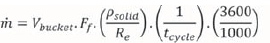
where m = mucking rate (t/h )
Vbucket = bucket geometric volume (m3)
Ff- - bucket fill factor (dimensionless)
Psolid = density of solid rock
Re - expansion ratio of blasted rock (dimensionless)
tcycle = mucker digging cycle time (seconds)
Conversion constant: kg to tonnes, and seconds to hours

Note that this equation does not take into account the time taken to detach and re-attach kibbles, varying bucket fill factors as the muckpile becomes shallow, operator fatigue and reduced efficiency, or the effect that any other activity not related to lashing will have on the lashing rate. In reality, these factors could reduce the instantaneous lashing rate substantially.
For the purposes of comparison, the following parameters will be used:
► Bucket size from 0.18-0.50 m3 for an excavator, 0.270.39 m3 for an EIMCO 630 loader, 0.27-0.57 m3 for a Cryderman loader, and 0.57-1.20 m3 for a cactus grab
►Bucket fill factor approximately 0.65
► Expansion ratio from solid to broken rock approximately 2
► Density of solid rock 2800 kg/m3
► Advance per blast 3 m, with shaft diameters varying from 6-12 m
► Only one mucker operational
► Instantaneous digging cycle times vary linearly as a function of bucket volume, from 15 seconds for a 0.18 m3 bucket to 35 seconds for a 1.2 m3 grab. Efficiencies that may relate to both bucket fill factors as well as increased cycle times have been included in the analysis, ranging from 50% to 100%. The assumed cycle times do not take into account inherent differences in the lashing techniques.
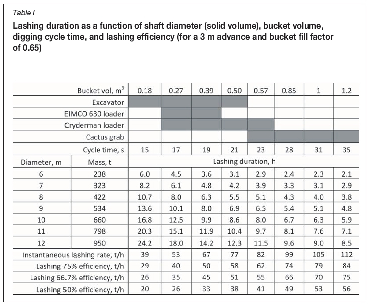
The results are shown in Table I. At the top of the table, various bucket volumes are indicated, as well as the typical bucket sizes associated with various lashing techniques. The cycle times have been scaled linearly between 15 and 35 seconds based solely on bucket volume. Morgan (2015) indicated cycle times for an excavator of 13 seconds while Kratz and Martens (2015) assumed cycle times of 25 seconds for a Cryderman loader. No information on cycle times for a cactus grab were obtained from the literature.
In the lower portion of the table the masses of solid material associated with shaft diameters ranging from 6-12 m have been determined (based on a solid density of 2800 kg/m3), as well as the duration of the lashing cycle based on the bucket volume and cycle times. At the bottom of the table the instantaneous lashing rates are determined, and compared with reduced efficiencies, which may account for time taken to detach and re-attach kibbles, poor fragmentation, lower efficiencies towards end of lashing cycle in shallow material, etc. The latter may be considered to be more in line with average lashing rates.
The lashing rates quoted in the literature and those estimated in Table I compare as follows:
► EIMCO 630 loader: quoted rates varied between 39-72 t/h, which compare favourably with the estimates in the table, which range from 40-67 t/h for efficiencies of 75% and higher. The figure of 90 t/h quoted by Dengler (1982) in sedimentary formations may be indicative of better fragmentation, better bucket fill factor, and hence increased performance.
► Cryderman loader: quoted rates varied between 32-73 t/h, which also compare favourably with the estimates in the table, which range from 35-82 t/h, albeit with lower efficiencies at the lower end of the range. Presumably, the rate of 32 t/h quoted by Berry (1956) was at a reduced efficiency for operational reasons.
► Cactus grab: quoted rates varied between 100-180 t/h. MacGillivray (1979) estimated that rates may be as high as 250 t/h, and Wakefield (2009) indicated that loading rates of 180 t/h are possible, while estimated rates vary between 62-112 t/h for efficiencies above 75%. The data in Morgan (2015) showed that average loading rates were considerably lower at about 50 t/h, which is consistent with an efficiency between 50 and 66.7%, using a 0.57 m3 grab.
► Excavators: the only available data is given in Morgan (2015), which indicates cycle times of 13 seconds using a 0.31 m3 bucket. The estimated loading rates for excavators vary between 29-77 t/h for the range of bucket sizes. Using Morgan's cycle time of 13 seconds and a bucket volume of 0.31 m3, the mucking rate would be approximately 59 t/h (assuming a 75% efficiency). It is the author's view that the 13-second cycle time is probably slightly optimistic, as the data presented by Morgan was for a 90 degree swing only.
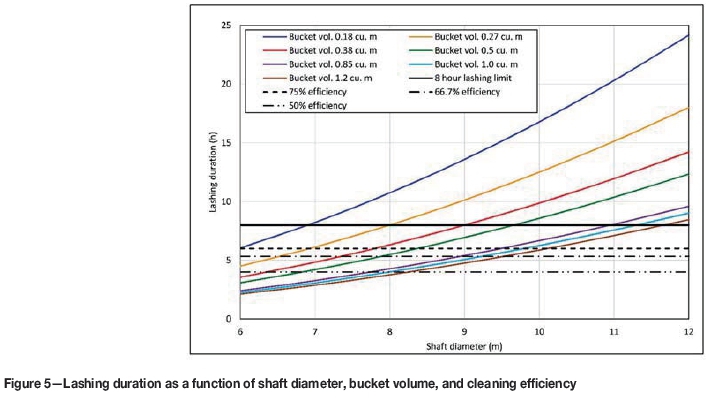
A graph of the lashing durations given in Table I is presented in Figure 5. The data is extrapolated to assess how long it would take to muck the volume of material generated for the different shaft diameters (with the same assumptions of 3 m advance, bucket fill factor of 0.65, solid density of 2800 kg/m3, expansion ratio of 2, and digging cycle times linearly related to bucket volume). The figure shows, for example, that the theoretical lashing duration for an 8 m diameter shaft would be 8 hours if a bucket volume of 0.27 m3 was used and the lashing operated at 100% efficiency.
The lashing duration is compared with an 8-hour shift time, and an efficiencies of 100%, 75%, 66.7%, and 50% are applied to assess how operational efficiencies could affect the lashing duration (for example lowering of the mucker from surface, or detaching and re-attaching ropes to kibbles, etc.). The figure shows that larger bucket volumes are required for larger shaft diameters if the lashing durations are to be below 8 hours. For example, a bucket volume of at least 0.5 m3 should be used when an 8 m diameter shaft is being sunk (if the system has an efficiency of approximately 66.7%). Care should be taken, though, in using this information because an average bucket fill factor of 0.65 was used and larger
buckets are likely to suffer from significantly reduced fill factors towards the end of the lashing cycle due to the shallow layer of muck remaining.
Summary and recommendations
There are numerous advantages and disadvantages for all of the shaft lashing techniques reviewed in this paper. Since the lashing cycle time is dictated by the rate at which material is lashed (rather than the time taken to hoist and lower kibbles), and since lashing occupies a significant portion of the overall cycle time, it is clear that the loading rate is the primary criterion by which the lashing system is selected. There are, however, additional factors to be considered which relate either to the system as a whole or to the front end of the system where the actual lashing takes place. These include:
► The shaft diameter and number of lashing units required
► The mass of the lashing equipment
► Whether the lashing system is supported on the stage or not
► The cost of the equipment (capital and operational)
► The location where the lashing equipment is stored when not in use and whether this affects other stage functions and sinking operations
► Constraints and risks that the lashing system imposes on the kibble hoisting system and stage design
► Whether the stage is required to be moved to accommodate the changing level of the muck
► Whether the muck surface after a blast and the surface of the solid material below the blasted material are level or not
► The ability of the lashing system to load material against the sidewall
► The ability to lash when the layer of muck becomes shallow
► How much material is required to be moved and hand-lashed during blow-over
► Worker safety during shaft bottom operations and the number of workers required to operate a specific system
► Communication between workers and operators
► Whether water is present at the shaft bottom and in what quantity
► Maintenance of lashing equipment
► Energy source
► The drilling pattern and type of explosives used, and the resulting fragmentation.
The EIMCO 630 loader and the Riddell clamshell mucking system were shown to have significant disadvantages, primarily related to safety of operations and suitability to particular shaft configurations, the fragmentation size, and condition of the blasted material. Consequently, they are not commonly used any longer.
The Cryderman mucking system has been shown to address some of the issues of the Riddell mucking system. In particular, the telescoping arm increases the safety of workers at the shaft bottom by providing accurate control of the positioning of the clamshell buckets. It was also shown that it has a better ability to clean material against the sidewall. The main concerns with the Cryderman mucking system are the loading rate and dealing with oversize rock fragments. In certain shaft sinking operations it was shown that two Cryderman loaders could be used simultaneously to increase the loading rate provided the shaft diameter was large enough. While this would increase the cost and complexity of lashing operations, and would reduce safety levels for workers at the shaft bottom somewhat, it does, however, also introduce a measure of redundancy should one of the units fail in service.
It is clear from the literature that the cactus grab has the highest instantaneous loading rate, but it is not clear whether the average loading rates are significantly lower due to the need to hand-lash a large amount of material at the end of the lashing cycle, due to the inefficiency of the grab when the layer of muck is shallow. There are numerous other disadvantages of the cactus grab. In particular, a few aspects that are of concern are the weight of the unit (which affects the stage design), the significant amount of space that it occupies underneath the stage (which inhibits other cycle functions), its reliance on gravity in order for the tines to penetrate the muckpile, its inability to clean effectively against the sidewall or when there is a shallow layer of material or the material contains a large proportion of fines, its uncontrolled and therefore unsafe movements as a result of the rope suspension system, and difficulty in conducting maintenance in situ.
Excavators appear to be promising but there is little published data available. Since they have one bucket they rely on the resistance of the muckpile to force material into the bucket, which is a disadvantage. Storage of the excavator on surface is also problematic as the transport time and stage requirements to allow it through are onerous.
An analysis of lashing duration as a function of shaft diameter and digging cycle times was conducted for an assumed advance of 3 m per blast, bucket fill factor of 0.65, solid rock density of 2800 kg/m3, and expansion ratio of 2. The predicted lashing durations compared favourably with current lashing techniques.
Taking into account the advantages and disadvantages of the various lashing systems described so far, and without consideration of other functions of the shaft sinking cycle, the ideal lashing system should:
► Have opposed buckets to entrain muck without relying on the resistance of the muckpile
► Be able to clean against the sidewall as well as scoop muck effectively in a shallow layer
► Have a bucket volume of at least 0.5 m3 and be able to scoop reasonably large fragments
► Either be located at the shaft bottom so as to work independently of the stage location (which would require either storage on the underside of the stage, or ability to pass through the stage to be stored on the surface), or be integrated into the stage but have independent motion so as to be able to muck with minimal movement of the stage
► Be flexible enough to cope with varying height differences between the location of the buckets, the relative location of the top rim of the kibble, and the surface of the muckpile
► Be able to muck shafts with diameters in the range of 6-12 m with reasonable scalability (i.e. duplication to two muckers in larger diameter shafts)
► Have lateral and vertical positional control by means of cylinders (including penetration of the muckpile) in order to improve safety and bucket fill factors
► Be tolerant of water and uneven surfaces at the shaft bottom
► Improve safety in the shaft bottom by having a smooth, well-controlled motion, by limiting the number of workers required at the shaft bottom, by not occupying a large amount of space (which could be dangerous in small diameter shafts where space is limited)
► Have a mass as low as possible if it is to be attached to, or slung from, the stage
► Be maintainable on the stage or at the shaft bottom.
Of the lashing methods assessed in this review, the Joy version of the Cryderman mucker is the only one with an opposed bucket configuration and direct cylinder action to penetrate the muckpile. It does have constraints as far as cylinder stroke and positioning relative to the shaft bottom are concerned, particularly when operating in larger diameter shafts. There is the potential to introduce an additional degree of freedom such as a knee joint, which would give it more flexibility, but at the cost of increased complexity and mass. In addition, there is scope to address the bucket action for the case of a shallow layer of muck. Ideally, a deep penetrating bucket action would be better when the layer of muck is deep, while a shallow, gathering action would be beneficial when the layer is shallow.
References
AngloGold Ashanti. 2017. South Africa. http://www.anglogoldashanti.com/southern-africa/ [accessed 16 February 2018] [ Links ]
ASME Engineering History Landmarks. 2000. The EIMCO Rocker Shovel Loader Model 12B. ASME International, Miner's Plaza, Park City, Utah. https://www.asme.org/about-asme/who-we-are/engineering-history/landmarks/212-eimco-rocker-shovel-loader-model-12b [accessed 19 February 2017]. [ Links ]
Bennett, W.E., Harrison, P., and Smith, G.E. 1959. Shaft sinking in Canada. Proceedings of the Symposium on Shaft Sinking and Tunnelling, July 1959. Institution of Mining Engineers, London. pp. 238-252. [ Links ]
Berry, T.M. 1956. Shaft loading: clamshell vs crawler-mounted loader. Proceedings of the Loading and Transportation Symposium. Mining Engineering, vol. 8, no. 12. pp. 1196-1198. [ Links ]
Britton, S.G. and Lineberry, G.T. 1992. SME Mining Engineering Handbook. 2nd edn, vol. 2. Hartman, H.K. (ed.). Society for Mining, Metallurgy, and Exploration, Inc., Littleton, CO, USA. Section 17, pp. 1543-1678. [ Links ]
Brunton, I., Thornton, D., Hodson, R., and Sproutt, D. 2003. Impact of blast fragmentation on hydraulic excavator dig time. Proceedings of the 5th Large Open Pit Conference, Kalgoorlie, WA, 3-5 November 2003. [ Links ]
Workman-Davis, C. and Chanda, E. (eds). Australasian Institute if Mining and Metallurgy, Melbourne. pp. 39-48. [ Links ]
CATERPILLAR. 1998. Caterpillar Performance Handbook, Edition 29. Caterpillar Inc., Peoria, IL, USA. pp. 4-120. [ Links ]
Engineering News. 1999. World's deepest single-lift shaft project. http://www.engineeringnews.co.za/article/worldx2019s-deepest-singlelift-shaft-project-1999-11-26 [Accessed 16 February 2018]. [ Links ]
Deilmann-Haniel Mining Systems. 2014. Grab systems technical data. http://www.dhms.com/en/products/shaft-hoisting-shaft-sinking-equipm/grab-systems-dh-dg.html [accessed 12 April 2017]. [ Links ]
Dengler, W.R. 1982. Shaft machines. Underground Mining Methods Handbook. Society of Mining Engineers of the American Institute of Mining Engineering. Chapter 10, pp. 1263-1266. [ Links ]
Dengler, W.R., Shaver, W.M. and Letourneau, R. 1992. New technology in shaft sinking - the Craig Project. Proceedings of the SME Annual Meeting, Phoenix, AZ, 24-27 February 1992. Society for Mining, Metallurgy and Exploration, Inc., Littleton, CO. [ Links ]
Douglas, A.A.B. and Pfutzenreuter, F.R.B. 1989. Overview of current South African vertical circular shaft construction practice, Proceedings of Shaft Engineering, March 1989, Institution of Mining and Metallurgy, London, UK. pp. 137-154. [ Links ]
Graham, C., and Evans, V. 2008. History of Mining - The evolution of shaft sinking systems (Part 5), Shaft sinking from 1940 - 1970: The golden age. CIM Magazine, March/April 2008. [ Links ]
Herrenknecht Technology. 2016. Mining - Safe and fast development of underground mines. Product brochure 2382. https://www.herrenknecht.com/en/applications/mining.html [accessed 4 October 2017]. [ Links ]
Internet Archive, 1992. EIMCO, Pioneer in Underground Mining Machinery and Process Equipment, 1926-1963: Oral History Transcript, pp.49-67. https://archive.org/details/pioneerunderground00roserich [accessed 28 February 2017]. [ Links ]
Jamieson, D.M., and Pearse, M.P., 1959. Shaft planning for mines in the new Consolidated Gold Fields Group. Proceedings of the Symposium on Shaft Sinking and Tunnelling, July 1959. . Institution of Mining Engineers, London. pp. 318-331. [ Links ]
Joy Global. 2015. Shaft sinking equipment product overview. Joy Global, Milwaukee, WI. [ Links ]
Kratz, T., and Martens, P.N. 2015. Optimization of mucking and hoisting operation in conventional shaft sinking. Mining Report , vol. 151, no 1. pp. 38-47. [ Links ]
MacConachie, H. 1959. Shaft sinking practice in South Africa. Proceedings of the Symposium on Shaft Sinking and Tunnelling, July 1959. Institution of Mining Engineers, London. pp. 3-28. [ Links ]
Murray and Roberts. 2017. Underground mining. http://wwww.murrob.com/capunder-mining.asp [accessed 16 February 2018]. [ Links ]
MacGillivray, D.M.,1979. High speed shaft sinking techniques in South Africa. Proceedings of the Rapid Excavation and Tunnelling Conference, Atlanta, GA, 18-21 June 1979. Vol. 2. Maevis, A.C. and Hustrulid, W.A. (eds). Society of Mining Engineers, New York. [ Links ]
Martin, C.J.H. and Harvey, S. 1989. Sinking of the Asfordby Mine shafts. Shaft Engineering. Institution of Mining and Metallurgy, London, UK pp. 289-296. [ Links ]
Moore, E. 2015. Building a better shaft mucker. CIM Magazine, October 2015. [ Links ]
Morgan, G. 2015. Investigation into current shaft sinking processes with a view to proposing improvements in work practices with regard to productivity and safety. MEng investigational project report, University of the Witwatersrand, Johannesburg, South Africa. [ Links ]
Moss, S.T., 2011. Development of a scale model clamshell mucker and validation by discrete element modelling. MSc thesis. University of the Witwatersrand, Johannesburg, South Africa. [ Links ]
Obert, L. 1973. Opening and development. Mining Engineering Handbook. Society of Mining Engineers (SME), New York. Volume 1, section 10. pp. 10.2-10.104. [ Links ]
Singh, S., Glogger, M. and Willock, D., 2001. Effect of fragmentation on loader efficiency. In Proceedings of the Annual Conference on Explosives and Blasting Technique. Vol. 2. ISEE, New York. pp. 77-88. [ Links ]
Stout, K.S. 1980. Mining Methods and Equipment. McGraw-Hill, New York, USA. pp. 68-69, 98-103. [ Links ]
Trident SA. 2016. 630 Rockershovel. http://www.tridentsa.co.za./630.html [accessed 28 February. 2017]. [ Links ]
Wakefield, T. 2009. Approaches to improve safety and recover lost productivities in vertical shaft sinking by making use of industrial engineering and risk driven 3-D modelling techniques. Proceedings of the Shaft Sinking and Mining Contractors Conference 2009, Johannesburg, South Africa. Southern African Institute of Mining and Metallurgy, Johannesburg. [ Links ]
Wilson , J.W. 1976. Shaft sinking technology and the future needs of the mining industry. Proceedings of the 1976 Rapid Excavation and Tunneling Conference, Las Vegas, NV, 14-17 June 1976. Robbins, R.J. and Conlon, R.J. (eds.) Society of Mining Engineers, New York. pp. 103-125. [ Links ]
Paper received Mar. 2017
Revised paper received Feb. 2018

