


Servicios Personalizados
Articulo
 Inglés (pdf)
 Articulo en XML
 Referencias del artículo
Indicadores

Links relacionados
-
 Citado por Google
 -
 Similares en Google
Compartir

 Permalink
Journal of the Southern African Institute of Mining and Metallurgy
versión On-line ISSN 2411-9717
versión impresa ISSN 2225-6253
J. S. Afr. Inst. Min. Metall. vol.118 no.3 Johannesburg mar. 2018
http://dx.doi.org/10.17159/2411-9717/2018/v118n3a11
PAPERS OF GENERAL INTEREST
Trials of the Garford hybrid dynamic bolt reinforcement system at a deep-level gold mine in South Africa
F. Sengani
South Deep Goldfields Mine, South Africa
SYNOPSIS
Efficient dynamic bolt reinforcement is crucial in deep-level gold mines prone to rockbursts. Deep-level gold mining in South Africa is approaching 4000 m, so appropriate support designs need to be implemented to manage ground stability challenges associated with these great depths. In order to extract the orebody, both novel mining methods and massive mining techniques have to be applied. Currently, massive mining techniques are used and destressing is imperative. Destressing is accomplished by cutting a series of overlapping, 5 m high horizontal slots across the reef. Although the minor span of each slot is about 100 m, stresses are extremely high due to presence of abutments. In order to protect workers from the effects of small seismic events, a yielding support system consisting of weld mesh (100 mm apertures and 5 mm strands) and 2.5 m long Garford hybrid bolts has been developed. The support system allows installation to be made at 0.5 m from the advancing face without significant damage by the blast. A tendon pretension of 49.3 kN ensures an active support system at installation, with 29 kJ/m2 energy absorption capacity during seismic events, and static tensile capacity of 147 kN. The effectiveness of the Garford hybrid bolt is discussed in this paper.
Keywords: ground support, yielding support, dynamic bolt, Garford bolt.
Introduction
As mining progresses from deep to ultra-deep levels, stress levels increase rapidly. This compromises the effectiveness of support systems and the stability of excavations underground (Ortlepp, 1992). Excavations driven into highly stressed ground typically suffer from stress-induced damage (Mühlhaus, 1990; McCreath and Kaiser, 1992; Maxwell, and Young, 1997; Daehnke et al., 1998). Stress-induced damage can result from either the creation of new fractures or the reactivation of existing fractures in the rock mass (Brady and Brown 1993). As a result of these challenges, rock support systems for underground excavations have changed significantly due to improved technologies and experience gained (Ortlepp, 1992; Jager and Ryder, 1999)
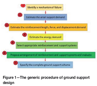
Ground support/reinforcement design
Ground support/reinforcement design has evolved into a comparatively complex discipline involving the quantification of various rock mass and support parameters (Villaescusa, and Wright, 1997, 1999). A flow chart indicating the principal design steps that should be followed when designing support systems specific to a given geotechnical environment is shown in Figure 1. The generic procedure consists of several distinct steps. In many instances, there may be nothing technically wrong with the design and the performance can be considered acceptable. However, rock mass conditions usually change with the progress of a mine (e.g., stresses increase as depth of mining increases and when the extraction increases) and accordingly, the performance of the ground support may change and become unacceptable (Brady and Brown 1993; Villaescusa, and Wright, 1997, 1999; Jager and Ryder, 1999).
Destress technique
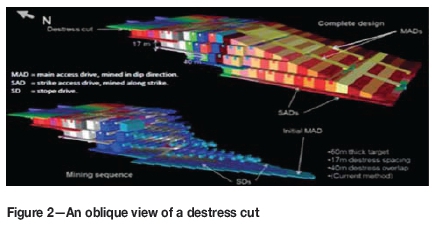
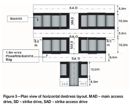
A deep-level gold mine is currently mining at a depth of about 2600 m below surface, with a horizontal-to-vertical stress ratio of about 0.7. Virgin stresses are high in deep to ultra-deep mines, which makes it difficult to implement massive mining techniques. Hence a series of horizontal destress cuts is used to destress the area. The destress cuts are mined through the strata with a maximum span of about 180 m and a 20 m overlap between successive cuts (see Figure 2). The mining configuration of destress cuts has the shape of an arrowhead to account for proper leads and lags in the high stress conditions. These destress cuts are mined at a stoping height of 5.5 m, the stoping widths are about 5 m, and the lengths 15 m. Subsequently, 10 m of the 15 m is backfilled, to create a 5 m wide strike access drive (SAD), and then the adjacent excavation is mined in the same direction (see Figure 3). In essence, the destressing reduces the vertical stress so that the major principal stress is in the horizontal direction. These destress cuts are supported with 2.5 m long Garford hybrid bolts with 3 m χ 1.5 m rectangular weld mesh on both sidewalls and hangingwall.
The support system in the destress cuts is designed to absorb sufficient energy during a seismic event to protect workers and maintain the integrity of the highly stressed excavations. Hoek and Brown (1980) pointed out that the objective of reinforcing the rock mass is to strengthen it and to prevent loss of strength, thus enabling the rock mass to support itself. The support system within destress cuts also retain the broken rock, which is required for safety reasons. It also becomes essential under high stress conditions as a way of preventing progressive failure leading to unravelling of the rock mass (Zvarivadza et al., 2017).
Methodology
The performance of the Garford hybrid dynamic bolt reinforcement system was evaluated through laboratory tests, which included static pull, dynamic drop, and torque tests), and underground tests (pull test, torque test, and quality of the installation). The performance of the bolts during seismic events was also evaluated. It was found necessary to indicate the required support resistance and energy absorption for areas (ground control districts) where Garford bolts were installed.
Support design
The Garford hybrid dynamic bolt reinforcement system was designed to reinforce development ends, also called destress cuts. The previous fallout thickness within the conventional stope and detress cuts, rock mass classification and kinematics analysis, and other rock engineering principles such as rule of thumb were implemented when designing the support requirements for destress cuts. In this case the required support resistance and energy absorption were calculated to determine the required reinforcement system.
Dynamic performance tests
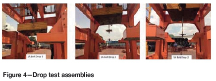
The objective of the dynamic performance tests was to assess the performance of the overall Garford hybrid dynamic bolt system under dynamic loading conditions. Each test consisted of dropping a mass of 3000 kg from a height of 750 mm onto a plate connected to the bolt specimen inside the steel installation tube. The kinetic energy input into the system was 22.06 kJ for each drop test. The testing rig in its actual configuration had a capacity of 3 t; the maximum velocity of 3.26 m/s was used in all tests. The total extension (mm), peak force load (kN), yield deflection (mm), and test time (seconds) were recorded. Figure 4 shows the detailed views of the test assemblies.
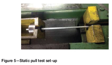
Static pull test procedures
All equipment and procedures were developed to meet or exceed the Deep Level Goldmine Standard Test Method for Laboratory Determination of Rock Anchor Capacities by Pull and Drop Tests. Two hydraulic rams with a capacity of 300 kN and total displacement of 300 mm were used. The hydraulic rams were operated, using an electric pump, from the initial phase of loading until the bolt failed, or the rams reached their stroke capacity (300 mm). Figure 5 displays the configuration of the electric pump with Garford bolt. The pressure of the hydraulic ram was measured at both ends of the test specimen (i.e. plate and toe ends) using electronic pressure transducers. All measuring instruments were connected to an automatic data-acquisition system and zeroed at the beginning of each test. A data sampling rate of 1 Hz was used.
Underground pull tests and quality control tests
Underground pull tests were conducted by assembling and attaching the pull gear at the collar of the bolts. The dial indicator was attached with the adjustable rod in line with the bolt axis to allow the bolt to be pulled directly down on the dial indicator, and the dial indicator was adjusted to zero. Immediately after the above steps, loading of the ram from zero to 3 t began and the recorded load and displacement were noted. Continuous pumping and recording of the load for each subsequent 0.05 mm displacement continued until the bolt yielded before full expansion of the ram, when the test was stopped.
Support requirements
A database of all reportable falls of grounds (FOGs) has been kept since 1995. Most of the FOGs occurred in the old conventional stopes and destress cuts, where areal coverage was not good. These records provided valuable information on the support requirements. The reach and capacity of the support was calculated on the 95th percentile of the conventional database (see Figure 6).
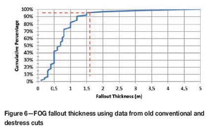
Figure 6 shows that the support should anchor above a height of 1.05 m (assuming the suspension theory). An appropriate mechanical anchor length of 1.8 m was chosen to ensure that the loose rock is properly anchored. The support resistance (SR) was calculated assuming a 1.05 m fallout thickness:

where
ρ is the density of the immediate hangingwall rock (2.68 t/m3)
t is the 95th percentile thickness of measured falls of ground (1.5 m)
g is acceleration due to gravity (9.81 m/s2).
Factor of safety for steel: 1.2
SR = (2.68*9.81*1.5*1.2)/(1 m*1 m) = 47.3 kN/m2
(required support resistance).
Brady and Brown 1993, stated that where peak ground velocities exceed 1 m/s, significant kinetic energy and momentum are imparted to the rock, resulting in potentially large displacements. Using the fallout thickness determined above as the potential depth of instability, it is possible to calculate the minimum energy absorption (EA) requirement per square metre of rock wall. The EA criterion for the hangingwall support system at the mine is 30 kJ/m2, based on:
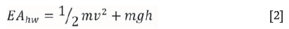
where
m is the mass of ejected rock (4020 kg/m2)
v is the anticipated peak ground velocity (3 m/s2)
h is the distance over which the energy is absorbed (0.3 m)
g is acceleration due to gravity (9.81 m/s2).
EAHW = 0.5*4020*9+(4020*9.81*0.3) = 29.9 kJ (required EA for hangingwall)
EASW = mgh = 4020*9.81*0.3 = 11.8kJ (required for sidewall).
Support configuration
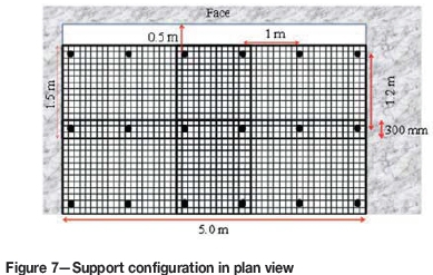
The support consists of weld mesh, with 5 mm thick strands and an aperture of 100 χ 100 mm, and 2.4 m long yielding anchors. The anchors are installed with 300 χ 280 mm faceplates and pre-tensioned to 30 kN at installation. This tensioning effectively stretches the mesh tight against the hangingwall and provides an active support. The Garford hybrid dynamic bolt spacing is 1 m across and 5 m along the width of the excavation and placed 1.2 m in the direction of the advancing face. The latter spacing fits the 2.4 m face advance. Support configuration in plan view is shown in Figure 7.
Yield support and test results
The Garford hybrid dynamic bolt is a ground reinforcement system that comprises a high-strength steel tube with a slot along its entire length. One end of the friction bolt is tapered to assist insertion into the hole, and the other end has a spherical steel collar to retain a bearing plate and the yielding portion at the end (see Figure 8).
Static pull test results
Five specimens were tested under static conditions to evaluate the installation method. The results obtained are presented as displacements vs load curves in Figures 9-13, and summarized in Table I.
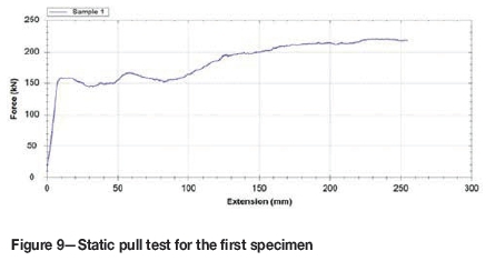
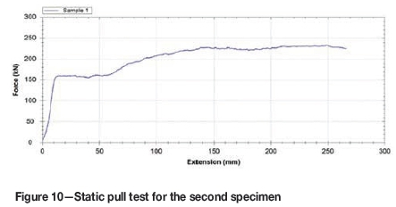
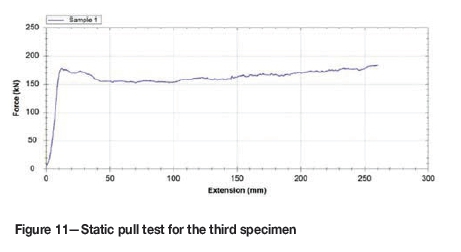
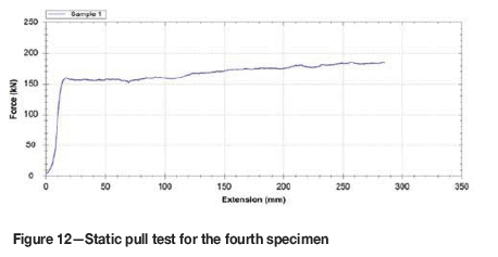
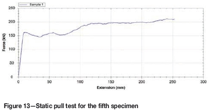
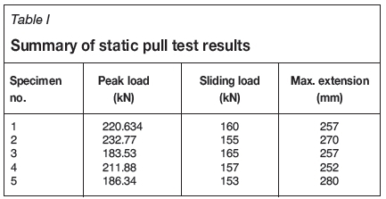
In all tests, after a short sliding distance, the dynamic device anchored into the split set bolt and then the load increased until the solid bolt began to be pulled through the dynamic device. From this test, it can be deduced that the Garford hybrid bolts were capable of withstanding a tensile load ranging from 183.53 kN (18.3 t) to a maximum of 232.77 kN (23.277 t) with a maximum extension of about 280 mm.
Dynamic impact drop test results
The drop test cycle is illustrated schematically in Figure 14. The results from a single drop configuration are summarized in Table II, and the results from tests on five specimens are presented in Figures 15-19. The first specimen withstood the first impact with a peak load of 191.79 kN, and the time taken for a test was 20.20 seconds, with a yield deflection of 221 mm. During this test, a maximum velocity of 3.26 m/s was achieved, with the energy absorbed being 22.06 kJ. After the test, no longitudinal cracks were observed along the bolts, unlike other types of bolt. The second specimen withstood the impact with a peak load of 217.95 kN and the time taken for a test was 21.10 seconds, with a yield deflection of 191mm. A maximum velocity of 2.9 0m/s was achieved with the energy absorbed being 22.09 kJ. Unlike the first and second tests, the third specimen withstood the impact with a peak load of 141.45 kN and the time taken for a test was 21.40 seconds, with a yield deflection of 228 mm. The maximum velocity was 3.28 m/s, with the energy absorbed being 22.12 kJ. The fourth specimen withstood the impact with a peak load of 138.18 kN and the time taken for the test was 17.50 seconds, with a yield deflection of 23 2 mm. During this test, a maximum velocity of 3.2 8m/s was achieved with 22.21 kJ energy absorbed. The last specimen was found to withstand the impact with a peak load of 157.98 kN and the time taken for a test was 20.50 seconds, with a yield deflection of 206 mm. The maximum velocity was 3.25 m/s and the energy absorbed 22.06 kJ. Figure 14 confirms the sliding of the dynamic device into the split set before plastic deformation of the solid bolt.
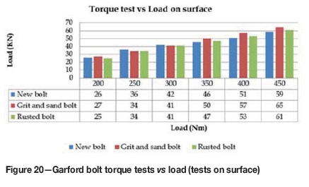
Torque tests
The laboratory torque test was conducted using nuts in different conditions, including rusted, new, and gritty nuts. The performance of all nuts was found to be effective and suitable for the bolts. Figure 20 shows the torque test performance on surface.
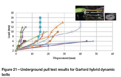
Underground pull tests
To investigate the behaviour of Garford bolts in actual mine conditions, underground pull tests were conducted. The results of the study indicated that, as expected from the surface test results, none of the tested bolts could withstand more than 160 kN, most of the bolts failing between 60 kN and 130 kN (see Figure 21). Only one bolt withstood 160 kN. Further underground investigations included torque tests and assessing the quality of installation.
Performance of Garford hybrid bolts under dynamic conditions
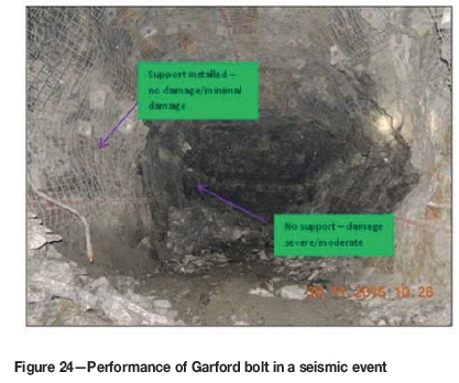
During the trials, several seismic events occurred ahead of the mining faces and in the back areas. Most of the areas affected by these events were found to be stable and the performance of the bolts was found to be effective. Although some of the bolts were noted to pull out from the in-stope pillar, the majority of the bolts managed to withstand several seismic events (see Figures 22-24).
Underground torque test results
Underground torque tests were conducted using a torque tester. The tests were assessed based on the number of turns in which the span rotated. The results of the study showed that five of the tested bolts out of seventy were not properly tensioned (the turns were either a half turn, full turn, or quarter turn) (see Table III).
Underground performance
The actual performance of the bolts underground was found to be different from that in surface tests. Several contributing factors to this were identified, including poor angle of installation, poor tensioning, the use of a larger drill bit than required, and highly fractured ground conditions which hampered proper installation. Poor support spacing was also found to contribute to the ineffectiveness of the Garford bolt in some area.
These issues have, to some extent, been addressed by providing sections with dedicated air compressors and hydraulic drilling machines. The bit size has been reduced to 41 mm to make it easily differentiable from the 45 mm blast-hole bit. It is also possible to fit standard drill-rod couplings into the 41 mm diameter support holes.
During the trials, several seismic events occurred ahead of the mining faces and also in the back areas. It was noted that most of the areas affected by events were found to be stable and the performance of the bolts were found to be effective. Although some of the bolts were noted to pull out from the in-stope pillar, majority of the bolts manage to withstand several seismic events (see Figure 23 and 24).
Conclusions
In order to determine the dynamic capability of the Garford hybrid bolt, static and dynamic tests were performed at the Videx Mining test facility in South Africa. The Garford hybrid bolt was found to withstand a maximum peak load of 217.9 5kN, with a minimum peak load of 138.18 kN; this was achieved in a test time of 17.50-21.40 seconds. Energy absorption ranged from 22.06 kJ to 22.21 kJ, with the velocities ranging from 2.90 m/s to 3.28 m/s. The maximum yield deflection of the bolts was found to range from 191 mm to 232 mm, indicating that the bolts were able to stretch adequately. The tensile tests have shown that the Garford hybrid bolts were capable of withstanding a tensile load ranging from 183.53 kN (18.3 t) to a maximum of 232.77 kN (23.277 t), with a maximum extension of about 280 mm. The underground performance of the bolts was different from that in the surface tests, but this was largely due to the quality of installation and ground conditions. Garford hybrid bolts were found to perform well during seismic events that occur at the vicinity of the mining faces and back areas.
Acknowledgements
The author is grateful to Mr Nin Nacker his support, and also the mine for facilitating the research. In addition, the participation of Mr Tawanda Zvarivadza in providing assistance and editing the work is also acknowledged.
References
Brady, B.H.G. and Brown, E.T. 1993. Rock Mechanics for Underground Mining. 2nd edn. Chapman & Hall, London. 571 pp. [ Links ]
Daehnke, A., Andersen, L.M., de Beer, D., Esterhuizen, G.S., Glisson, F.J., Grodner, M.W., Hagan, T.O., Jaku, E.P., Kuijpers, J.S., Peake, A.V., Piper, P.S., Quaye, G.B., Reddy, N., Roberts, M.K.C., Schweitzer, J. K., Stewart, R.D., and Wallmach, T. 1998. Stope face support systems. Final report for SIMRAC Project GAP 330. CSIR Division of Mining Technology. 407 pp. [ Links ]
Dyskin, A.V. and Germanovich, L.N. 1993. Model of rockburst caused by cracks growing near free surface. Rockbursts and Seismicity in Mines. Proceedings of the 3rd International Symposium, Kingston, Ontario, 16-18 August 1993. Young, R.P. (ed.). Balkema, Rotterdam. pp. 169-174. [ Links ]
Hoek, E. and Brown, E.T. 1980. Underground Excavations in Rock. Institution of Mining and Metallurgy, London. 527 pp. [ Links ]
Jager, A.J. and Ryder, J.A. 1999. A Handbook on Rock Engineering Practice for Tabular Hard Rock Mines. Safety in Mines Research Advisory Committee, Johannesburg. [ Links ]
Maxwell, S.C. and Young, R.P. 1997. Assessing induced fracturing around underground excavations using velocity imaging and induced seismicity. Rockbursts and Seismicity in Mines. Proceedings of the 4th International Symposium, Krakow, Poland, 11-14 August 1997. Gibowicz, S.J. and Lasocki, S. (eds.). Balkema, Rotterdam. pp. 179-183. [ Links ]
Mühlhaus, H.-B. 1990. Exfoliation phenomena in pre-stressed rock. Rockbursts and Seismicity in Mines. Proceedings of the 2nd International Symposium, Minneapolis, MN, June 1988 Fairhurst, C. (ed.). Balkema, Rotterdam. pp. 101-107. [ Links ]
McCreath, D.R and Kaiser, P.K. 1992. Current support practices in burst-prone ground (Task1). Technical Report to the Mining Research Directorate, Sudbury, ontario. 2 volumes, 94 pp. [ Links ]
Ortlepp, W.D. 1992. Invited lecture: The design of support for the containment of rockburst damage in tunnels - An engineering approach. Proceedings of the International Symposium on Rock Support in Mining and Underground Construction, Laurentian University, Sudbury, June 1992. Kaiser. P.K. and McCreath, D.R. (eds.), Balkema, Rotterdam. pp. 593-609. [ Links ]
Villaescusa, E. and Wright, J. 1997. Permanent excavation reinforcement using cement grouted split set bolts. Proceedings of the Australasian Institute of Mining and Metallurgy, vol. 1. pp. 65-69. [ Links ]
Villaescusa, E. and Wright, J. 1999. Reinforcement of underground excavations using the CT bolt. Rock Support and Reinforcement Practice in Mining. Proceedings of the International Symposium on Ground Support,Kalgoorlie, Western Australia, Australia, 15-17 March. Villaescusa, E., Windsor, C.R., and Thompson, A.G. (eds.), Balkema, Rotterdam. pp. 109-115. [ Links ]
Zvarivadza, T., Sengani, F., and Adoko, A.C. 2017. In-stope pillar scaling and fracturing in Southern African deep level gold mines. 26th International Symposium on Mine Planning and Equipment Selection (MPES2017), 29-31 August 2017, Luleá, Sweden, pp. 379-388. [ Links ] ♦
Paper received Mar. 2017
Revised paper received Jan. 2018

