


Services on Demand
Article
 English (pdf)
 Article in xml format
 Article references
Indicators

Related links
-
 Cited by Google
 -
 Similars in Google
Share

 Permalink
Journal of the Southern African Institute of Mining and Metallurgy
On-line version ISSN 2411-9717
Print version ISSN 2225-6253
J. S. Afr. Inst. Min. Metall. vol.118 n.3 Johannesburg Mar. 2018
http://dx.doi.org/10.17159/2411-9717/2018/v118n3a3
AFRIROCK 2017 INTERNATIONAL SYMPOSIUM
M. du PlessisI; D.F. MalanII
ILonmin Platinum, Marikana, South Africa
IIDepartment of Mining Engineering, University of Pretoria, South Afirca
SYNOPSIS
Crush pillars have been extensively applied on the Merensky Reef horizon since the late 1970s. Once in a crushed state, the residual strength of the pillar provides a local support function and must support the hangingwall to the height of the highest known parting. The design of crush pillars is mainly limited to specifying a width to height ratio (w:h) of approximately 2:1. It is also required that a pillar crushes close to the face, while the pillar is being formed. On many mines the crush pillar system is problematic owing to the difficulty of controlling pillar sizes. This is mainly caused by poor drilling and blasting practices. As a result, pillar crushing is not always achieved. Crush pillars are implemented at relatively shallow depth, the pillar dimensions have remained essentially unchanged over many years, and the impact of regional pillars and geological losses contributing to the regional behaviour of the rock mass are overlooked. In many cases the pillar system is the source of seismicity. In this paper, the influence of mining losses (potholes) and the use of sidings are discussed as possible contributors impacting on crush pillar behaviour. A limit equilibrium model implemented in a displacement discontinuity boundary element program is used to demonstrate crush pillar behaviour. The results are compared to the pillar behaviour at an underground investigation site, which supports the preliminary findings.
Keywords: crush pillar behaviour, limit equilibrium model, regional pillars, geological losses.
Introduction
Crush pillars have been extensively used in Merensky Reef stopes. The key function of the pillar system is to prevent the occurrence of back-breaks (large-scale collapses in the back area of a stope) occurring as a result of hangingwall separation along parting planes or fractures. One such problematic parting is the Bastard Merensky Reef, situated between 5-45 m above the Merensky Reef. The pillar dimensions are selected such that the pillars should be fractured while being formed at the mining face. This is typically achieved when a pillar is cut at a width to height (w:h) ratio of approximately 2:1 (Ryder and Jager, 2002). Once crushed, the residual strength of the pillar provides the required support function.
Factors influencing pillar stress {i.e. mining depth, pillar width, mining height, percentage extraction) will impact on crush pillar behaviour. Du Plessis and Malan (2015) demonstrated how oversized pillars could potentially result in unpredictable pillar behaviour. The execution of a mining layout can impact on the size of the pillar cut at the mining face. This is demonstrated by the examples and case study presented in this paper. Similarly, the presence of potholes or blocks of unmined ground will influence pillar crushing. While these are common occurrences on most mines using crush pillars, these factors have historically not been associated with poor pillar crushing or pillar seismicity.
Numerical analyses
A limit equilibrium model (Napier and Malan, 2014) implemented in the TEXAN displacement discontinuity boundary element code was used to simulate the impact of both geological losses and sidings on crush pillar behaviour. The model used was representative of the behaviour of crush pillars in a typical layout. This provided insights into when pillars will crush, where they will crush relative to the mining face, and why some pillars can potentially burst.
Mining and geological losses
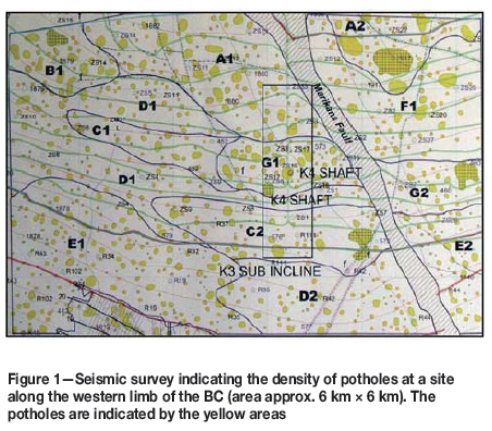
The effect of unmined blocks of ground or geological losses on crush pillar behaviour has not previously been considered as a factor affecting pillar crushing or pillar seismicity. For this reason, it was investigated in this study. In the platinum mines, intact blocks of ground are left in situ where poor ground conditions are encountered, or where geological features such as potholes are intersected. A pothole can be described as a random, approximately circular area where the reef slumps and pinches to such an extent that regular mining cannot be conducted. In the Bushveld Complex (BC), potholes make up the largest component of 'mining and geological' losses. Potholes can contribute to an extraction loss of between 5-25%. Figure 1 shows the pothole distribution at a site along the western limb of the BC. The potholes vary in size from 5-420 m in diameter. Most of the pothole diameters range between 20-100 m and the spans between adjacent potholes are typically less than 100 m.
To quantify the effect of a pothole adjacent to a line of crush pillars, an idealized crush pillar layout (Figure 2) was simulated. The layout consists of a 30 m χ 70 m stope panel with a second panel being mined in a sequential fashion adjacent to this first panel. The layout was simulated as eight mining steps with seven crush pillars being formed during this process. The unmined block was simulated as a square block, the dimensions of which [(x m) χ (y m)] were selected to simulate the percentage reef locked up in the area defining mining step 1 [e.g. pothole area (10 m χ 10 m)/(30 m χ 70 m) = 5%]. For the second panel, the size of each mining step was 10 m and the sizes of the crush pillars were 4 m χ 6 m. A 2 m mining height was used (w:h = 2:1). The element sizes were 0.5 m.

The parameters used for the simulations were as follows: Young's modulus 70 GPa, Poisson's ratio 0.25, contact friction angle 35°, intact and residual material strength 5 MPa, mining depth 600 metres below surface (mbs), and reef dip 0°. These values were chosen arbitrarily. The intent was to establish trends regarding the pillar behaviour, even though the parameters selected may not fully represent the underground environment. A sensitivity analyses was conducted to determine the effect of each input parameter on the behaviour of the model and simulated pillars in the layout. The results indicated that the choice of parameters produced qualitative agreement with observed crush pillar behaviour and historical underground measurements.
The results highlighted the importance of taking the geological environment into consideration when implementing a crush pillar system. The pillar stress is affected by the additional stability provided by unmined blocks of ground. This causes a reduction in the pillar stress and prevents effective pillar crushing. To overcome this would require the cutting of smaller pillars, which could be impractical.
The preliminary modelling results indicated that:
► Crush pillars implemented at a depth of 600 mbs with a w:h = 2:1 will not crush if a 10% mining loss is present adjacent to the pillar line. Pillars with a reduced width will be required in the area to ensure that pillar crushing is achieved (e.g. w:h = 1.5 is required at 600 mbs).
► Pillars located as far as 20 m behind or ahead of an unmined block will also be affected, resulting in either partially crushed (core still solid) or intact pillars.
► Crush pillars implemented at depths of more than 800 m below surface are impacted to a lesser extent when in close proximity to a pothole. Large mining losses (>10%) and potholes situated closer than 10 m from the pillar line can nevertheless prevent pillar crushing.
The case study presented in the second half of the paper indicated that a crush pillar situated in close proximity to a pothole at a depth of 1300 mbs was not in a crushed state.
The impact ofsidings
A siding is a 1-2.5 m wide ledge or heading carried on the one side of an on-reef development end, adjacent to the panel being mined (Figures 3 and 4). These sidings are typically carried at between 3 and 6 m behind the panel face (depending on the standard applied by the particular mining company). The main function of the siding is to either modify the fracture patterns resulting from high face stress or to move the crush pillars away from the travelling way, to prevent failed rock from falling on people. The sidings, being approximately 2 m wide, are difficult to clean (hand-lashed) and support. For this reason, mining of the siding is frequently behind schedule.
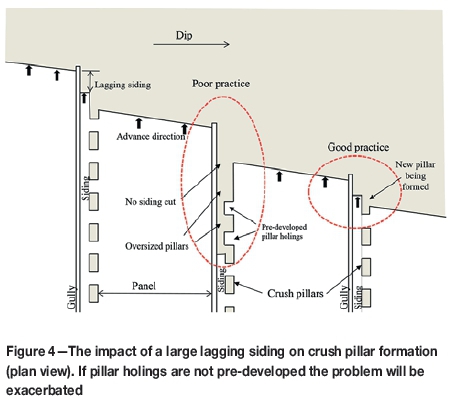
In some cases, sidings lag the face by 20-30 m and are then developed as a single mining face. A lagging siding will impact the width of the pillar being formed at the mining face (Figure 4). Until now, the impact of a lagging siding on the pillar width has not been identified as a contributor to undesired pillar behaviour, or a source of pillar seismicity.
Once the siding of an advancing panel lags behind the adjacent lagging panel face, oversized pillars are created. The pillars will be reduced in size to the required dimension only when the siding is blasted. At this point the pillar might not be able to crush sufficiently, as it is already in the back area of the stope.
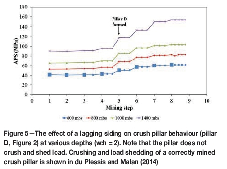
To investigate the impact of a lagging siding on crush pillar behaviour, the simulated mining sequence of the layout in Figure 2 was adjusted. The mining loss indicated in step 1 was excluded. A 2 m wide siding was added to the layout by initially simulating the pillars as being 6 m wide (w:h = 3). The siding was then mined by simulating the additional 2 m portion of pillar as being mined. The length of the oversized pillar resulting from a lagging siding was controlled by the delayed mining of the pillar holings. Initially a 6 m wide by 20 m long pillar was formed. The siding was mined, reducing the pillar width (at the pillar position) to 4 m (w:h = 2:1). The final pillar (2 m χ 4 m) was created only when the pillar holing was developed. This took place when the pillar was 20 m in the back area.
The layout was simulated at various depths as shown in Figure 5. All the results presented are for pillar D. Mining depth does not appear to have any impact on the overall behaviour of the pillar (although the pillar is subjected to a higher stress level). These findings illustrate how important it is to achieve pillar crushing while the pillar is close to, or is being formed at, the mining face. The results in Figure 5 can be compared to results presented by du Plessis and Malan (2014), where pillar crushing causes load shedding if the pillars are cut to the correct width.
The results indicate that a lagging siding could impact on pillar crushing. These pillars could therefore become sources of seismicity when located in the back area of a stope.
Case study supporting the simulated pillar behaviour
An investigation was conducted at a mine applying crush pillars on the Merensky Reef at a depth of approximately 1300 mbs. The objective was to verify some of the numerical modelling results and to investigate the failure mechanism of the pillars.
The mining layout requires 2.5 m wide χ 4 m long crush pillars, separated by a 2 m wide pillar holing. The stoping width is approximately 1.2 m high and the reef dips approximately 10° towards the north. Conventional breast mining is applied with long panels (approximately 35 m inter-pillar spans) being mined adjacent to a gully. A 2 m wide siding is cut adjacent to the pillar line. The mine standard requires that the siding does not lag the mining face by more than 4 m.
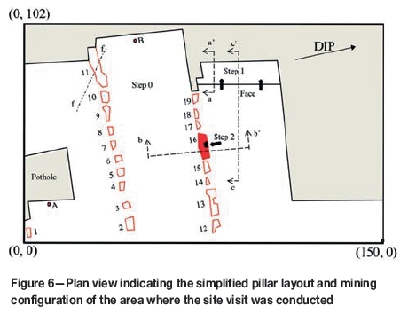
As can be seen in Figure 6, actual pillar dimensions varied greatly as a result of poor mining practice. Pillar 19 is approximately the correct dimension (2.5 m χ 3.8 m). Of the pillars cut, 63% had a width to height ratio greater than 2 and only four of the pillar holings were less than 2 m wide. The practice underground is to mine the pillar holings in an updip direction. The panel siding lag was kept at the 4 m standard. Accurate mining of the lagging panel was required to ensure that the pillars were cut to the correct dimension (pillar width). This was not done. The holings were also not always mined as required, impacting on the pillar length. This resulted in several significantly oversized pillars. Pillars 13 and 16 are examples of this. Pillars 17 and 18 were only split when the pillars were located some distance from the face. Pillars 13 and 16 are further examples of this bad practice. As a result, pillar 16 experienced a magnitude ML 1.9 seismic event. At the time of the event, the pillar holing indicated by the black square (step 2) and the holing between pillars 16 and 17 were being mined. Pillar 16, at this point was approximately 25-30 m in the back area.
The underground investigation revealed the following.
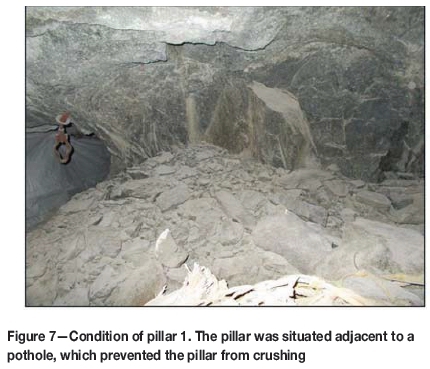
► Pillar 1, although adequately sized to ensure crushing (2 m χ 4 m), was in an uncrushed state as a result of its proximity to the pothole (Figure 7).
► The edge of the pothole was severely fractured due to the abutment stress (point A in Figure 6).
► Similarly, the face abutment at point B was also severely fractured. This face was left unblasted for approximately 5 months to rectify the lead-lag sequence.
► Pillar 11 was left oversized to clamp a fault. The pillar was in an unfractured state (similar to the condition of pillar 1). There were signs of footwall punching along the downdip side of the pillar.
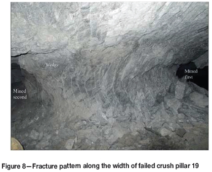
► Pillar 19, a newly cut pillar, was in a fractured state (Figure 8). The pillar displayed the same fracture profile as described by du Plessis and Malan (2016). As can be seen from the figure, the majority of the fractures propagated towards the side of the pillar which was exposed first. The side of the pillar exposed by the lagging face displayed little to no fracturing. Once the pillar is completely formed and the face advances, the fractures continue to dilate. Where fractures intersect at approximately the centre of the pillar, a wedge-like structure is formed.
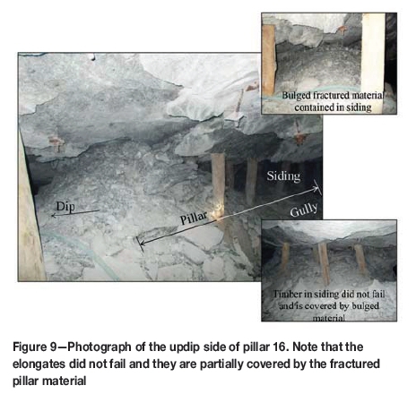
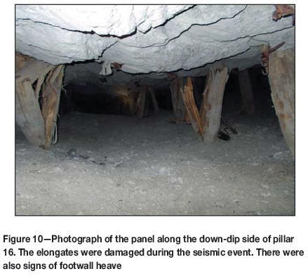
► Pillar 16 was, at the time of the investigation, in a completely fractured state. This was most likely a result of the seismic event. The updip side of the pillar bulged as the fractured material was pushed out (Figure 9). The downdip side of the pillar showed signs of ejected material scattered into the panel below. The footwall experienced heave and the timber support in the panel below the pillar was damaged as a result of the event (Figure 10).
Back-analysis
The underground observations supported some of the modelling results described in the previous section. It was nevertheless important to understand the failure mechanism contributing to pillar instability (i.e. pillar 16). The limit equilibrium model was also used to simulate the behaviour of the crush pillars for this particular underground layout. Du Plessis and Malan (2016) demonstrated that by applying this method, they successfully simulated the observed and measured behaviour of crush pillars for a large-scale underground trial site.
The layout for the underground investigation site (Figure 6) was approximated using straight line polygons to enable the area to be easily discretised using triangular elements. The mining steps considered were:
► Step 0: The layout with the face positions prior to the seismic event.
►Step 1: Panel advance to determine the effect on the pillar stress.
►Step 2: Mining of a 2 m χ 2 m slot into pillar 16 at the holing position to determine the impact on the pillar stress.
The element sizes selected for the mining steps were 1 m, and for the pillars 0.5 m. Following several successive cycles of parameter testing, the selected modelling parameters provided results which closely resembled the observed underground pillar behaviour. A dip of zero degrees was used in the model to simplify the analysis. The vertical stress at this depth was 38.5 MPa. The horizontal stress was assumed to be the same in both directions (k-ratio = 1.8). The intact and residual strengths of the limit equilibrium material were set to 1225 MPa and 20 MPa respectively. The high value for the intact strength is associated with the onset of pillar failure and was required to ensure that the model could replicate the observed underground pillar behaviour. A friction angle of 50° was used.
The numerical model was useful to establish trends and comparisons. The general results indicated that:
► The pothole adjacent to pillar 1 prevented the pillar from crushing.
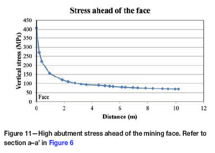
► High stresses were present along the solid abutments (Figure 11). This explains the significant scaling observed along the pothole edge and stopped panel face.
►The average convergence across the entire mining region was approximately 36 mm. It increased by approximately 1.5 mm during the extraction of mining step 1 and by another 1.5 mm during step 2. The additional convergence experienced during step 2 (mining of the slot along the pillar holing) was a result of pillar 16 crushing. It is insightful to note the impact which late pillar crushing in the back area has on the overall rock mass behaviour. This finding should be explored in more detail.
► The oversized pillars (11, 13, 16) were intact (e.g. Figure 12). Pillar 16 only fails in step 2 when the pillar is partially mined by the slot defining the pillar holing.
► Pillar 19 was completely crushed and in a residual state.

The vertical stress across pillar 16 (section b-b' in Figure 6) indicated that the pillar had high stress levels on the edge and an intact core. Mining of step 1 caused some additional damage to the pillar edge, as can be seen in Figure 12. The outer 0.5 m of specifically the updip side of the pillar (initially exposed side) assumes a residual state. As the outer edges of the pillar fail, the high edge stresses are transferred towards the core of the pillar. Once the slot along the planned pillar holing is mined (step 2), the pillar fails completely and enters a residual state.
A convergence profile across section b-b' is shown in Figure 13. A significant change in convergence is experienced across the pillar when the pillar fails (approx. 40 mm). Another convergence profile was constructed along section c-c', extending from the face position (including step 1) to 50 m in the back area of the mined-out panel, to also include the effect of pillar 16. The results show that the intact pillar has a significant impact on the convergence experienced in the panel in proximity to the pillar 16 position. Once the pillar fails, the convergence increases (step 2). However, there were other oversized intact pillars in the back area (i.e. pillar 13). As a result, a certain amount of convergence is prevented by the intact pillar. The system (pillar and rock mass) is therefore not at a state of equilibrium, and this can potentially result in violent pillar behaviour.

Du Plessis and Malan (2014) demonstrated the effect of oversized crush pillars in the back area of a stope. The findings indicated that if an oversized pillar did not crush at the face while being cut, as these pillars move into the back area as the mining face advances, they experience a higher stress level. The change in stress caused by a mining increment is lower than when the pillar is formed at the face. The pillar may therefore either not crush (especially when oversized) or fail violently. The stresses on these pillars in the back area are much higher and the loading environment has become much softer, as the pillar is no longer close to the face abutment. The results in Figure 14 provide an illustration of the increase in convergence as a result of possible violent crush pillar behaviour.

Du Plessis and Malan (2016) determined that the amount of convergence experienced in a crush pillar site could be directly related to pillar deformation (pillar fracturing or dilation along fracture planes). If the convergence (deformation) is restricted as a result of an intact pillar, it will impact on the amount of energy potentially available to cause violent pillar failure.
Salamon (1970) showed that the equilibrium between a pillar being loaded and the post-peak behaviour is stable irrespective of the convergence experienced by the pillar if:

where
k = Stiffness of loading strata (rock mass)
λ = Post-peak pillar stiffness.
Various stiffness criteria to ensure 'stable' pillar behaviour for rigid and yielding pillar systems were presented by Ozbay (1989), Ozbay and Roberts (1988), and Ryder and Ozbay (1990). Unfortunately, the literature and methodologies described do not fully support the behaviour of crush pillars and this needs to be further investigated. The preliminary analysis was therefore not included in the paper.
Conclusion
This paper illustrates the importance for crush pillars to enter a residual stress state while being formed at the mining face. Factors such as geological (i.e. potholes) or mining losses, in close proximity to the pillar, will impact on the behaviour of crush pillar. Furthermore, a lagging siding or delayed pillar holings will impact on the size of the pillar formed at the mining face. Early pillar crushing is therefore not achieved and this can result in unpredictable pillar behaviour.
The underground case study verified the preliminary modelling results. The model was able to replicate the behaviour of the pillars observed underground. It was insightful to note the impact of late pillar crushing in the back area on the convergence behaviour in the mined region. The study indicated that a reduced amount of convergence, as a result of an intact pillar, may be indicative of potential violent pillar failure. This finding should be further explored.
Acknowledgements
Part of the work described in this paper formed part of Dr Michael du Plessis' PhD studies at the University of Pretoria. The contribution of Professor John Napier with regard to the development of the limit equilibrium model as well as the TEXAN code is acknowledged.
References
Du Plessis, M. and Malan, D.F. 2014. Evaluation of pillar width on crush pillar behaviour using a limit equilibrium solution. Proceedings of the 2014 ISRMEuropean Rock Mechanics Symposium (Eurock 2014), Vigo, Spain, 27-29 May. CRC Press, Leiden, The Netherlands. [ Links ]
Du Plessis, M. and Malan, D.F. 2015. Designing controlled pillar failure - crush pillar support. Journal of the Southern African Institute of Mining and Metallurgy, vol. 115. pp. 481-488. [ Links ]
Du Plessis, M. and Malan, D.F. 2016. The behaviour of Merensky crush pillars as measured at a trial mining site. Proceedings of EuRock 2016, Cappadocia, Turkey. International society for Rock Mechanics. [ Links ]
Napier, J.A.L. and Malan, D.F. 2014. A simplified model of local fracture processes to investigate the structural stability and design of large-scale tabular mine layouts. Proceedings of the 48th US Rock Mechanics / Geomechanics Symposium, Minneapolis, USA. American Rock Mechanics Association, Alexandria, VA. [ Links ]
Ozbay, M.U. 1989. The stability and design of yield pillars located at shallow and moderate depths. Journal of the South African Institute of Mining and Metallurgy, vol. 898, no. 3. pp. 73-79. [ Links ]
Ozbay, M.U. and Roberts, M.K.C. 1988. Yield pillars in stope support. Proceedings of the SANGORM Symposium in Africa, Swaziland. South African National Institute for Rock Mechanics. pp. 317-326. [ Links ]
Ryder, J.A. and Ozbay, M.U. 1990. A methodology for designing pillar layouts for shallow mining. Proceedings of the International Symposium on Static and Dynamic Considerations in Rock Engineering, Swaziland. International Society for Rock Mechanics. pp. 273-286. [ Links ]
Ryder, J.A. and Jager, A.J. 2002. A Textbook on Rock Mechanics for Tabular Hard Rock Mines. Safety in Mines Research Advisory Committee, Johannesburg. [ Links ]
Salamon, M.D.G. 1970. Stability, instability and design of pillar workings. International Journal of Rock Mechanics and Mining Sciences, vol. 7. pp. 613-631. [ Links ] ♦
This paper was first presented at the AfriRock 2017 International Symposium, 30 September -6 October2017, Cape Town Convention Centre, Cape Town.

