


Serviços Personalizados
Artigo
 Inglês (pdf)
 Artigo em XML
 Referências do artigo
Indicadores

Links relacionados
-
 Citado por Google
 -
 Similares em Google
Compartilhar

 Permalink
Journal of the Southern African Institute of Mining and Metallurgy
versão On-line ISSN 2411-9717
versão impressa ISSN 2225-6253
J. S. Afr. Inst. Min. Metall. vol.118 no.3 Johannesburg Mar. 2018
http://dx.doi.org/10.17159/2411-9717/2018/v118n3a1
AFRIROCK 2017 INTERNATIONAL SYMPOSIUM
Early assessment of dynamic rupture hazard for rockburst risk management in deep tunnel projects
M.S. Diederichs
Department of Geological Sciences and Geological Engineering, Queen's University, Kingston, Canada
SYNOPSIS
Managing rockbursting conditions in mine development and operational environments is a complex and difficult challenge. The hazard and the associated risks can be managed based on local experience, monitoring, and informed data-rich analysis. On the other hand, blind development for deep tunnelling is being carried out around the world at depths in excess of 2 km and rockbursting has become a common and serious challenge. The rockburst mechanism is predominantly tunnelling-induced dynamic rupture or strain bursting, distinct from the remote or mine-generated events that impact mining excavations. Considerations of rock petrology, fabric, mechanical parameters, and structure allow an estimate of brittle response. The potential for energy storage and rapid release must be accounted for in order to understand the burst potential early in the basic design stage for deep tunnels. Failure to do so can result in unsafe conditions and years of delay. In this paper a multistep semi-empirical approach for early assessment of strain burst or dynamic rupture potential along deep tunnel alignments in variable ground is presented.
Keywords: tunnelling, high stress, dynamic rupture, rockburst, hazard assessment, risk management.
Introduction
Rockbursts are explosive failures of rock which occur when high stress concentrations are induced around underground openings (Hoek, 2006) in brittle rock or rock masses with brittle structure. The Canadian Rockburst Handbook (Kaiser, McCreath, and Tannant, 1996) defines a rockburst as: 'damage to an excavation that occurs in a sudden or violent manner and is associated with a seismic event'. Codelco (2008) uses the following definition of rockburst: 'Loss of continuity of the production process of the mining operation, caused by the rupture and instant projection of the rock mass, associated with a seismic event.' It is important to note the evolution, through these three definitions, from a term describing a mechanical phenomenon to a general and then a specific form of damage causing defined consequences. From a hazard and risk management perspective it is important to maintain a separation between the physical process of 'dynamic rupture' of the rock around a tunnel (the hazard) and the operational 'rockburst' impact (risk). The assessment of the hazard of dynamic rupture is the subject of this paper.
In mining, there are many different mechanisms that lead to rockbursts. Pillar failure can be very violent if the pillar core reaches capacity and the mine geometry is such that instantaneous deformations (system unloading) are large. Large stress changes associated with large-scale mining can result in fault slip distant from the drift or shaft but capable of inducing sympathetic strain-bursts (due to stress wave propagation) or seismically induced falls of ground involving previously damaged rock.
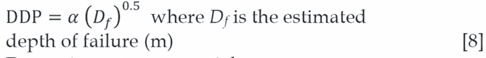
In tunnelling, however, the most important mechanism, is 'strain bursting' (Kaiser, McCreath, and Tannant, 1996) of walls and the tunnel face, with or without structural control and as a result of the complex stress path within the near-field rock as the tunnel advances (Diederichs, Eberhardt, and Fisher, 2013). In this case the stress changes, energy storage, and release mechanisms are often coincident and local to the tunnel boundary. This mechanism is one of dynamic rupture of a competent rock at high induced stress around the tunnel, as shown in Figure 1.
The extent and dynamic intensity of the failure can be mitigated by (or enhanced by) structural, compositional, and geometrical components within the rock-tunnel system. The dynamic rupture event can be self-triggered (spontaneous failure of rock with rapid release of stored strain energy), or can be triggered by a seismic strain wave from more distant structures or excavation influence zones.
Kaiser, McCreath, and Tannant (1996) classify low-, medium-, and high-level strain bursts (termed here 'dynamic rupture events') as involving depths of rupture less than 0.25 m, 0.75 m, and 1.5 m, respectively. Depths of rupture greater than 1.5 m represent an extreme event in a tunnelling context (for a tunnel span of 5-10 m). The minimum ejection velocity for a classification of strain burst is 1.5 m/s. Kaiser, McCreath, and Tannant consider velocities greater than 3 m/s to be very high in the context of self-triggered dynamic rupture, although higher velocities can be generated through ejection of rock due to the transfer of energy from shock waves from a distant event. For self-triggered events, kinetic energies greater than 10 kJ per square metre of tunnel surface are considered high, and energies greater than 35 kJ/m2 are considered extreme (with respect to modern support technology). The classification of potential intensity for a dynamic rupture event should be considered in the absence of support. The real intensity of a strain burst is impacted by the effectiveness of reinforcement and support elements (within the rock and on the rock surface).
Dynamic rupture mechanics
Most of the discussions on rockburst damage in mining environments have been based on the primary mechanism of a remote seismic event, triggered by large-scale mine stoping, and the effect on a tunnel within the mine infrastructure. For tunnelling not associated with mining, the primary source of seismicity is the rock mass around the tunnel itself. It is possible for the stress changes and blasting associated with a large isolated tunnel to generate structural seismicity some distance away from the active heading, although for a single-heading tunnel, far more common are strain bursts (dynamic rupture events) at or near the active tunnel face. These events can involve the bulking of fractured rock or can be primarily ejection-based.
In terms of understanding and likelihood assessment, it is important to understand the mechanics of rockbursting in terms of the components:
► Stress concentration (geometry, geology, structural creep)
► Deconfinement (tunnel perimeter/face geometry)
► Energy storage (high strength capacity, structural resistance)
► Failure (brittle intact rock or brittle failure of structural interlock)
► Rapid release (stiff rock or soft surroundings, rapid coalescence through structure)
► Volume (instantaneous yield or release of structural integrated volume).
Stress concentration
Stress concentrations around a tunnel perimeter can be simple or complex, depending on the geology at the tunnel boundary away from the advancing face. According to the classic formula for maximum wall stress, in terms of the principal stresses within the plane of the tunnel section:

In the case of a vertical principal stress the following equations can be used:

For a circular opening, A=B=3. For a square opening assume A=5=2, although stresses at the corners of the excavation will be higher than those predicted at the roof or walls. These high corner stresses can create hazards where bedding or persistent jointing is present and sub-parallel to or slightly inclined to the surface of the excavation (including the face). For narrow arched tunnels with height similar to or slightly greater than the span, A=3.5 while 5=2.5. For typical wider tunnels (span greater than height), A=2 and 5=4 provide a starting estimate.
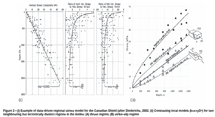
For predictive analysis early in a project it is useful to combine these simple equations for maximum induced stress with functions (of location or depth) defining the in-situ stress state (in a plane perpendicular to the tunnel for initial 2D assessment). Examples of stress models from the Canadian Shield and from the Andes Mountains (Chile) are shown in Figure 2. These can then be used to predict the potential for rock yield (depth) from empirical tools or more rigorous analysis.
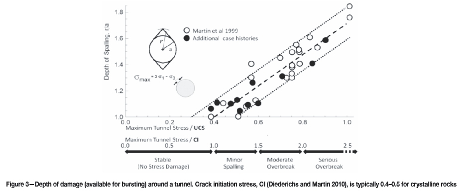
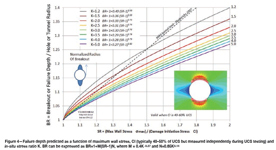
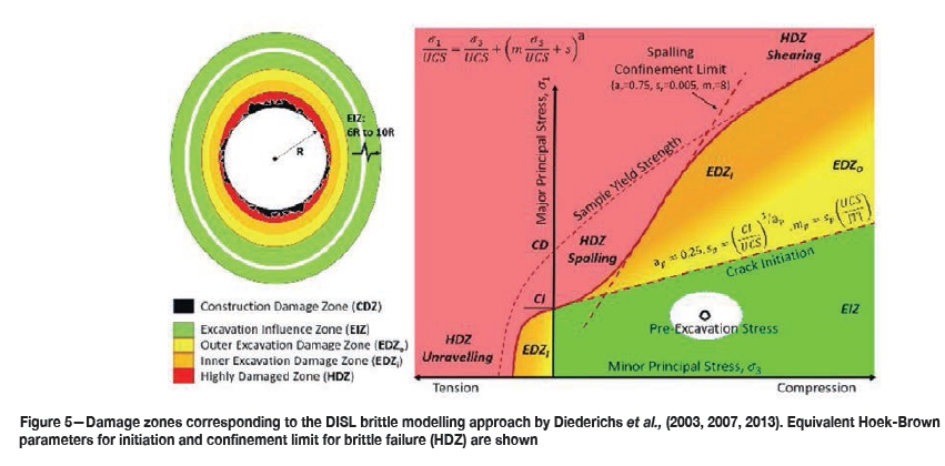
Figure 3 depicts a now classic predictor for the maximum volume of rock around a tunnel available for release in a rockburst, using the maximum tunnel stress calculated in the previous step. Figure 4 shows results from a more rigorous numerical analysis and can be used to estimate the maximum failure depth and the angular extent of failure for a circular tunnel (see functions in caption). These functions are obtained through the brittle yield approach by Diederichs (2007) using a nonlinear finite element code and the peak and residual parameters described in Figure 5.
In order to use the relationships in Figure 4 the following procedure can be used:
1. Obtain an estimate of principal stresses σ1 and Φ in a 2D plane perpend icular to the tunnel.
2. Obtain damage threshold CI for rock types along tunnel (Use ϋ,5 * UCS if no data exists).
3. Calculate the strength ratio:

4. Use the in-plane in-situ stress ratio

5. Calculate calibration factors:

6. Calculate breakout ratio:

7. Predicted depth of failure;

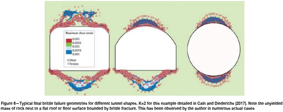
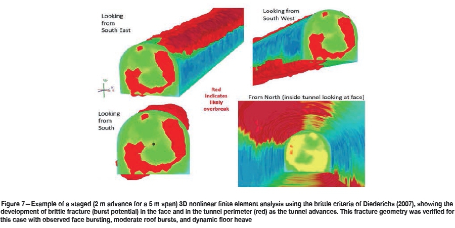
Simple 2D analysis of typical tunnel shapes is recommended to confirm estimates of failure depth, D/i especially for non-circular geometries. Using a brittle-yield criterion (Diederichs 2007) the influence of geometry can be determined as in Figure 6. The sequence or timing of brittle fracture development in the face and tunnel perimeter with respect to advance can be analysed using 3D finite element analysis as in Figure 7.
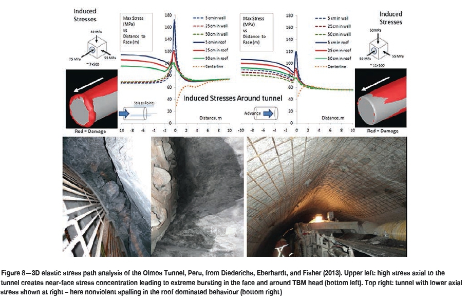
The 3D nature of in-situ stress may be important for the prediction of dynamic rupture. Figure 8 illustrates a tunnel case in Peru (Diederichs, Eberhardt, and Fisher, 2013) where the major stress rotated from perpendicular to axial with respect to the tunnel axis due to the crossing of a tectonic thrust. In the latter case the major bursting moved from the tunnel roof to the face due to a high perimeter stress spike during advance.
Deconfinement
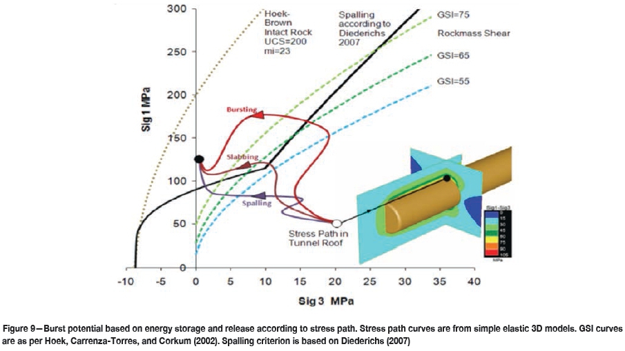
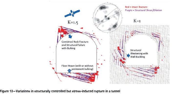
As shown in Figure 4, brittle fracturing is very sensitive to confinement. The loss of confinement (normal to the tunnel boundary) enhances the brittle failure caused by stress concentrations parallel to the tunnel surface, creating the potential for violent buckling or sudden asperity rupture and shear as rockburst mechanisms. Deconfinement of subparallel structure with increased coplanar stress during excavation can lead to sudden failure as the effects of small interlocking asperities are nullified by small amounts of dilation. Flat walls and corners are not ideal in a high-stress environment, as seen in Figure 5. In addition, deconfinement due to overscaling and the loss of a smooth excavation profile can lead to unpredictable and dynamic failure, particularly in ground with jointing (or bedding). Maintaining the excavation profile and providing for some minimum curvature on all surfaces is recommended. The orientation of in-situ stress and the tunnel geometry can affect the stress path such that strain energy (see the next section) can be stored and then released suddenly, as in Figure 9.
Energy storage
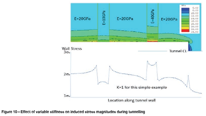
An issue related in some ways to the deconfinement factor is that of energy storage. Geometry and stress state can play a large part in the ability of a rock mass or a local structure to store strain energy during the excavation cycle. Figure 9 illustrates the concept of energy storage and release based on in-situ stress orientation and magnitude and the deconfinement associated with the stress path. Figure 10 illustrates the variability in induced stress as a tunnel passes through heterogeneous ground with contrasts in stiffness. Energy is stored in the softer units but transferred to the stiffer units as they reach critical stress first. Stiffness contrasts result in face bursting and near-face dynamic rupture as the tunnel advances
Brittle failure
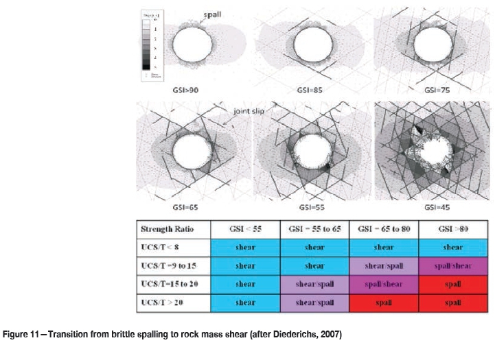
For massive or moderately jointed rock with a high ratio of compressive to tensile strength, brittle spalling damage initiates (Diederichs, 2003, 2007) at a wall stress of around 40-60% of the intact UCS, following the 'spalling criterion' in Figure 11. Closely spaced fractures with random orientations oblique to the tunnel face and wall result in 'rock mass shear' behaviour (Figure 11). This is reflected in the 'spalling' and 'rock mass shear' envelopes in Figure 9. The first envelope to be intersected by the stress path will govern the mode and extent of failure.
Spalling is a brittle damage and yield process but does not necessarily lead automatically to a violent failure event or dynamic rupture (strain burst). For this to occur at a scale that poses a design and safety challenge, there must be energy storage and instantaneous release.
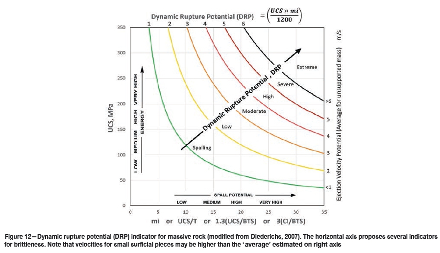
Without considering heterogeneity, geometry, and structure for the moment, it is possible to rank rock types with respect to their dynamic rupture potential (DRP) based on their brittle character, represented by the ratio of UCS to T (true tensile strength or estimate from Brazilian tensile strength such that T=BTS/1.3, after Perras and Diederichs, 2014), and the capacity for energy storage, represented simply by unconfined strength (Figure 12).
Energy release and volume
Brittle failure in massive ground around a circular tunnel with an anisotropic stress field will be self-limiting in size and may also be progressive in its failure mode (many smaller dynamic releases making up a major overbreak). Geometrical variances such as flat walls, loss of profile due to ground fall and overscaling, and excess round length can increase energy release rate and volume. Structure is a major contributor to instantaneous energy release (as well as storage) and can also drastically increase the volume of rock that can spontaneously fail as the structure interacts with induced rock fracture.
Dynamic rupture hazard assessment
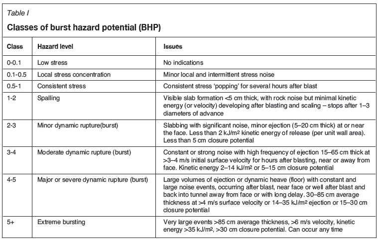
The hazard assessment used in this paper is based on a recommended ranking from 0 to 4+ to describe the level of hazard due to dynamic rupture, as summarized in Table I, based primarily on mining guidelines by Kaiser, McCreath, and Tannant (1996), modified by the author for blind tunnelling (span 5-10 m) and updated to account for modern burst support capabilities. Energy demand is the prime indicator of hazard level in Table 1 - other indicators are non-unique and illustrative only.
The initial step for hazard assessment is to combine the depth of predicted failure, Df, with the potential for dynamic rupture, DRP. In order to end with a ranking consistent with Table I, the following relationship has been developed and validated by the author through case histories in Chile and Peru:
Damage depth potential:
DDP = a (Df)°5 where Df is the estimated
Dynamic rupture potential:
Suggested empirical constants to match Table 1 (can be calibrated for local conditions): α =4.5; β=1
Burst hazard potential:

Adjustment for structural control
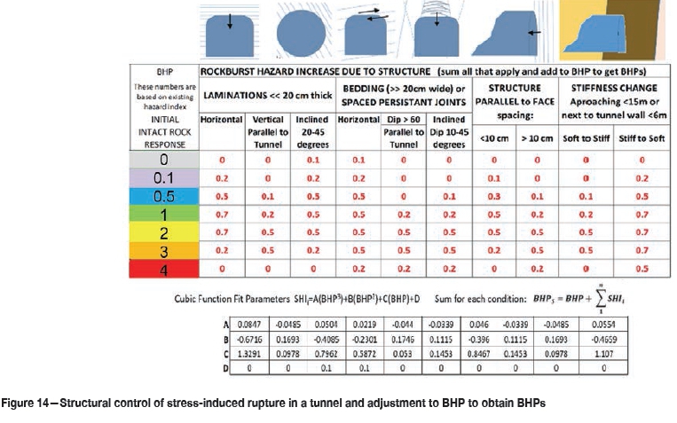
Some discrete structures with unfavourable orientations can enhance the energy storage and rapid release potential as well as increasing the volume of failure. Based on experience with tunnels in Chile, Peru (Diederichs, Eberhardt, and Fisher, 2013), Canada, and Switzerland, a scheme has been developed to estimate the added hazard potential, based on the initial BHP for intact rock, due to structure as shown in Figure 14. These observationally validated adjustments, while approximate and empirical, can be summarized by a generalized cubic function as shown. The structural hazard increments, SHIi, calculated for each dominant class of unfavourable structure are summed and the result added to the initial BHP. If desired, each SHIi can be multiplied by a factor from 0-1, where zero indicates the absence of structure and unity indicates fully dominant and pervasive structure.
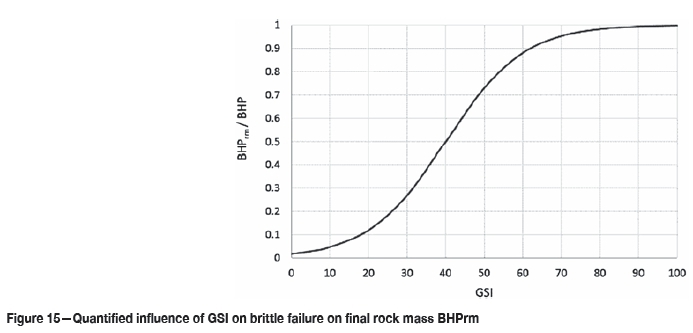
Finally, the impact of ubiquitous, softening structure must be considered. The structures above are normally fresh and unaltered features (possibly infilled with hard minerals). Dense isotropic structure and weathering can be considered through GSI. The impact (as a multiplier) of GSI on bursting can be approximated by the function in Figure 15. Low GSI reduces BHP while increasing squeezing potential.
BHPs is calculated by summing the individual structural hazard increments (for each major controlling class of structure) and adding the sum to the base BHP (calculated for intact rock) in order to integrate the impact of structural control on the bursting process:

The impact of softening structure (through GSI) is then included through a factoring of BHPs to obtain the final ranking BHPrm for the whole rock mass and structural system:

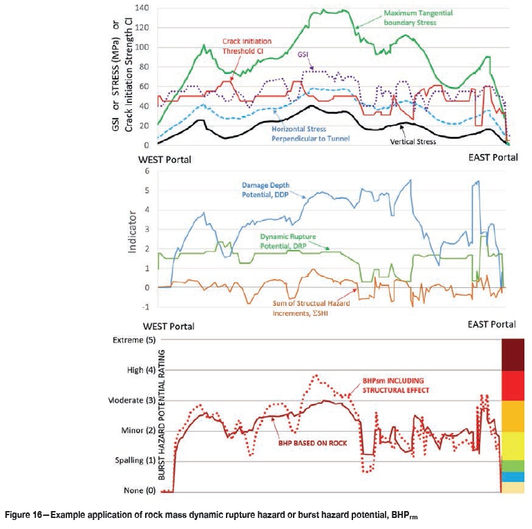
This process of initial hazard assessment, facilitated by Equations [1] through [12], can be integrated easily into a spreadsheet format where rock and structural information can be input from borehole logs, surface exposures, or refined geological modelling and structural assumptions (to be verified as observational data becomes available). Stress values along the tunnel alignment can be calculated from the tunnel orientation and a functional stress model for the local area and depth. The resulting assessment and hazard prediction for an example project (a deep Andean tunnel in the preconstruction stage) based on available knowledge is shown in Figure 16.
Managing hazard and risk
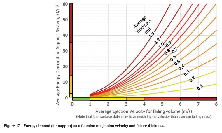
This is of course a qualitative assessment of hazard and the definitions of the hazard level, summarized for this work in Table I, are open to informed debate, and the indicator thresholds of energy demand, ejection velocity, and failure volume constituting each level will evolve gradually over time as routinely available and economical support technology improves. Using Table I as a basis, the primary indicator of severity for dynamic rupture or strain burst event is the excess energy demand (not including energy consumed by yielding rock and any functioning support present) per unit surface area. This can be back-calculated for verification based on the relationship in Kaiser, McCreath, and Tannant (1996):
where t = average failing thickness
ρ = density of the rock
d = horizontal ejection distance (observed limit of main ejected mass)
h = vertical height limit of main failure volume (pre-event)
θ = angle (negative down from horizontal) of initial ejection trajectory*
'equation is valid only for trajectories from -45 to +89 degrees
This relationship is graphically illustrated in Figure 17.
The reader is referred to Kaiser, McCreath, and Tannant (1996), Potvin and Wesseloo (2013), Cai (2013), and Villaescusa, Player, and Thompson (2014) for more discussion on the design of dynamic support. Kaiser, McCreath, and Tannant (1996) advocated a multipurpose support system consisting of:
► Stiff reinforcement functionality to maintain rock mass integrity and internal strength
► Dynamic displacement capacity and energy capacity in the event of violent rupture, and
► ntegrated surface retention to resist uncontrolled bulking and to ensure energy transfer.
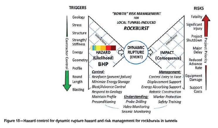
Support design is only one component of a management strategy for dynamic rupture hazard and rockburst risk. It is beyond the scope of this paper to explore all mitigation strategies in depth, but Figure 18 lays out the options. The hazard is assessed based on the triggers as outlined in this paper. The likelihood of dynamic rupture and the magnitude of the rupture events can be controlled to some degree through the 'Control' options listed in Figure 18. Anticipation of hazardous conditions can be informed by probe drilling, and the nature of the hazard can be verified by seismic monitoring and video recording (of the face area) during the construction cycle.
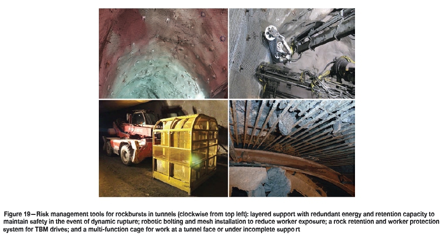
In many conditions, some level of dynamic rupture is inevitable and cannot be engineered away. In this case, the impact must be mitigated through the 'Management' options shown in Figure 18. Some management strategies may result in costs, delays, or other issues that would also be considered 'risks'. The right side of the figure highlights the priority in which risk must be viewed, and in many cases certain risks (damage to robotic support installation equipment, for example) can be viewed as acceptable if they reduce the potential for more critical risk such as project shutdown, injury, or death. Figure 19 illustrates a number of risk management strategies that can be used when the potential for dynamic rupture hazard cannot be avoided.
Conclusions
A multi-step methodology has been developed for early prediction of dynamic rupture or strain burst potential along the alignments of deep tunnels in variable ground conditions. Although the approach is empirical, based on past work and on the experience of the author in active tunnelling cases, it is designed to allow for calibration to regional experience with geological environments beyond the scope of the Andean, Alpine, and Cordilleran experience upon which it is based. The approach considers stress concentration, tendency of the intact rock to yield in a brittle manner, and sudden energy release upon failure. In addition, discrete structural configurations likely to increase the probability or magnitude of dynamic energy release are considered through a hazard increment that can be based on drill core, if available, or on a sound geological model with attention to lithological contacts and likely geological structures. The influence of more intense random or isotropic joints and fractures is accounted for by a function of GSI (where a lower GSI reduces the potential for bursting while possibly increasing the potential for other stress instabilities such as squeezing).
The burst hazard potential system developed by the author and presented here results in an index or ranking for potential dynamic rupture that is consistent with those previously published by others for support in bursting ground. The BHP rankings can be used directly to apply corresponding rockburst support recommendations such as those by Kaiser, McCreath, and Tannant (1996), Cai (2013), Potvin and Wesseloo (2013), and others.
References
Cai, M. 2013. Principles of rock support in burst prone ground. Tunnelling and Underground Space Technology, vol. 36, no. 6. pp. 46-56. [ Links ]
Cain, S. and Diederichs, M.S. 2017. Shape matters: the impact of geometry on brittle damage for repository engineering. Tunnels and Tunnelling, 2017, no. 2. pp. 32-37. [ Links ]
Codelco. 2008. Procedimiento General para Emergencias por Estallido de Roca en la Mina. Informe GMIN-GRL-P-005 con fecha mayo de 2008, Version 3. [ Links ]
Diederichs, M.S. and Martin, C.D. 2010. Measurement of spalling parameters from laboratory testing. Proceedings of Eurock 2010, Lausanne, Switzerland, 15-18 June 2010. Taylor & Francis, London. pp. 323-326. [ Links ]
Diederichs, M.S. 2002. Stress induced damage accumulation and implications for hard rock engineering. Proceedings of 'NAHMS 2002, Toronto. Hammah, R., Bawden, W.F., Curran, J., and Telsnicki, M. (eds). University of Toronto Press. pp. 3-14. [ Links ]
Diederichs, M.S. 2007. The 2003 Canadian Geotechnical Colloquium: Mechanistic interpretation and practical application of damage and spalling prediction criteria for deep tunnelling. Canadian Geotechnical Journal, vol. 44, no. 9. pp. 1082-116. [ Links ]
Diederichs, M.S., Eberhardt, E., and Fisher, B. 2013. Consideration of stress and structural influence on high stress response in deep tunnelling - the Olmos Tunnel, Peru. Underground. The Way to the Future. Proceeding of the World Tunnel Congress, Geneva, Switzerland. Anagnostou, G. and Ehrbar, H. (eds). CRC Press. pp. 1998-2005. [ Links ]
Hoek, E. 2006. The development of rock engineering. https://www.rocscience.com/documents/hoek/corner/02_The_development _of_rock_engineering.pdf [ Links ]
Hoek, E., Carrenza-Torres, C.T., and Corkum, B. 2002. Hoek-Brown failure criterion - 2002 edition. Proceedings of the ARMS-TAC Joint Conference, Toronto, Canada. pp. 267-273. [ Links ]
Kaiser, P.K., McCreath, D.R., and Tannant, D.D. 1996. Canadian Rockburst Support Handbook. Canadian Rockburst Research Program, Vol II, Book I (1990-1995). Canadian Mining Industry Research Organization, Sudbury, Ontario. 343 pp. [ Links ]
Martin, C.D., Kaiser, P.K., and McCreath, D.R. 1999. Hoek-Brown parameters for predicting the depth of brittle failure around tunnels. Canadian Geotechnical Journal, vol. 36, no. 1. pp. 136-151. [ Links ]
Perras, M.A. and Diederichs, M.S. 2014. A review of the tensile strength of rock: concepts and testing. Geotechnical and Geological Engineering, vol. 32, no. 2. pp. 525-546. [ Links ]
Potvin, Y.H. and Wesseloo, J. 2013. Towards an understanding of dynamic demand on ground support. Journal of the Southern African Institute of Mining and Metallurgy, vol. 113, no. 12. pp. 913-922. [ Links ]
Villaescusa, E., Player, J.R., and Thompson, A.G. 2014. A reinforcement design methodology for highly stressed rock masses. Proceedings of the 8th Asian Rock Mechanics Symposium,, Sapporo, Japan, 14-16 October 2014. American Rock Mechanics Association. pp. 87-94. [ Links ] ♦
This paper was first presented at the AfriRock 2017 International Symposium, 30 September-6 October 2017, Cape Town Convention Centre, Cape Town.

