


Services on Demand
Article
 English (pdf)
 Article in xml format
 Article references
Indicators

Related links
-
 Cited by Google
 -
 Similars in Google
Share

 Permalink
Journal of the Southern African Institute of Mining and Metallurgy
On-line version ISSN 2411-9717
Print version ISSN 2225-6253
J. S. Afr. Inst. Min. Metall. vol.118 n.1 Johannesburg Jan. 2018
http://dx.doi.org/10.17159/2411-9717/2018/v118n1a9
PAPERS OF GENERAL INTEREST
A yielding bolt-grouting support design for a soft-rock roadway under high stress: a case study of the Yuandian No. 2 coal mine in China
X. SunI; L. WangI; Y. LuI; B. JiangI; Z. LiI; J. ZhangII
IState Key Laboratory for Geomechanics and Deep Underground Engineering, China University of Mining and Technology, China
IIFaculty of Architecture and Civil Engineering, Huaiyin Institute of Technology, China
SYNOPSIS
The stabilization of roadways in soft rock under high stress has always been a major concern for deep underground coal mines. This paper describes a case study focusing on the stability of a soft-rock roadway in Yuandian coal mine in Anhui Province, China. The Beiyi main return roadway in this mine was primarily supported by U-steel support; however, considerable deformation and severe failures occurred. Therefore, a new support design, the yielding bolt - grouting support design, was proposed based on the physical and mechanical parameters, in situ stress measurements, and the failure characteristics of the roadway. The mechanics of the yielding bolt - grouting support was analysed and compared to the normal bolt - grouting support. A field experiment was conducted in a 100 m long section of the roadway. The monitoring results showed that compared with the old support, the new support design reduced the deformations of roof, floor, and rib by 41.4%, 56.1%, and 64.7% respectively, and the maximum deformation rate decreased from 15.12 mm/d to 9.28 mm/d. This case study indicates that the yielding bolt - grouting support design is an effective method to support roadways in soft rock under high stress.
Keywords: stabilization, soft roadway, yielding bolt, grouting, U-steel support.
Introduction
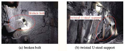
The stabilization of roadways in soft rock under high stress has been a major concern in deep underground coal mines (He, 2014; Li et al., 2015). Especially after absorbing underground water or water vapour, the rock surrounding these roadways undergoes considerable weakening and swelling (Erguler and Ulusay, 2009; Wasantha and Ranjith, 2014). Under high overburden and tectonic stresses, the roadway and the surrounding rock commonly display the following characteristics: (a) large displacements, (b) high deformation rates, and (c) long deformation time (Lu et al., 2010; Kang, Liu, and Xi, 2014). The conventional support structure cannot adapt to the excessive deformation, which leads to damage of the support structure (loosening or breaking of the bolts, twisting of the U-steel legs). The instability of the roadway not only reduces its functionality, but also constitutes a safety hazard.
Numerous studies have investigated the deformation and failure mechanisms in deeply buried soft-rock roadways (He, 2014; Guo, Qian, and Wang, 2009; Gao et al., 2010; Shen, 2014; Jiang et al., 2015; Wang et al., 2016). The deformation and failure mechanisms can be summarized as follows:
(1) Low strength of the surrounding rock, with development of fractures
(2) Weakening of the surrounding rock by absorption of water
(3) Swelling of the clay minerals after absorbing water
(4) Complicated stress environment
(5) Inappropriate support parameters and design.
Many support systems have been proposed to control the deformation and failure of soft-rock roadways. He (2006, 2014) developed a new type of anchor bolt with constant resistance and large deformation; Guo, Qian, and Wang (2009) suggested a coupled bolt-mesh-anchor-truss support technology; Gao et al. (2010) developed the concrete-filled steel tube support; Lu, Wang, and Zhang (2011) proposed a yielding support system with yielding bolts, anchor cables, and metal mesh; Wang et al. (2016) proposed a coupled bolting - grouting support technology with a grouting anchor and a grouting bolt.
Taking a soft-rock roadway as engineering background, and based on the deformation and failure mechanisms, we propose a new support technology, the yielding bolt -grouting support. The support mechanisms and mechanical characteristics of the yielding bolt - grouting support are analysed and compared with the bolt - grouting support method. A field experiment has been carried out, and the monitoring data indicates that the deformation of the Beiyi main return way has been controlled by the new support technology. This case provides a useful reference for the design of roadway support in soft rock.
Geology and engineering background
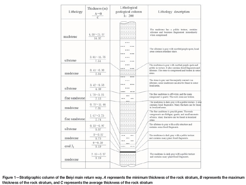
The Yuandian No. 2 coal mine in Anhui Province, China, has a mining area of 41.60 km2 (10.9-13.3 km from east to west and 1.3-5.3 km from south to north) with an estimated production capacity of 1.5 Mt/a. The depth of the Beiyi main return way is approximately 600 m. The tunnelling direction of the roadway is 31° north by east. The cross-section of the roadway is a semicircular arch. The walls are 1.5 m high, the arch is 2.7 m high, and the net width of the roadway is 5.4 m. The dip angle of the rock strata is 15-25°; the roadway passes through weak strata, such as mudstone, siltstone, and sandy mudstone (Figure 1). The lithology of the roof and floor is mudstone with a thickness of 7.5 m and 3.0 m respectively; the lithology of the two ribs is mudstone and siltstone. The strength and bearing capacity of the surrounding rock is very low.
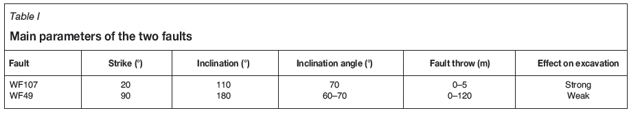
There are many faults in the Yuandian No. 2 coal mine, most of which strike northeast. In total, 107 geological sites were drilled to explore the characteristics and locations of the faults, and a total of 44 (39%) boreholes encountered faults. There are two faults in the area near the Beiyi main return way that affect the surrounding bedrock (Figure 2), creating fractures and secondary faults. The main parameters of the two faults are listed in Table I. Since the working face of the Beiyi main return way had to pass through fault WF107 (Figure 2), the effect on excavation was very marked. The other fault also had some effect on the excavation, but it was not as serious as that of fault WF107.
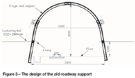
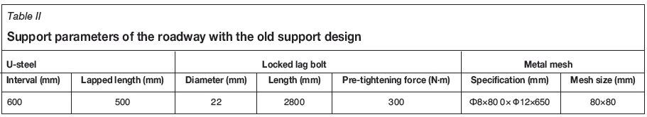
Primarily, U-steel support was used as the permanent support to maintain the roadway stability. A cross-section of the roadway and the supporting structure is shown in Figure 3. The support parameters are as follows (listed in Table II): U-steel lapped length 500 mm, and U-steel interval 600 mm. A layer of metal mesh is installed to fill the interval between the surrounding rock and the U-type steel, with a mesh specification of 08x800 χ 012x650 and a mesh size of 80 χ 80 mm. The thickness of the shotcrete between the U-steel supports is 150 mm, and the strength of the sprayed concrete is 20 MPa. Locked lag bolts (Figure 3) with a diameter of 22 mm and a length of 2800 mm were installed in the two ribs approximately 1200 mm above the floor. They were used to apply a pre-tightening force to keep the U-steel support in close contact with the surrounding rock.
Although the load-bearing capacity of the support was very high, macroscopic deformation and failure of the main roadway occurred within a week, especially in the two ribs and floor. In the two ribs, some locked lag bolts were pulled out or broken within two weeks after excavation (Figure 4a), and severe distortion of the U-steel support (Figure 4b) and falling of the sprayed concrete were prevalent in the roadway after one month. Timber props with a diameter of approximately 300 mm were set up to help mitigate the substantial deformation of the roadway (Figure 4d). The roadway floor heave (Figure 4c) was so serious that the concrete ditch was broken several times and was replaced with a steel tank. The results suggest that the traditional U-steel support design could not control the deformation of the roadway effectively under high stress. The roadway with this support required repair and the daily procedures of transport, ventilation, and safe production could not be guaranteed, therefore the costs of the production increased significantly.

Failure mechanics of the main return way
Physical and mechanical characteristics of surrounding rock
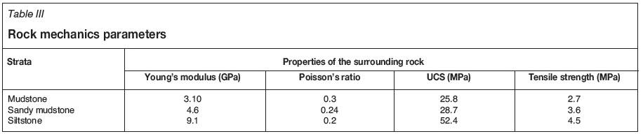
The surrounding rock is primarily mudstone, sandy mudstone, and siltstone. The roof and the two ribs consist of mudstone and siltstone with localized fine sandstone, while the floor is mainly siltstone and mudstone. Most of the surrounding strata are soft rock affected by faults and high tectonic stresses. With widespread development of fractures and fissures in the surrounding rock, the rock mass strength is very low. Lithological samples were collected from the surrounding rock of the Beiyi main return way, and conventional physical and mechanical tests (uniaxial compression testing, triaxial compression experiments, and Brazil disk split test) were conducted with an MTS 815.02 rock servohydraulic machine. The test results are shown in Table III. The mudstone and the sandy mudstone were typical soft rock, with a uniaxial compressive strength of 25.8 MPa and 28.7 MPa, respectively. The uniaxial compressive strength of the siltstone was about 52.4 MPa. Absorption of water reduced the strength of the rocks significantly, especially the mudstone. Uniaxial compression testing of the saturated mudstone indicated (Figure 5) that the UCS and modulus were reduced by 72.4% and 76% respectively, compared with the original samples.

During excavation, the mudstone exhibited obvious weakening and swelling after contact with water. Zhou and He (2008) pointed out that montmorillonite is extremely sensitive to water, especially Na-montmorillonite, which can undergo a volume expansion of 600-1000%. Li et al. (2007, 2010) investigated the deformation characteristic of mudstone from the Guhanshan mine, and the results indicated that the strain of the saturated mudstone was 7-8 times larger than that of the original sample. Erguler and Ulusay (2009) also concluded that the clay-rich rocks can expand, undergoing a dramatic reduction of the UCS, average modulus, and tensile strength (more than 90%) after absorbing water.
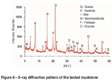
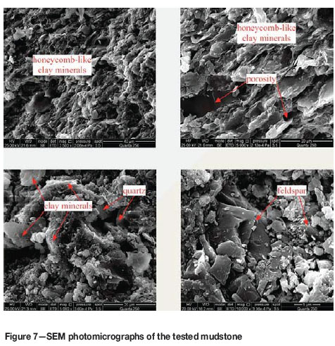
The mudstone collected from the Beiyi main return way was analysed using X-ray diffraction. The analysis (Figure 6) indicated that the mudstone is composed of quartz, feldspar, and clay minerals (including kaoline, illite, and montmorillonite). The content of clay minerals, which are very sensitive to environmental factors, is greater than 39%. Using scanning electron microscopy (SEM) techniques to observe the micromorphology and composition of the roof mudstone, we found that the mudstone is relatively unconsolidated and has a well-developed porosity. The hard skeleton grains, such as quartz and feldspar, are enclosed in the clay minerals. The single flaky crystals of minerals are distributed in a non-uniform, honeycomb-like pattern (Figure 7). This porous and loose microstructure could allow the mudstone to absorb water from the air, fractures in the rock mass, and construction process more easily, which would have an adverse effect on the long-term stability of the surrounding rock of the roadway. The Beiyi main return way was exposed to air after excavation, and this accelerated deformation and fracturing.
In situ stresses
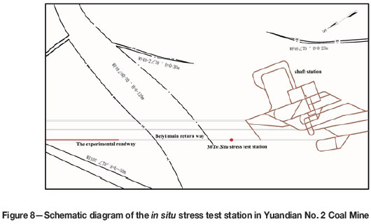
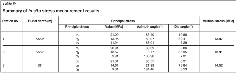
Three stress test stations are situated according to the geological and engineering conditions, but only the no. 3 station is close to the Beiyi main return way. A schematic diagram of the location of the no. 3 test site is shown in Figure 8. The principal stresses and their directions were determined, and are listed in Table IV. The test results showed that the maximum principal stress was approximately 21 MPa, the direction horizontal, and the azimuth angle between 83° and 86°. The tunnelling direction of the Beiyi main return way is 31° NE, resulting in an angle of approximately 52° between the tunnelling direction and the maximum principal stress direction. The current theoretical research and practical results (Zhao etal., 2015) show that the roadway stability would be affected by the tectonic stress, the influence being greater if the angle between the tunnelling and tectonic stress directions exceeds 45°. The minimum principal stress was approximately 10 MPa, with a dip angle and azimuth of approximately 7° and 184°, respectively. The vertical principal stress was approximately 14 MPa. The ratio between the maximum principal stress and vertical principal stress was 1.51, which indicated that the mining activities of the Yuandian no. 2 coal mine were affected by the tectonic stress.
Fracture characteristics of the surrounding rock
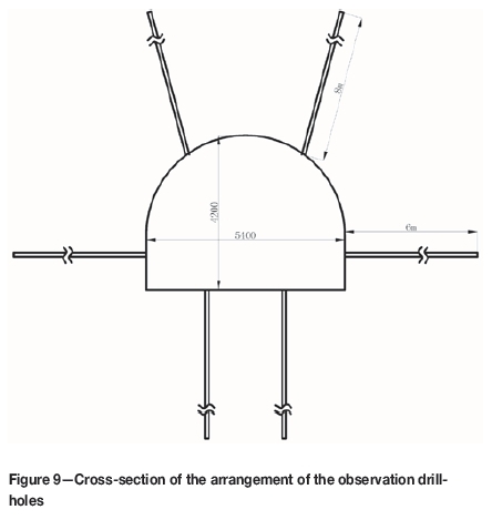
The fracture development characteristics of the surrounding rock have an important effect on the stability of the roadway. The failure characteristics of the surrounding rock were investigated with an intelligent drill-hole optical imager. The rock surrounding the main roadway can be classified into intact, initial fissure, mining-induced fracture, and rupture zones based on the development of the fractures. After the old support system was damaged, two monitoring sections were arranged in the Beiyi main return way to detect fracture development. Each cross-section included six observation drill-holes (Figure 9) - two in the roof, two in the floor, and two in the ribs. The observation drill-holes were 28 mm in diameter, and the maximum depth was 6.0-8.0 m. The observation results are shown in Figure 10.

As can be seen from Figure 10, the rocks surrounding the roadway consist of mudstone, sandy mudstone, and siltstone. The rupture zones are all found in the shallow section of the roadway; the fracture depths of the rupture zone for roof, rib, and floor are 3.0 m, 1.7 m, and 1.0 m respectively. Between 2.0 and 4.0 m, there is a soft intercalated layer with a thickness of 1.2 m, consisting of mudstone containing abundant clay minerals. After absorbing water, the mudstone softened and expanded. Because of the wide range and short distance to the roof, the soft intercalated layer would seriously affect the long-term stability of the roadway. Many mining-induced fractures were generated after excavation, with maximum depths of 1.2 m in the roof, 1.6 m in the ribs, and 2.2 m in the floor. There were some initial fissures in deep surrounding rock, but they had little influence on the stability of the roadway.
The design of yielding bolt - grouting support
The yielding grouting bolt and its mechanical characteristics
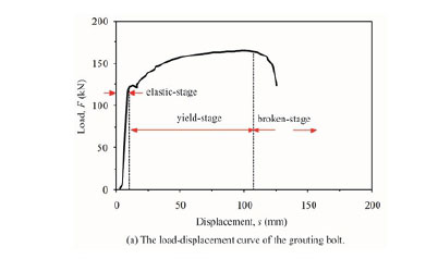
The main support material used in this yielding bolt -grouting design is the yielding grouting bolt. comprising a rod, pallet, metal gasket, plastic gasket, nut, and yielding tube (Figure 11b). There are many air-holes distributed on the hollow rod for the grout permeating into the rock fractures. Bolt pull-out tests were conducted and the results are shown in Figure 12. The load-displacement curve of the grouting bolt (Figure 12a) can be divided into three stages: (a) elastic stage, (b) yield stage, and (c) broken stage. The length of the yield stage accounts for 86.4% of the total deformation. After installation, the working condition of the grouting bolt was generally in this stage until the grout permeated into the surrounding rock. However, in high stress conditions, the deformation rate was high and the working condition of the grouting bolt always proceeded to the broken stage before grouting. Compared with the grouting bolt, a new yield stage was added to the load-displacement curve of the yielding grouting bolt before the rod yielded (Figure 12b). The length of the first yield stage can be varied by changing the structural features of the yielding tube. The existence of the first yield stage ensures that the working condition of the yielding grouting bolt is in the second yield stage and protects the yielding bolt - grouting support system from damage. The yielding grouting cable anchor consists of a rubber grouting pipe, anchor cable locks, metal gasket, yielding tube, pallet, anchor cable rope body, and twist anchor head. Its mechanical characteristics are similar to those of the yielding grouting bolt.


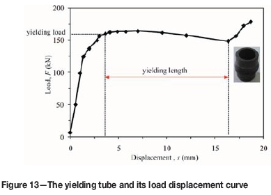
Compared with the traditional grouting bolt, the most obvious characteristic of the yielding grouting bolt is that a yielding tube is added to the bolt tail. A typical load-displacement curve of a yielding tube is shown in Figure 13. The load-displacement curve can be divided into three stages (Lu, Wang, and Zhang, 2011): elastic stage, yield stage, and plastic stage. The mechanical characteristics of the yielding tube mainly refer to the yielding load and yielding length. The load at the beginning of the yield stage is called the yielding load, and the length of the yield stage represents the yielding length.
Mechanics of yielding bolt - grouting support
Because of the intense deformation and failure of the surrounding rock, the stability of the Beiyi main return way could not be ensured by traditional support technology. Therefore, the yielding bolt - grouting support technology, which combines yielding grouting bolts (cable anchors) with other supporting structures, was proposed to stabilize the roadway. The mechanics of yielding bolt - grouting support can be interpreted with reference to five aspects.
(1) Compared with the traditional support system, the yielding bolt-grouting support can extend the maximum deformation that the support structure can accommodate. A schematic diagram of the traditional bolt - grouting support and yielding bolt - grouting support is shown in Figure 14. With the addition of a new yield stage, the maximum deformation of the yielding bolt - grouting support is much larger than that of the traditional support. Under high overburden and tectonic stresses, the deformation is large and the deformation rate is high in the earlier stages of the excavation. In the process of construction, there is about two weeks before grouting is prepared. With increasing deformation of the surrounding rock, the grouting bolt in the traditional support breaks while the yielding grouting bolt is still at the second yields tage with a flattened yielding tube. The yielding bolt -grouting support prevents the support system from proceeding to the broken stage before grouting is prepared.
(2) By changing the yielding length of the yielding tube, we can optimize the grouting time to obtain a better grouting effect. Lu et al. (2012) considered that there are two disadvantages if the grout permeates into the rock mass too early. One is that the fracture aperture is not large enough for the grout grains to permeate into it. Eklund and Stille (2008) conducted extensive laboratory tests and concluded that the grain size of the grout should be at least 2-3 times smaller than the fracture aperture; otherwise, the channels in the fractures would be obstructed by clogging of the cement grains. The other disadvantage is that the grouted fractures are still propagating and new fractures are continually generated under high stress after grouting. As a consequence, the grouted factures are re-broken and the control of the rock surrounding the roadway fails.
With the traditional support system, there is not enough extra deformation available to adjust the grouting time according to the fracture development in the surrounding rock. However, with the yielding bolt - grouting support the yielding length of the yielding tube can be changed in order to control the grouting time. In this way, the grouting effect and roadway stabilization have been improved. Moreover, the deformation of the yielding tube acts as an indicator to remind the miner to permeate the grout into the surrounding rock.
(3) With more effective grouting, the yielding bolt -grouting support can more effectively prevent the clay minerals from absorbing water, and reduce the adverse effects of swelling and weakening. Grouting fills the fractures and dramatically reduces the permeability of the surrounding rock (Eriksson and Stille, 2000; Yang, He, and Chen, 2001). Due to propagation of the grouted fractures and newly generated fractures, the grouting effect of the traditional support is not good enough to prevent the clay-rich rock from absorbing water. With excellent grouting quality obtained with the yielding bolt -grouting support, the rock permeability is much lower, and the clay-rich rock has less opportunity to contact water. Therefore, the yielding bolt - grouting support can more effectively prevent the surrounding rock from weakening and swelling due to contact with water.
(4) Compared with the traditional support system, the concentrated stresses caused by the excavation are transferred to the deeper surrounding rock and the degree of stress concentration is much less. Previous studies showed that the concentrated stress will be generated in the shallow surrounding rock of the roadway after excavation, and will break the rock mass and reduce the bearing capacity. The concentrated stress will then move into the deeper surrounding rock (Fahimifar and Hedayat, 2010; Zhang, Zhao, and Meng, 2013). For the traditional bolt - grouting support, as the maximum deformation of the support system is limited, the degree of fracture development is low and the stress is concentrated in the shallow surrounding rock. Assuming that the concentrated stress is X0q (q is the in situ stress, λ0is the stress concentration coefficient), the stress distribution is simplified as in Figure 14a. Because the concentrated stress is still in the shallow surrounding rock, the secondary damage would occur in the grout-filled cracks under the high concentrated stress after grouting. However, compared with the traditional bolt - grouting support, the degree of fracture development is much higher in the shallow surrounding rock under the yielding bolt - grouting support before grouting. The bearing capacity of the shallow surrounding rock declines and the stress has to transfer into deeper surrounding rock. As a result, the concentrated stress declines to l'0q (1< λ0 0< λ') (Figure 14b) and its location moves into deeper surrounding rock.
(5) With the better grouting effect, the bearing capacity of the rock mass is much higher than under traditional support. As one of the main active support technologies, grouting can fill the cracks, improve the surrounding rock strength, and enhance the resistance to deformation (Kikuchi et al., 1997; Varol and Dalgiç, 2006; Nikbakhtan and Osanloo, 2009). However, the grouting effect was not always satisfactory with the traditional grouting support, which would directly affect the stability of the roadway after grouting. With better grouting quality, the fractures in the surrounding rock under yielding bolt grouting support are filled with grout. After grout consolidation, the broken rock is bonded and the strength and stiffness of are improved, thus the bearing capacity of the surrounding rock is greatly increased.

The new support design
After investigating the deformation and failure mechanics of the Beiyi main return way, we found that the reasons for the roadway instability could be summarized as follows:
(a) Soft and weak surrounding rock due to the widespread development of fractures
(b) Weakening and swelling due to the effects of water
(c) High tectonic and overburden stress
(d) Inappropriate support.
Bolt grouting support is an ideal choice, because grouting can seal fractures, bond the broken rock, improve the strength of the surrounding rock, and enhance the resistance to deformation (Kikuchi et al., 1997; Varol and Dalgiç, 2006; Nikbakhtan and Osanloo, 2009). However, the deformation and deformation rate are very large during the early stage of excavation, the support system may be damaged before grouting can be completed, and the grouted fractures would be broken again. To solve this problem, the yielding bolt -grouting support method is proposed, with the new support design shown in Figure 15. The support parameters are as follows.
(1) Since the yielding grouting bolts (anchors) have been added to the yielding bolt-grouting support scheme, the density of U-steel supports can be reduced. The U-steel interval was extended from 600 mm to 700 mm to reduce the labour requirements and support costs.
(2) Yielding grouting bolt: according to the fracture characteristics analysis, the maximum development depth of the mining-induced fractures is 2.2 m, and the minimal bond-anchorage length is at least 0.3 m. Therefore, the length of the yielding grouting bolt is 2.6 m and the specification of the yielding bolt-grouting was 025 χ 2600 mm. Since the interval between the U-steel supports is extended to 700 mm, the bolts are added to supply the support load. The spacing between the bolts along the roadway axis is 1.4 m, and the spacing radially along the roadway is 1.5 m. Eleven yielding grouting bolts were installed on each cross-section, with five in the roof, four in the two ribs, and two in the floor. All the bolts should be under pre-tension. Considering the yielding load of the yielding grouting bolt and construction conditions, the pre-tension load is 70 kN.
(3) Yielding grouting cable anchor: the maximum development depth of the fractures is 6.5 m in the roof, and there is a soft intercalated layer between 4.9 and 5.1 m. To ensure that the cable anchors are bonded into the intact rock, the length of the cable anchors is chosen as 7.0 m. The spacing between the cable anchors along the roadway axis is 2.1 m, and the specification is 031.5 mm χ 7.0 m.
(4) Inverted arch: the floor of the roadway was broken under the tectonic stress, therefore the inverted arch was adopted to control the floor heave. The roadway floor was excavated 0.5 m deeper than necessary and then filled with waste rock and concrete. The grouting bolts, with a specification of 025 mm χ 2.6 m, were then installed. The spacing between the bolts along the roadway axis is 2.1 m, and 2.0 m radially along the roadway.
(5) Grouting reinforcement: the grout used in the support is no. 525 Portland cement with a little additive. The additive increases the stability, fluidity, and expansibility to improve the curing rate and the strength of the anchorage body. The water to cement ratio is between 0.7:1 and 1:1, the grouting pressure of the yielding grouting cable anchor is 4.0 to 6.0 MPa, and the grouting time is 600 to 800 seconds. The grouting pressure of the yielding grouting bolt was 2.0 to 3.0 MPa, and the grouting time was 250 to 400 seconds.

Field experiment and monitoring
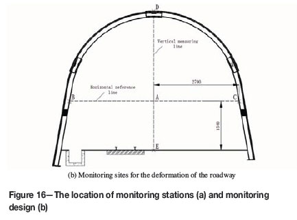
A field experiment was conducted in the mine to test the effectiveness of the new ' 'yielding bolt - grouting' design and compare it to the old design. A 100 m long section of the Beiyi main return way was chosen to compare the two support designs. Half of the roadway was supported with the old design, and the other half by the new yielding bolt -grouting design. Four monitoring stations were arranged to measure the deformation of the roadway. Two stations (stations I and II) were in the experimental roadway with new support design, and the other two (stations III and IV) were in the section with old design. The monitoring locations in both the new and old designs were separated by 20 m as shown in Figure 16a. The deformation of the surrounding rock was monitored by two extensometers installed in each of the four monitoring sections. One extensometer was installed in the two ribs of the roadway between points B and C, and the other between points D and Point E as shown in Figure 16b. BC is the horizontal measuring line, and DE the vertical measuring line. 'A' is the intersection point of segments BC and DE. A decrease of segment BC indicates the inward displacement of the two ribs, while a decrease of segment AD represents displacement of the roof, and a decrease of AE indicates displacement of the floor. The technical specifications of the extensometers were: measurement range 0 to 1000 mm, and accuracy 0.2 mm.

The extensometers were installed immediately after the roadway support structure was completed, and the data from the extensometers was read every five days. All the data was collected and plotted to analyse the deformation of the roadway surrounding rock. The grout was injected approximately 20 days after completion of the roadway support. The deformation of the surrounding rock was monitored for 65 days, and the results are shown in Figure 17.
It is clear that the displacements of the roadway with the new support design are much smaller than with the old support design. In the first 20 days after excavation, the maximum displacements of roof, floor, and left rib with the yielding bolt - grouting were 92.4 mm, 109.2 mm, and 63.6 mm respectively, compared with 118.6 mm, 169.2 mm, and 119.1 mm with the old support design. Although the displacements for the yielding bolt - grouting support are smaller, there is no dramatic difference between the two support schemes before grouting. This is because the support load densities (the support load per square metre) of the two support schemes are almost the same. After grouting, this situation changes. The displacements of the roof, floor, and rib at the monitoring station I (in the old support design section) were 254.4 mm, 376.8 mm, and 279.8 mm, respectively, after 65 days. Similar results can be seen at station II. The resulting instability of the roadway necessitated repair work to ensure safety and continued production. With the new support design, the maximum displacements of roof, floor and rib were 149 mm, 165.4 mm, and 98.8 mm, respectively. Compared with the old support design, the new support design reduced the deformations of roof, floor, and rib by 41.4%, 56.1%, and 64.7% respectively.
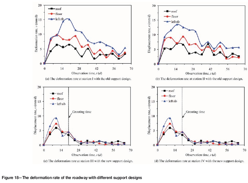
Since the support load density (the support load per square metre) of the yielding bolt - grouting support is only slightly larger than that of the old support design, the deformation rates of the surrounding rocks are very high for both designs before grouting (Figure 18). However, the displacement rates of the roadway with the yielding bolt -grouting support dropped sharply after grouting, while the deformation continued to increase rapidly in the old support design section. The deformation rate of the left rib in station II decreased by 29.6% (from 15.12 to 10.64 mm/d) in ten days after grouting, while the deformation rate in station IV decreased by 80.5% (from 4.52 to 0.88 mm/d) in the same period. After inspection of the support systems we found that some U-steel supports had been twisted and 17 bolts had broken in the old support design section, while no damage was found in the yielding bolt - grouting support system. After the support elements were damaged, the bearing capacity of the old support system would drop rapidly, and this is the most important reason why the old design could not control the deformation and failure of the Beiyi main return way. After 65 days, the maximum displacements of roof, floor, and rib were 3.24 mm/d, 3.68 mm/d, and 5.44 mm/d, respectively, which led to considerable deformation. With the new support design, all the deformation rates of the surrounding rock dropped to less than 1.0 mm/d. Therefore, the deformation of the Beiyi main return way was controlled efficiently by the yielding bolt - grouting support, as shown in Figure 19. This significantly reduces roadway maintenance and repair costs. Compared to the old support system, the yielding bolt-grouting support design could reduce support costs by 985.2 Yuan (US$159.60) per metre of roadway. The full length of the Beiyi main return way is 1285 m, so 1 265 982 Yuan US$205 089 would be saved by this design. The yielding bolt - grouting support therefore offers considerable economic and as well as technical benefits.

Conclusions
A case study on the effect of the yielding bolt - grouting support design on the stability of a roadway in soft rock was conducted in an underground coal mine in Huaibei Province, China. The surrounding rock was very weak and contained an abundance of clay minerals, which were vulnerable to weathering. The roadway experienced substantial deformation with the old support design, therefore a new support design was proposed.
The deformation and failure of the Beiyi main return way can be attributed to four reasons: (1) abundant clay minerals in the surrounding rock, (2) high tectonic stress, (3) widespread development of fractures in the surrounding rock, (4) unscientific support design.
Compared with traditional support, the mechanics of the yielding bolt - grouting support system were analysed and interpreted from five aspects:
(1) With larger maximum deformation of the support structure being accommodated, the yielding bolt -grouting support can prevent the support system from proceeding to the broken stage before grouting
(2) Grouting time can be optimized to obtain a better grouting effect
(3) Clay minerals are prevented from absorbing water and the effects of swelling and weakening are reduced
(4) The degree of stress concentration is reduced and the concentrated stresses are transferred into deeper surrounding rock
(5) The bearing capacity and resistance to deformation of the surrounding rock are improved.
A field experiment was performed in the mine along a 100 m section of roadway. The monitoring results indicated that the new support design could significantly improve the stability of the Beiyi main return way. Compared to the old support system, the yielding bolt - grouting support design significantly reduces roadway maintenance and repair costs. The new support system has great prospects for broader application.
Acknowledgments
This work was supported by the National Natural Science Foundation of China (Project No. 51274191 and 51204159), the National Basic Research Program of China (Project No. 2014CB046905), the National Natural Science Foundation of China (Project No. 51708245), the Natural Science Foundation for Colleges, Universities in Jiangsu Province (Project No. 17KJB130003 and 17KJA560001), and the Doctoral Fund of the Ministry of Education of China (Project No. 20130095110018). The authors thank the anonymous referees for their careful reading of this paper and valuable suggestions.
The authors declare that there are no conflicts of interest regarding the publication of this paper.
References
Eklund, D. and Stille, H. 2008. Penetrability due to filtration tendency of cement-based grouts. Tunnelling and Underground Space Technology, vol. 23, no. 4. pp. 389-398. [ Links ]
Erguler, Z.A. and Ulusay, R. 2009. Water-induced variations in mechanical properties of clay-bearing rocks. International Journal of Rock Mechanics and Mining Sciences, vol. 46, no. 2. pp. 355-370. [ Links ]
Eriksson, M., Stille H., and Andersson, J. 2000. Numerical calculations for prediction of grout spread with account for filtration and varying aperture. Tunnelling and Underground Space Technology, vol. 15, no. 4. pp. 353-364. [ Links ]
Fahimifar, A. and Hedayat, A.R. 2010. Elastoplastic analysis in conventional tunnelling excavation. Geotechnical Engineering, vol. 163, no. 1. pp. 37-45. [ Links ]
Gao, Y., Wang, B., Wang, J., Li, B., Xing, F., Wang, Z., and Jin, T. 2010. Test on structural property and application of concrete-filled steel tube support of deep mine and soft rock roadway. Chinese Journal of Rock Mechanics and Engineering, vol. 29, no. 1. pp. 2604-2609. [ Links ]
Guo. Z., Qian. L., and Wang. J. 2009. Coupled bolt-mesh-anchor-truss supporting technology and its engineering application to deep soft rock roadway. Chinese Journal of Rock Mechanics and Engineering, vol. 28, no. 2. pp. 3914-3919. [ Links ]
He, M. 2006. Rock mechanics and hazard control in deep mining engineering in China. Rock Mechanics In Underground Construction. Leung, C.F. and Zhou, Y. X. (eds.). World Scientific, London. pp. 29-46. [ Links ]
He, M. 2014. Progress and challenges of soft rock engineering in depth. Journal of China Coal Society, vol. 39, no. 8. pp. 1409--417. [ Links ]
Jiang, B., Wang, L., Lu, Y., Gu, S., and Sun, X. 2015. Failure mechanism analysis and support design for deep composite soft rock roadway: a case study of the Yangcheng coal mine in China. Shock and Vibration, vol. 2015. pp. 1-14. [ Links ]
Kang, Y., Liu, Q., and Xi, H. 2014. Numerical analysis of THM coupling of a deeply buried roadway passing through composite strata and dense faults in a coal mine. Bulletin of Engineering Geology and the Environment, vol. 73, no. 1. pp. 77-86. [ Links ]
Kikuchi, K., Igari, T., Mito, Y., and Utsuki, S. 1997. In situ experimental studies on improvement of rock masses by grouting treatment. international Journal of Rock Mechanics and Mining Sciences, vol. 34, no. 3-4. pp. 138.e1-138.e14. [ Links ]
Li, G., Dai, T., Lv, F., anD Yang J. 2007. Deformation mechanism of swelling rock and its grouting reinforcement techniques. Journal of Mining & Safety Engineering, vol. 24, no. 4. pp. 44-4448. [ Links ]
Li, G., Li, Z., and Dai, T. 2010. Mechanical test of swelling rock and prediction of roadway support parameters. Engineering Mechanics, vol. 27, no. 2. pp. 96-101. [ Links ]
Li, W., Li, S., Xuan, C., Wang, Q., and Wang, X. 2015. Mechanism and control of failure of rock roadway support in highly stressed soft rock. Chinese Journal of Rock Mechanics and Engineering, vol. 34, no. 9. pp. 1836-1848. [ Links ]
Lu, Y., Wang, L., Yang, F., Li, Y., and Chen, H. 2010. Post-peak strain softening mechanical properties of weak rock. Chinese Journal of Rock Mechanics and Engineering, vol. 29, no. 3. pp. 640-648. [ Links ]
Lu, Y., Wang, L., anD Zhang, B. 2011. An experimental study of a yielding support for roadways constructed in deep broken soft rock under high stress. Mining Science and Technology (China), vol. 21, no. 6. pp. 839-844. [ Links ]
Lu, Y., Wang, L., Zhang, B., andLi, Y. 2012. Optimization of bolt-grouting time for soft rock roadway. Rock & Soil Mechanics, vol. 33, no. 5. pp. 1395-1401. [ Links ]
Nikbakhtan. B. and Osanloo. M. 2009. Effect of grout pressure and grout flow on soil physical and mechanical properties in jet grouting operations. International Journal of Rock Mechanics and Mining Sciences, vol. 46, no. 3. pp. 498-505. [ Links ]
Shen, B. 2014. Coal mine roadway stability in soft rock: a case study. Rock Mechanics and Rock Engineering, vol. 47, no. 6. pp. 2225-2238. [ Links ]
Varol, A. and Dalgiç, S. 2006. Grouting applications in the Istanbul metro, Turkey. Tunnelling and Underground Space Technology, vol. 21, no. 6. pp. 602-612. [ Links ]
Wang, L., Lu, Y., Huang, Y., and Sun, H. 2016. Deep-shallow coupled bolt-grouting support technology for soft rock roadway in deep mine. Journal ofChina University ofMining & Technology, vol. 45, no. 1. pp. 11-18. [ Links ]
Wasantha, P.L.P. and Ranjith, P.G. 2014. Water-weakening behavior of Hawkesbury sandstone in brittle regime. Engineering Geology, vol. 178. pp. 91-101. [ Links ]
Yang, M., He, Y., and Chen, M. 2001. Law of grouting penetrating through fracture network of rock mass. Journal of Hydraulic Engineering, vol. 7. pp. 41-46. [ Links ]
Zhou, L. and He M. 2008. Study on mineralogical characteristics of high stress soft rock at depth of Nanshan Mine. Metal Mine, vol. 384, no. 6. pp. 73-76. [ Links ]
Zhang, X., Zhao, G., and Meng, X. 2013. Elastoplastic analysis of surrounding rock on circular roadway based on Drucker-Prager yield criterion. Journal of the China Coal Society, vol. 38, Supplement. pp. 30-37. [ Links ]
Zhao, W., Han, L., Zhang, Y., Zhao, Z., and Wang, G. 2015. Study on the influence of principal stress on the stability of surrounding rock in deep soft rock roadway. Journal ofMining and Safety Engineering, vol. 32, no. 3. pp. 504-510. [ Links ]
Paper received Jul. 2016
Revised paper received Aug. 2017

