


Services on Demand
Article
 English (pdf)
 Article in xml format
 Article references
Indicators

Related links
-
 Cited by Google
 -
 Similars in Google
Share

 Permalink
Journal of the Southern African Institute of Mining and Metallurgy
On-line version ISSN 2411-9717
Print version ISSN 2225-6253
J. S. Afr. Inst. Min. Metall. vol.118 n.1 Johannesburg Jan. 2018
http://dx.doi.org/10.17159/2411-9717/2018/v118n1a3
PAPERS OF GENERAL INTEREST
Ground control in mining steeply dipping coal seams by backfilling with waste rock
T. ZhaoI; Z. ZhangII; Y. YinI; Y. TanI; X. LiuII
IState Key Laboratory of Mining Disaster Prevention and Control, Shandong University of Science and Technology,Shandong, China
IIState Key Laboratory of Coal Mine Disaster Dynamics and Control, Chongqing University, China
SYNOPSIS
The mining of steeply dipping coal seams involves significant safety risks because of instability caused by the weak nature of surrounding rocks and their movement after excavation. Physical and numerical models were developed to determine an optimum backfill approach to ground control in steeply dipping coal seams. Physical modelling showed that for mining without backfill, the thickness of the largest roof collapse was approximately twice that of the mined seam, the movement of roof strata tended to be asymmetrical, and there was a relatively large empty zone in the upper gob area. For mining with backfill, roof conditions were significantly improved; only slight roof separation appeared 1.5 m above the mined seam. The largest cumulative displacements occurred 5-15 m from the first cut of mining. With backfill, the levels of mining-induced stress release and concentration were significantly reduced, and the vertical range of mining disturbance was shortened by 18%. Numerical modelling showed that floor strata mainly undergo nearly horizontal displacements, while roof strata mainly undergo vertical subsidence, both with and without backfill. The integrity of roof strata improved as the extent of backfill increased, and the range of displacement direction increased. The conclusions are confirmed by results from a field trial.
Keywords: Steeply dipping coal seam, backfill, ground control, strata mechanics, waste rock.
Introduction
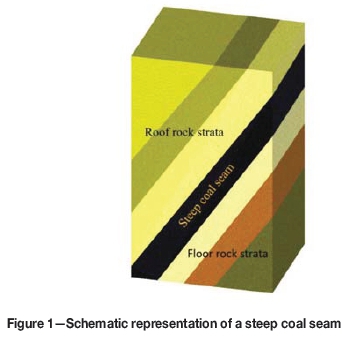
In the Chinese coal industry, a steep coal seam is defined as one that dips at an angle greater than 45° (Cao and Gou, 2011), as shown in Figure 1. In contrast to coal seams with little or no (flat) dip angle, mining production from steeply dipping seams is inherently low and the cost is relatively high. These factors hinder extraction from such seams in developed countries, such as the USA. In developing countries, however, mining of steeply dipping coal seams is rapidly growing because of high reserves available in such configurations, such as in western China and the Jharia coalfield in India. In China, steeply dipping coal seams comprise 15-20% of total coal reserves.
Underground mining of steep coal seams using current technologies presents significant safety risks: sliding movements cause instability in the working faces and the rock mass in and around such seams tends to be fragile due to impact of local geological structures such as faults and folds. Generally, fractures exist in the roof strata before mining; these fractures propagate and further coalesce with new fractures developed in the mining process, increasing the probability of roof collapse. Such roof failure can extend upwards as a consequence of the large inclination angle of the coal seam. To reduce deformation of the surrounding rock for ground control, backfill technology has been introduced in steep coal seam mining. In addition, backfill mining is also more environmentally friendly because less surface land is required to store mine tailings and dust or water contamination from surface storage of waste rock is reduced (Bian et al., 2012; Sui et al., 2015).
Wang et al. (2011) numerically determined that pillar strength increases with the extent of roadway backfill, regardless of the cohesive or non-cohesive nature of the backfill, especially for pillars of large height-to-width ratio. However, Kostecki and Spearing (2015) numerically found that use of a cohesive fill can improve the pillar strength by 10-40% with fill extent of 25% and 75%, while non-cohesive fill contributed little to pillar strength, indicating that the early bearing capacity of backfill should be considered in pillar design for weak roof conditions. Tesarik, Seymour, and Yanske (2009) investigated the long-term stability of a backfilled room-and-pillar test section in a metal mine (where the roof and floor strata usually consist of hard rocks) and found that backfill helps to maintain roof strata integrity and the pillar strength for long-term stability. All of these studies were, however, carried out in flat or gently inclined, rather than steep, strata. For steep coal seam mining, Kulakov (1995a, 1995b) argued that the supporting pressure and roof deformation depend mainly on the mining depth, thickness of the seam, and roof parameters, such as roof span and thickness of the immediate roof; however, no ground control by backfilling was incorporated. More recently, Feng et al. (2017) developed a roof thin plate model to evaluate the effectiveness of solid-backfill in ground control. Mo et al. (2017) numerically investigated the effect of backfilling on coal pillar strength.
For backfilled mining, dry waste rock, cemented waste rock, hydraulic sand fill, and paste backfills have been used. This study focused on backfill with dry waste rock because the cost is relatively low and gravity-driven emplacement of the backfill material can be used for steeply dipping stopes. Extensive prior studies have been conducted on hydraulic and cement fills, either with respect to geotechnical evaluation of backfill or stress development in backfilled stopes (Klein and Simon, 2006; Sivakugan et al., 2006). In a laboratory study, Klein and Simon (2006) reported that strength development of cemented paste backfill was closely related to its composition, noting that polycarboxylated acrylic acid-based polymer was especially favoured for its rapid stiffness development. Fall et al. (2010) and Walske et al. (2016) experimentally found that curing temperature had a significant influence on the mechanical properties of cement paste backfill; however, this influence changed with content of the components and curing time. Using an ultrasonic wave measurement technique, Galaa et al. (2011) investigated the effect of saturation on stiffness of cemented backfill and found that the binder content had a more significant impact on stiffness in submerged cemented paste backfill than in air-dried backfills. Fahey, Helinski, and Fourie (2011) confirmed that the strength of cemented backfill increased with applied effective stress during curing; this improvement became more pronounced if effective stress was applied at a higher rate during the early stages of hydration. This conclusion is consistent with the experimental study of Yilmaz, Belem, and Benzaazoua (2014). Mishra and Karanam (2006) used fly ash to replace widely used river sand and mill tailings as backfill material and found that its compressive strength increased significantly after 56 days of curing. Sivakugan et al. (2006) experimentally evaluated the geotechnical properties of a hydraulic fill that is widely used in Australia.
With respect to the stress developed in backfilled stopes, Li and Aubertin (2009) analysed the influence of stope geometry, backfill properties, and filling sequence on the stress state of inclined backfilled stopes using FLAC2D software, and found that the stope inclination angle had a significant impact on vertical stress but relatively little effect on horizontal stress. Fahey, Helinski, and Fourie (2009) numerically found that horizontal stress differed within a backfilled stope due to the arching effect. On a field scale, Helinski, Fahey, and Fourie (2011) monitored the vertical stress and pore pressure in a stope backfilled with cement paste and observed a significant arching effect on the vertical stress. Mkadmi, Aubertin, and Li (2013) numerically illustrated that drainage can effectively reduce pore pressure within backfill and hence increase the interactive frictional stress between the backfill and rock walls. Doherty et al. (2015) found that the filling and resting schedule was a dominant factor influencing total stress and pore pressure development in a stope with cemented paste backfill.
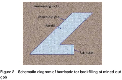
Regarding the barricade for the backfilling of mined-out gob (Figure 2), field measurement showed that the barricade tends to be stable in large stopes with a high binder content in cemented paste backfill, indicating the significance of the early development of bearing capacity in backfill (Thompson, Bawden, and Grabinsky, 2012). Hughes et al. (2010) introduced a novel destructive fill fence test to evaluate the ultimate capacity of a barricade. To ensure stability, an optimal position exists for a barricade to bear a low backfill load (Li and Aubertin, 2009, 2011). Fall and Nasir (2010) investigated the mechanical behaviour of the interface between cemented backfill and the retaining wall using a direct shear test, finding that it followed the Mohr-Coulomb criterion and its frictional angle increased with curing time.
Prior to extraction, steeply dipping coal seams generally experienced violent tectonic movements over geological time. As a result, the surrounding rock strata are usually weaker than in the case of flat coal seams. For this reason, the interaction between backfill and the surrounding rock mass can be complex compared to that of flat coal seams. It is therefore important to study the ground control mechanism of backfill in steeply dipping coal seam mining. This is also of great significance for promoting the utilization rate of coal mine waste rock in China.
To address the issues discussed above, physical and numerical simulations were employed to investigate the behaviour of rock strata and the ground control mechanism of backfill in steep coal seam mining. Physical modelling with equivalent materials is usually used to investigate deformation and failure of engineering prototypes (Jeremic, 1985); however, its repeatability is poor. Therefore, a physical model was developed to elucidate the mechanism by which backfilled waste rock resists roof cave-in, while numerical modelling was introduced to study the effect of the extent of the backfill on ground control. A field trial was then conducted to examine ground control performance of backfill in a steeply dipping coal seam. Such a study is essential to the successful application of the backfill method in steep coal seam mining.
Experimental methods
Physical modelling with equivalent materials has been used in mining and geotechnical engineering to provide a basic understanding of the mechanical behaviour of engineering prototypes (Jeremic, 1985). A physical model was developed to simulate an engineering prototype according to the theory of similarity (Jeremic, 1985), where instrumentation can be mounted to monitor the deformation and stress variations and the characteristics of the prototype were inferred from the similarity ratio. Note that the concept of equivalent materials involves inherent limitations. For example, physical modelling in the case of stress analysis might encounter difficulties due to the differences in physical and strength properties of the model and prototype materials (Jeremic, 1985). Furthermore, even physical models developed with the same rule may yield results that indicate a greater or lesser difference in behaviour of strata mechanics due to the operational process during model preparation and implementation. Considering that the rock strata are invisible and mined-out gob is inaccessible in practical mining activities, field monitoring is usually costly. The physical modelling approach with the concept of equivalent materials, on the other hand, is relatively rapid to implement and of low cost.
Development of the physical model
The physical model addressed similarities of scale, geometry, loading, and physical and mechanical properties.
For geometric similarity, the prototype dimensions were shrunk to develop the physical model at the same ratio:
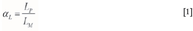
where olLis the similarity ratio of dimension L, and subscripts P and M denote the prototype and physical model, respectively.
With regard to the physical similarity, applied stress and specific mass were considered as:
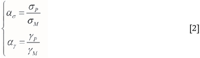
where α σ and α γ are the similarity ratios of stress σ and specific mass γ of the material, respectively. The subscript P represents the parameter of engineering prototype while the subscript M represents the parameter of physical model. The initial conditions of the physical model were similar to those of the prototype, including the strata distribution and mechanical properties. The boundary conditions of the physical model were consistent with the actual boundaries. To simplify, a plane model was considered with respect to how plane strain mode is accommodated in a field situation. Deformation normal to the model plane was restricted during experiments to ensure validity.
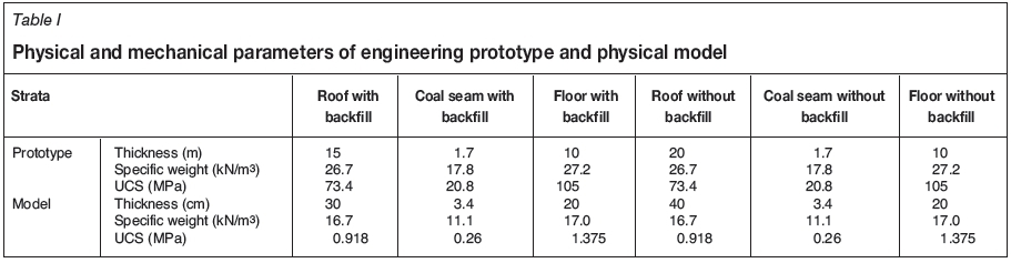
The prototype for the steeply dipping coal seam was the no. 5 coal seam in Datai mine, Beijing, China. The dip of this seam varies from 60° to 76°, with an average of 70°, and its thickness ranges from 1.23 m to 1.90 m, with an average of 1.70 m. The geometrical parameters of the roof, coal seam, and floor strata are listed in Table I.
The similarity ratio of dimension aLwas set to 50, and hence the corresponding thickness of the coal seam in the physical model was 3.40 cm according to Equation [1]. The similarity ratio for specific mass aywas set to 1.6, while the similarity ratio for stress α σ was set to 80.
To compare the effects of mining a steeply dipping coal seam with and without backfill, two seams were established in the physical model, as schematically shown in Figure 3a, one of which was extracted and backfilled and the other extracted without backfill. The purpose of establishing these two seams in a single physical model was to reduce the experimental error introduced by the process of constructing a new model, and hence improve the reliability of the results. The interval between these two seams was designed as 60 cm, which represented 30 m in practice. According to the closed-form solution for a circular excavation, the impact zone of the excavation is around five times the excavation radius and the stresses recover to far-field stresses beyond this zone (Brady and Brown, 2004). It should be noted that this is only an estimation based on a circular excavation in an infinite half-plane. In this physical model, the thickness of two coal seams was 1.70 m and the vertical distance between them was set as 30 m to avoid any interactions. The dip angle of the two seams was set as 70°. The basic physical and mechanical parameters of the coal and rock mass were obtained by shrinking the engineering prototype according to the relevant similarity ratios, as summarized in Table I.


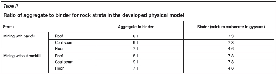
The composition of the equivalent materials is crucial for physical modelling in mining and geotechnical engineering. It should not only reflect similarity of physical and mechanical properties between the engineering prototype and the model, but also ensure stability of the physical model in case of experimental failure. In this study, fine sand grains (< 0.42 mm) were selected as the aggregate material, and gypsum and calcium carbonate were used as binders to simulate the roof and floor strata. For the coal seams, coal ground to less than 0.50 mm diameter was used as the aggregate material, and gypsum and calcium carbonate were again used as the binder material. These materials were selected because their failure mode tends to be brittle after construction. Tap water was used to mixed the aggregate and binder materials. The ratios of aggregate, binder, and water affect the mechanical parameters of the physical model. Following the calculated mechanical parameters shown in Table I, the ratio between aggregate and binder was determined for different rock strata, as summarized in Table II. The mass ratio of water to aggregate plus binder was kept strictly to 1:9, as extra water would increase the porosity of the physical model after curing.
The physical model, which was constructed on a laboratory test bench, had a length of 190 cm, a height of 140 cm, and a width of 22 cm. The physical model prior to any excavation is shown in Figure 3.
Instrumentation
Deformation and stress variation during the mining process were monitored. The plane surface of the physical model was first marked with two sets of parallel ink lines, one along the dip direction of the coal seam and the other along the horizontal direction. A mesh network with grid size of 5 cm χ 5 cm was developed for convenience of instrumentation mounting, as shown in Figure 3b. Displacement calibration papers were pinned at some grid nodes to identify the positions at which deformation was monitored during mining (Figure 3).
For the case of mining without backfill, three displacement monitoring lines were set in the roof strata and one in the floor strata. The interval between two adjacent monitoring lines in the roof strata was 10 cm and the first displacement line was located 5 cm above the seam. Nineteen measurement points were set in each monitoring line at 5 cm intervals. In addition, a horizontal displacement monitoring line was set near the top boundary of the model, with nine monitoring points at 5 cm intervals. For the case of mining with backfill, three displacement monitoring lines were set in the roof strata and the detailed layout was the same as that without backfill. A horizontal displacement monitoring line was also set near the top boundary of the physical model, with six monitoring points at 5 cm intervals.
Pressure transducers were installed in the roof strata to monitor stress changes during mining. Stress monitoring lines, located 5 cm above the coal seam, were established for both cases. Each line consisted of eleven monitoring points at 10 cm intervals. The detailed layout of the stress monitoring points is shown in Figure 3b.
During an experiment, the mining sequence was from top to bottom and the initial excavation (first cut of mining) started 30 cm from the top boundary. The mining distance for each step along the vertical direction was 5 cm, representing 2.5 m in practice, and the time interval between subsequent steps was 2 hours. In total, the mining excavation was conducted up to 80 cm along the vertical direction, representing 40 m in the real mining environment. In the case of mining without backfill, no treatment of the mined-out void (gob) after excavation was conducted, allowing for free roof collapse. In the case of backfilled mining, foam particles were used to backfill the gob after each mining step. Transparent plexiglass was used as a barrier to prevent loss of foam particles on the two lateral sides of the model.
Development of numerical model
The particulate discrete element modelling (DEM) method was chosen for two reasons. Firstly, with particulate DEM, the particle-scale mechanisms underlying the complex overall material response can be numerically analysed. Secondly, particulate DEM allows analysis of the mechanisms involved in large displacement problems, such as massive detachment of particles (O'Sullivan, 2011). These two issues cannot be solved with a continuum approach and traditional DEM methods, such as the commercial codes FLAC and UDEC. The numerical model, generated using PFC2D, was 40 m long and 50 m high, as shown in Figure 4.
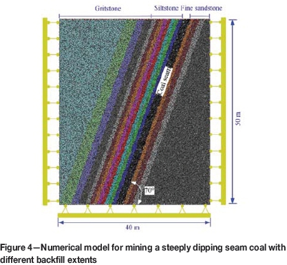
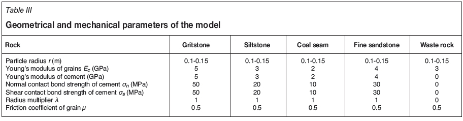
In the numerical model, the thickness of the coal seam was 2 m with a dip angle of 70°. The roof strata consisted of siltstone and gritstone and the floor was fine sandstone. The geometrical parameters of the model are given in Table III. Roller conditions were applied on the lateral and bottom model boundaries; horizontal displacement was constrained by the lateral boundary, and vertical and horizontal displacements were constrained at the bottom boundary. A vertical compressive stress of 20 MPa was applied at the top boundary to simulate the overlying burden of rock strata. Note that the model geometrical dimensions, 40 m in length and 50 m in height, have a certain effect on the numerical results at the model boundary. However, this numerical study is mainly to investigate the effects of different backfill extents on the deformation of roof and floor strata, rather than at the model boundary. Therefore, such a limitation of the model dimension on the boundary result was not considered here.
The bonded-particle model (BPM) was used to simulate the rock strata and coal seam (Potyondy and Cundall, 2004). In a BPM model, the grain micro-properties are characterized by Young's modulus of the grains (Ec), the ratio of normal to shear stiffness of the grains (kn/ks), and the grain friction coefficient (μ); cement micro-properties are characterized by the radius multiplier used to set the parallel bond radii (λ), Young's modulus of the cement (Ēc), ratio of normal to shear stiffness of the cement (kn/ks), normal contact bond strength of the cement (σ η ), and the shear contact bond strength of the cement (σ s). According to Potyondy and Cundall (2004), the grain and cement moduli are related to their normal stiffnesses:
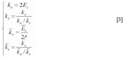
where  is the average radius of two contact grains. Considering the no-bonding characteristics of backfilled waste rock, its normal and shear contact bond strengths were set to zero to mimic the fact that there were no cohesive forces among the particles.
The Young's modulus of particle assembly, Ec, was taken from the laboratory test results. The normal contact bond strength of cement σηis derived according to the following relationship (Kulatilake et al., 2001):

where σt is tensile strength measured from the laboratory test. The shear contact bond strength σt was taken to be equal to the normal contact bond strength of cement σ η .
In BPM, the parameters of friction coefficient and spring stiffnesses are not directly linked to any physical measurement. Their sensitivity to the numerical modelling of particulate discrete element method is reviewed by O'Sullivan (2011). Referring to Kulatilake et al. (2001) and the PFC2D manual (Itasca, 2008), the ratios of normal to shear stiffness of the grains and cement were both taken as 2.5 and the radius multiplier of cement was set as unity. The mechanical parameters of the numerical model are given in Table III.
Mining was conducted from top to bottom with 2.5 m in each mining cut. Ten cuts were conducted in total. Mining processes without backfill and with 50%, 70%, and 90% backfill were simulated.
Results and discussion
Characteristics of strata mechanics
Failure ofroofstrata
During the entire mining process described above, there were four instances of major roof collapse for mining without backfill, while only slight separation occurred for mining with backfill.
Figure 5 shows the evolution of the state of the roof strata with advance of the face for both backfilled and non-backfilled mining. Without backfill, the first roof collapse occurred when the mining height was 17.5 m, and the thickness of collapsed roof strata was 1.5 m. Driven by gravity, the collapsed rock moved down to fill the lower part of the gob area. During the first roof collapse, damage to the upper part of the rock strata was caused by tensile fracturing, while that to the lower part was due to compressive bending. A beam structure developed in the roof strata was also bent downward, thereby supporting the overlying roof strata with the collapsed rock. With backfill, the waste rock played a positive role in supporting roof stability and inhibited roof collapse. The initially backfilled waste rock was, however, loose and could be compacted to a certain extent, and the roof strata were deflected by bending towards the gob area, leading to a slight roof separation at 1.5 m above the mined seam (Figure 5a).
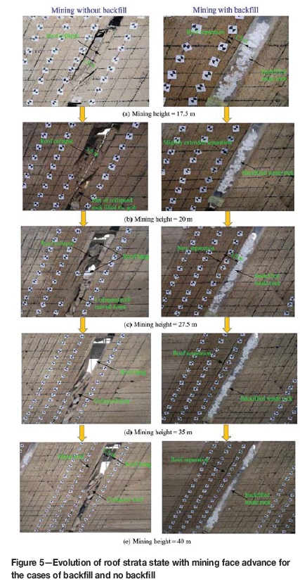
The second roof collapse during mining without backfill occurred when the vertical mining height reached 20 m, and the thickness of the collapsed roof strata increased to 3.5 m, approximately twice the thickness of coal seam, as shown in Figure 5b. The second collapse occurred mainly in the strata above the first collapse. There was no roof collapse close the mining face, owing due to support of the collapsed rock and the beam structure formed in the first collapse. When mining with backfill, as shown in Figure 5b, the roof separation propagated slightly, but no new separation appeared.
Figure 5c shows the state of the roof strata when the vertical mining height was 27.5 m. For mining without backfill, the third roof collapse occurred and the roof beam structure formed during the first collapse failed unstably due to the roof overhang. The collapsed rock mass moved down along the gob and filled the lower area. In the upper area, collapsed rock blocks formed a self-supporting structure and downward movement was temporarily restricted, resulting in a wide empty void in the middle of the gob area, as shown in Figure. 5c. For mining with backfill, a relatively large separation occurred 3.5 m above the mined seam, owing to the movement of backfilled waste rock down to the lower mined-out area when mining to 25 m, thus weakening the support of the roof strata.
When the vertical mining height reached 35 m, the fourth roof collapse occurred for mining without backfill, as shown in Figure 5d. On this occasion, the arch structure formed during the third roof collapse broke and the rock block subsided to fill the gob area. When mining with backfill, the roof strata remained stable and the existing separation did not extend further due to the continued action of the backfill.
Figure 5e shows the deformation and failure modes of surrounding rock strata at a mining height of 40 m. Without backfill, the initial caving step distance was 17.5 m and the periodic caving step distance was 7.5 m. The collapsed roof strata covered 3.5 m in the vertical direction, approximately twice the thickness of the mined coal seam. The downward movement of collapsed rock caused a relatively large empty zone to form at the top of mined-out stope and the roof strata collapse tended to be asymmetrical in the stope. When the gob was backfilled after each mining cut, separation occurred only in the roof strata.
Displacement of roof strata
For the case of backfilled mining, Figures 6 and 7 show, respectively, the cumulative vertical and horizontal displacements of roof strata at 2.5 m above the seam at different stages of mining. The maximum cumulative vertical and horizontal displacements were only 0.05 m when the vertical mining height was 17.5 m, due to support of the roof strata by the backfilled waste rock; only a slightly amount of bending deformation occurred. However, when the vertical mining height reached 25 m, there was a sudden increase in roof deformation, with maximum vertical and horizontal displacements of 0.2 m and 0.3 m, respectively. A relatively large separation appeared, due to the delay in providing backfill during the normal process of cut and fill. In subsequent mining from vertical heights of 25 m to 40 m, the cumulative vertical and horizontal displacements increased gradually and the previously developed roof separation extended only slightly, but new roof separation did not occur.
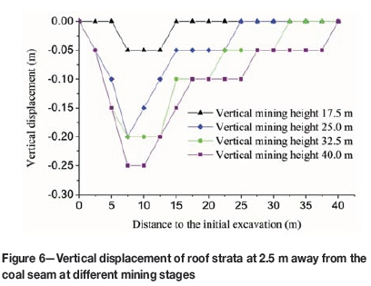
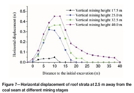
Another important phenomenon illustrated in Figures 6 and 7 is that, at any mining stage, both the largest cumulative vertical and horizontal displacements occurred 5 to 15 m from the first cut of mining. This is attributed to a complex interactive mechanism between the rock strata and backfill. Generally speaking, subsidence of the roof strata initially compacted the backfill and a certain amount of roof deformation occurred due to the loose nature of backfill at the early stage. With advance of the mining face and subsequent backfilling, the top backfill tended to move downwards, further weakening the backfill support. Unmined coal blocks opposite to the mining direction also provided support and transferred a portion of the roof strata load to the floor. This helped to reduce deformation of the roof strata within 5 m from the first cut of mining.
Pressure variation in roof strata
Figure 8 shows the pressure variation in the roof strata for mining a steep coal seam without backfill. At the start of mining, the pressure variation is very small because the hanging area of the roof strata is small and there is no obvious roof separation. The first cut of mining is marked as the reference point in Figure 3. When the face advanced vertically to 17.5 m, the first roof collapse occurred, reducing the stress in the roof strata 7.5 m below the first mining cut to zero. Before the first roof collapse, stress concentration in the roof strata occurred 2.5 m above and 20 m below the first cut; these stresses increased to 12.15 MPa and 11.67 MPa, corresponding to stress concentration coefficients of 1.35 and 1.30, respectively. However, following the first roof collapse, slight stress release occurred in roof strata 20 m below the initial excavation. With the second roof collapse, when the face advanced to 27.5 m, stress in roof strata 20 m below the initial excavation reduced to zero, while that 2.5 m above the initial excavation continued to increase to 14.82 MPa, corresponding to a stress concentration coefficient of 1.65. Such stress increases ceased when the mining face advanced to 27.5 m in the vertical direction, indicating that the roof strata at this position were no longer influenced by the mining face. Figure 8 also reveals that significant stress redistribution occurred with roof strata collapse within the disturbed zone.
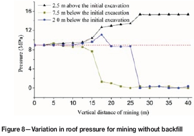
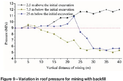
Figure 9 shows the pressure variation in the roof strata with backfill. Mining with backfill in general significantly reduces the impact on rock strata, including stress release and stress concentration. Stress release occurred when the mining face passed the monitoring points; however, the stress finally stabilized at a level of approximately 5 MPa, rather than zero. The degree of stress concentration also reduced with backfill. Considering roof strata located 2.5 m above the first cut of mining as an example, the final stress concentration coefficient was only 1.33, compared with 1.65 for mining without backfill. A comparison of Figure 8 with Figure 9 also shows that the vertical disturbance due to mining was shortened to approximately 22.5 m, 18% less than that in mining without backfill.
Effect ofbackfill extent on strata mechanics
Numerical modelling was used to investigate the effect of backfill extent on strata mechanics in steeply dipping seam coal mining.
Failure mode and crack development
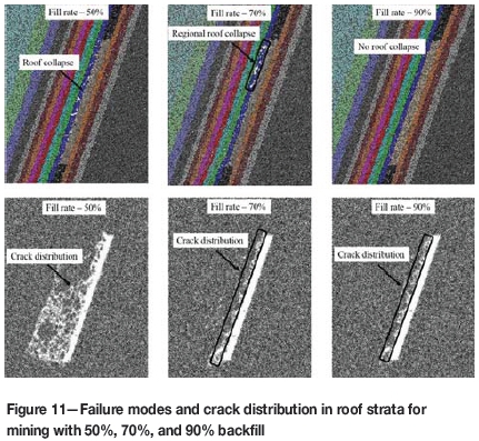
Figure 10 shows the roof collapse for mining without backfill. A wide range of roof strata were damaged and the 8 m thick siltstone (which has relatively low strength) above the gob area caved in. The collapsed material moved down and filled the lower part of gob area, providing support for the roof strata and hence restricting the propagation of roof cave-in. Figure 10 also demonstrates that collapse of roof strata was distributed asymmetrically.
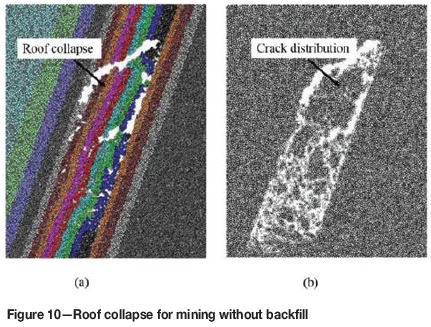
Figure 11 shows the failure modes and crack distribution in the roof strata for mining with 50%, 70%, and 90% backfill. In comparison with Figure 10, roof conditions were significantly improved by backfill mining. With 50% backfill only the roof strata 1 m above the gob collapsed; however, mining-induced cracks were still widely distributed across the entire siltstone layer. When the backfill increased to 70%, the space left for roof activity was reduced and support contributed by the backfill increased; as a consequence, roof conditions improved and only local collapse occurred in the strata located at the top part of gob area, as shown in Figure 11. With a further increase of backfill to 90%, roof collapse was almost eliminated; simultaneously, the range of mining-induced cracking was markedly reduced, occurring only in the immediate roof of the coal seam.
Displacement distribution and direction
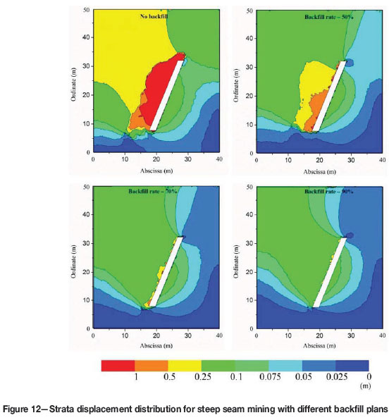
The displacement of rock strata after mining using different backfill plans is shown in Figure 12. The largest displacement was asymmetrically distributed and obliquely biased upwards for mining without backfill; with backfill, the magnitude and range of the largest displacement were significantly reduced. Such displacement reduction continued with increasing extent of backfill.
The direction of the displacement angle of rock strata particles was investigated statistically using the built-in programming language FISH and is shown in Figure 13. The displacement direction angles of rock particles fell into two ranges: 160°-180° and 260°-320°. Particles of floor strata fell mainly in the former range, while roof strata fell mainly in the latter range, indicating that floor and roof strata mainly undergo nearly horizontal and nearly vertical displacements towards the mined-out void, respectively.
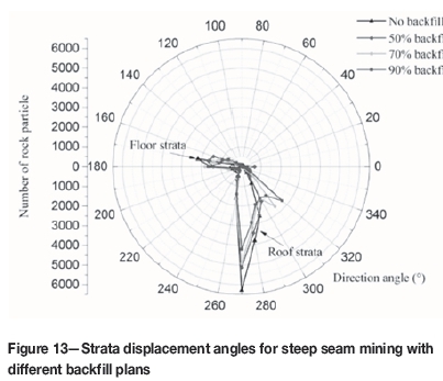
Figure 13 also shows that the backfill and extent of fill influence the displacement angle of the rock strata, particularly the roof strata. Without backfill, the displacement direction angle of roof strata varied between 260° and 290°; as the extent of backfill increased, the range of displacement direction angles became larger: 260-300° at 50%, 260-310° at 70%, and 260-320° at 90% backfill. The range of displacement direction angle also increased with increasing backfill, tending to become evenly distributed and indicating good integrity of the roof strata. The variation of displacement angle in the floor strata was smaller. This indicates that, with an increase in backfill, the integrity of roof strata was maintained and they deformed as a whole with an evenly distributed direction angle of displacement.
Implications for steep-seam coal mining
For mining without backfill, three types of strata movement can be categorized. The first is bending deformation towards the gob area, which occurs during the early stage of mining, starting from the immediate roof and extending along the vertical direction of roof strata. This type of deformation is continuous until roof separation occurs.
The second type of movement is collapse of the roof strata. As mining advances, the cumulative bending deformation of roof strata becomes large and the developed stress exceeds the threshold of the strata. Cracks then initiate, propagate, and coalesce in the immediate roof strata, finally leading to roof collapse. The collapsed rock blocks move down along the dip direction of the seam and fill the lower part of the gob area. With cave-in of the immediate roof, major roof strata gradually subside, and a new round of roof separation starts. During this process, stress in released in roof strata above the top part of gob, while stress continues to concentrate in unmined coal blocks, creating a high abutment pressure. At the lower part of gob area, the collapsed rock blocks move downwards and support the roof strata to some extent, reducing subsidence. Roof collapse in steeply dipping coal seam mining without backfill therefore tends to be asymmetric; the movement and damage experienced by roof strata at the upper part of gob area are far larger than those at the low part.
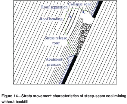
The third type of movement is slip along the weak plane. For steeply dipping coal seam mining, the gravitational direction is not normal to the roof strata; hence, roof strata not only undergo bending deformation towards the gob, but also tend to slip down along the bedding plane. This is distinctly different from strata movement in flat coal seams. The upper roof strata are therefore in a tensile state, while the lower roof strata are in a compressive state. This is schematically shown in Figure 14.
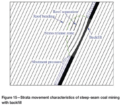
Waste rock used to backfill the mined-out void after each cut tends to move downwards under the influence of gravity. Because the initial backfill is relatively loose and compressible during the early stage, roof strata incur a certain amount of subsidence. Once the subsided roof strata contact the backfill, the subsidence rate gradually decreases. The load-bearing capacity of the backfill increases during this process. The gradually compacted backfill resists subsidence of the roof strata and transfers the burden to the floor strata. As a result, the size of the stress release zone in the overlying rock strata and the stress concentration in the unmined coal seam block are reduced. The characteristics of strata movement in steep coal seam mining with backfill are schematically presented in Figure 15.
The extent of backfill has a significant impact on strata movement in steep-seam coal mining. Roof conditions can be improved by increasing the amount of backfill and roof collapse can be completely eliminated when the extent of fill reaches a threshold value. With backfill, the variation in displacement direction angle of the floor strata is less than that of the roof strata, indicating that deformation control by backfilled rock is more effective in roof strata than in floor strata. As the extent of backfill increases, the integrity of the roof strata is maintained and they deform as a whole, with an evenly distributed direction of displacement.
Field trial
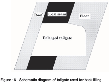
A field trial was conducted in no. 5 coal seam of Datai mine, China. The tailgate was enlarged, as shown in Figure 16, to meet the requirements of normal production and backfill equipment layout.
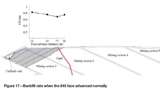
Mining sections 2 and 3 were co-extracted, as shown in Figure 17. Backfilling was carried out simultaneously with extraction. When the mining face advanced to 96 m, the mining void was 3115 m2. Figure 17 shows that the backfilling was well conducted (except for the existence of an unfilled triangular void in the vicinity of the first cut of mining section 2); the fill ratio was 67.7-82.4%. Timely backfill helped to maintain the rock surrounding the backfill tailgate in very good condition.
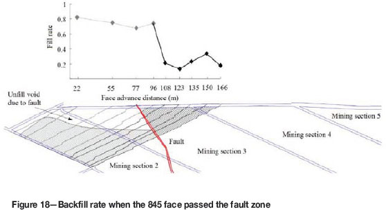
As the mining face advanced, a fault was encountered, as shown in Figures 17 and 18. Dislocation and slip occurred in the surrounding rock strata when the face passed the fault, and severe deformation led to cessation of the backfill operation. As the face advanced from 99 m to 166 m, as shown in Figure 18, the extent of fill dropped significantly, with minimum and maximum backfill extents of 13.3% and 34.2%, respectively.
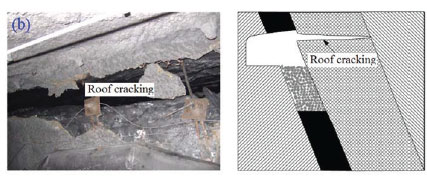
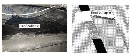
Deformation of roof strata of the backfill tailgate as the mining face advanced from the first cut of mining to 166 m is shown in Figure 19. During the early stage, starting from the first cut of mining, mining was conducted normally and the void was backfilled timeously with a high backfill extent. Roof deformation was effectively controlled and only slight roof bending occurred, as shown in Figure 19a. However, when the mining face passed the fault, the void in front of the fault could not be effectively backfilled due the dislocation and slip of the fault zone and so cracking occurred in the roof strata, as shown in Figure 19b. The opening height of the crack was approximately 0.5 m, and it extended the entire thickness of the immediate roof. As the mining face advanced, overhang of the roof strata increased, leading to roof collapse, as shown in Figure 19c. The lower part of the roof strata underwent downwards slip after the roof collapse due to the steep dip angle of the coal seam and deadweight of rock strata, as shown in Figure 19d. This is a specific characteristic of steeply dipping coal seam mining, which is distinctly different from flat coal seam mining. Breaking of roof strata started from the fault and extended to 170 m along the axial direction of the backfill tailgate, confirming the significance of using a high amount of backfill in ground control in steeply dipping coal seam mining. It should be noted that the fault also weakened the regional rock strata prior to backfilled mining. Such weak rock condition near the fault, combined with insufficient backfill extent, led to strata failure when the mining face advanced over the fault zone.


Conclusions
The deformation of rock strata in steep coal seam mining and its ground control with backfill were investigated by physical and numerical modelling, using the no. 5 coal seam of Datai coal mine, China, as the engineering prototype.
Without backfill, the initial roof collapse step distance was 17.5 m along the vertical direction and the step distance of periodic collapses was 7.5 m, was approximately twice the coal seam thickness. The collapsed rock mass moved down and filled the lower gob area, reducing roof subsidence in this area. There was a relative large empty zone in the upper part of stope due to the downward movement of collapsed rock, and the movement of roof strata tended to be asymmetrical.
With backfilling after each mining cut, the waste rock supported the roof strata and inhibited roof collapse. Initially backfilled waste rock was loose and of low stiffness, so bending deflection towards the gob area occurred, finally leading to a slight separation of the roof strata at 1.5 m above the mined seam. The largest cumulative vertical and horizontal displacements occurred 5-15 m away from the initial excavation, which is attributabed to a complex interactive mechanism between the rock strata and backfill. Physical modelling with full backfill extent revealed that the backfill improved the roof strata conditions. The stress finally stabilized at a level of approximately 5 MPa in the release zone and the stress concentration coefficient reduced to 1.33 in the concentration zone. The vertical range of mining-induced disturbance was reduced by 18% compared with that without backfill. With an increase in the extent of backfill, roof conditions improved significantly. Roof collapse can be prevented at a threshold backfill rate value. The integrity of the roof strata was improved with increasing extent of backfill and the concentration range of displacement direction angle was reduced.
Acknowledgments
The study is financially supported by National Natural Science Foundation of China (No. 51304256, No. 51604165 and No. 51404168) and Fundamental Research Funds for the Central Universities (No.106112015CDJXY240005). Special thanks go to Dr. Jan Nemcik, University of Wollongong, for suggestions during the manuscript preparation.
References
Bian, Z., Miao, X., Lei, S., Chen, S.E., Wang, W., and Struthers, S. 2012. The challenges of reusing mining and mineral processing wastes. Science, vol. 337. pp. 702-703. [ Links ]
Brady, B.H.G. and Brown, E.T. 2004. Rock Mechanics for Underground Mining. Kluwer, Dordrecht. [ Links ]
Cao, S. and Gou, P. 2011. Coal Mining (Underground Mining section). China Coal Industry Publishing House, Beijing. (In Chinese). [ Links ]
Doherty, J.P., Hasan, A., Suazo, G.H., and Fourie, A. 2015. Investigation of some controllable factors that impact the stress state in cemented paste backfill. Canadian Geotechnical Journal, vol. 52. pp. 1901-1912. [ Links ]
Fahey, M., Helinski, M., and Fourie, A. 2009. Some aspects of the mechanics of arching in backfilled stopes. Canadian Geotechnical Journal, vol. 46. pp. 1322--336. [ Links ]
Fahey, M., Helinski, M., and Fourie, A. 2011. Development of specimen curing procedures that account for the influence of effective stress during curing on the strength of cemented mine backfill. Geotechnical and Geological Engineering, vol. 29. pp. 709-723. [ Links ]
Fall, M., Celestin, J.C., Pokharel, M., and Touré, M. 2010. A contribution to understanding the effects of curing temperature on the mechanical properties of mine cemented tailings backfill. Engineering Geology, vol. 114. pp. 397-413. [ Links ]
Fall, M. and Nasir, O. 2010. Mechanical behavior of the interface between cemented tailings backfill and retaining structures under shear loads. Geotechnical and Geological Engineering, vol. 28. pp. 779-790. [ Links ]
Galaa, A.M., Thompson, B.D., Grabinsky, M.W., and Bawden, W.F. 2011. Characterizing stiffness development in hydrating mine backfill using ultrasonic wave measurements. Canadian Geotechnical Journal, vol. 48. pp. 1174-1187. [ Links ]
Helinski, M., Fahey, M., and Fourie, A. 2011. Behavior of cemented paste backfill in two mine stopes: measurements and modeling. Journal of Geotechnical and Geoenvironmental Engineering, vol. 137. pp. 171-182. [ Links ]
Hughes, P.B., Pakalnis, R., Hitch, M., and Corey, G. 2010. Composite paste barricade performance at Goldcorp Inc. Red Lake Mine, Ontario, Canada. International Journal of Mining, Reclamation and Environment, vol. 24. pp. 138-150. [ Links ]
Itasca. 2008. PFC2D-Particle flow code in 2 dimensions, version 4.0 user's manual, itasca Consulting Group inc., Minneapolis. [ Links ]
Jeremic, M. 1985. Strata Mechanics in Coal Mining, CRC Press. [ Links ]
Ju, F., Huang, P., Guo, S., Xiao, M. and Lan, L. 2017. A roof model and its application in solid backfilling mining. International Journal of Mining Science and Technology, vol. 27. pp. 139-143. doi: https://doi.org/10.1016/j.ijmst.2016.11.001 [ Links ]
Klein, K. and Simon, D. 2006. Effect of specimen composition on the strength development in cemented paste backfill. Canadian Geotechnical Journal, vol. 43. pp. 310-324. [ Links ]
Kostecki, T. and Spearing, A.J.S. 2015. Influence of backfill on coal pillar strength and floor bearing capacity in weak floor conditions in the illinois Basin. International Journal of Rock Mechanics and Mining Sciences, vol. 76. pp. 55-67. [ Links ]
Kulakov, V.N. 1995. Geomechanical conditions of mining steep coal beds. Journal of Mining Science, vol. 31. pp. 136-143. [ Links ]
Kulakov, V.N. 1995. Stress state in the face region of a steep coal bed. Journal of Mining Science, vol. 31. pp. 161-168. [ Links ]
Li, L. and Aubertin, M. 2009a. Horizontal pressure on barricades for backfilled stopes. Part I: Fully drained conditions. Canadian Geotechnical Journal, vol. 46. pp. 37-46. [ Links ]
Li, L. and Aubertin, M. 2009b. Numerical investigation of the stress state in inclined backfilled stopes. International Journal of Geomechanics, vol. 9. pp. 52-62. [ Links ]
Li, L. and Aubertin, M. 2011. Limit equilibrium analysis for the design of backfilled stope barricades made of waste rock. Canadian Geotechnical Journal, vol. 48. pp. 1713-1728. [ Links ]
Mishra, M. and Karanam, U.M.R. 2006. Geotechnical characterization of fly ash composites for backfilling mine voids. Geotechnical and Geological Engineering, vol. 24. pp. 1749-1765. [ Links ]
Mkadmi, N.E., Aubertin, M., and LI, L. 2013. Effect of drainage and sequential filling on the behavior of backfill in mine stopes. Canadian Geotechnical Journal, vol. 51. pp. 1-15. [ Links ]
Mo, S., Canbulat, I., Zhang, C., Oh, J., Shen, B., and Hagan, P. 2017. Numerical investigation into the effect of backfilling on coal pillar strength in highwall mining. International Journal of Mining Science and Technology. https://doi.org/10.1016/j.ijmst.2017.07.003 [ Links ]
O'Sullivan C. 2011. Particulate Discrete Element Modelling: A Geomechanics Perspective. Spon Press. [ Links ]
Potyondy, D.O. and Cundall, P.A. 2004. A bonded-particle model for rock. International Journal of Rock Mechanics and Mining Sciences, vol. 41. pp. 1329-1364. [ Links ]
Sivakugan, N., Rankine, R.M., Rankine, K.J., and Rankine, K.S. 2006. Geotechnical considerations in mine backfilling in Australia. Journal of Cleaner Production, vol. 14. pp. 1168-1175. [ Links ]
Sui, W., Zhang, D., Cui, Z.C., Wu, Z., and Zhao, Q. 2015. Environmental implications of mitigating overburden failure and subsidences using paste-like backfill mining: a case study. International Journal of Mining, Reclamation and Environment, vol. 29. pp. 521-543. [ Links ]
Tesarik, D.R., Seymour, J. B., and Yanske, T.R. 2009. Long-term stability of a backfilled room-and-pillar test section at the Buick Mine, Missouri, USA. International Journal of Rock Mechanics and Mining Sciences, vol. 46. pp. 1182-1196. [ Links ]
Thompson, B.D., Bawden, W.F. and Grabinsky, M.W. 2012. In situ measurements of cemented paste backfill at the Cayeli Mine. Canadian Geotechnical Journal, vol. 49. pp. 755-772. [ Links ]
Walske, M.L., McWilliam, H., Doherty, J., and Fourie, A. 2016. Influence of curing temperature and stress conditions on mechanical properties of cementing paste backfill. Canadian Geotechnical Journal, vol. 53, no. 1. pp. 148-161. [ Links ]
Wang, H., Poulsen, B.A., Shen, B., Xue, S., and Jiang, Y. 2011. The influence of roadway backfill on the coal pillar strength by numericalinvestigation. International Journal of Rock Mechanics and Mining Sciences, vol. 48. pp. 443-450. [ Links ]
Yilmaz, E., Belem, T., and Benzaazoua, M. 2014. Effects of curing and stress conditions on hydromechanical, geotechnical and geochemical properties of cemented paste backfill. Engineering Geology, vol. 168. pp. 23-37. [ Links ]
Paper received Dec. 2016
Revised paper received May 2017

