


Servicios Personalizados
Articulo
 Inglés (pdf)
 Articulo en XML
 Referencias del artículo
Indicadores

Links relacionados
-
 Citado por Google
 -
 Similares en Google
Compartir

 Permalink
Journal of the Southern African Institute of Mining and Metallurgy
versión On-line ISSN 2411-9717
versión impresa ISSN 2225-6253
J. S. Afr. Inst. Min. Metall. vol.117 no.12 Johannesburg dic. 2017
http://dx.doi.org/10.17159/2411-9717/2017/v117n12a8
PAPERS OF GENERAL INTEREST
An improved method of testing tendon straps and weld mesh
B.P. WatsonI; D. van NiekerkII; M. PageII
IVisiting Professor - School of Mining Engineering,University of the Witwatersrand, South Africa
IIPrivate Consultant
SYNOPSIS
There is currently no standard method of evaluating tendon straps and weld mesh for underground excavation support in South Africa. At the request of suppliers, the CSIR has been conducting pure tensile tests on these elements with all the strands clamped in a jig. Even though the actual in situ loading is usually quite different, the manufacturers have required pure tensile results. In an underground situation, these support units are loaded by a block or set of blocks perpendicular to the strands under the influence of gravity. This loading results in a combination of tensile stresses and bending moments at the point of fixture, which is not adequately represented by a pure tensile test. In this paper we describe a more representative test which caters for a worst-case loading condition due to block rotation. An improved design of tendon strap to better cope with the loading environment is also described.
Keywords: eccentric loading, load-bearing capacity, bending moments, strength requirement, realistic laboratory test.
Introduction
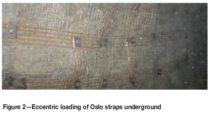
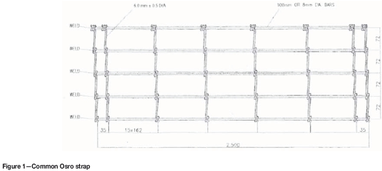
The mechanized deep-level mines in South Africa have been using tendon straps (locally referred to as Osro straps) together with weld mesh for the support of longer term excavations. Traditionally, the Osro straps are 300 mm wide and consist of five 10 mm diameter strands along the length (Figure 1). The connecting strands are generally 6 mm in diameter and spaced 150 mm apart along the width, as shown in the figure. The five-strand geometry encourages eccentric loading underground, with clamping of different strands along the length of the strap (Figure 2).
The Osro strap is normally installed with long anchors and dome washers over the existing primary support. The primary support commonly consists of 5.6 mm diameter weld mesh with 100 mm apertures, installed with tendons. One deep-level gold mine reported a dramatic drop in injuries since the introduction of the mesh and straps (Pretorius, 2010).
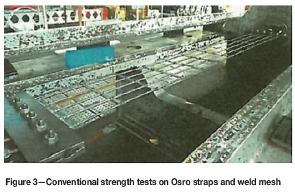
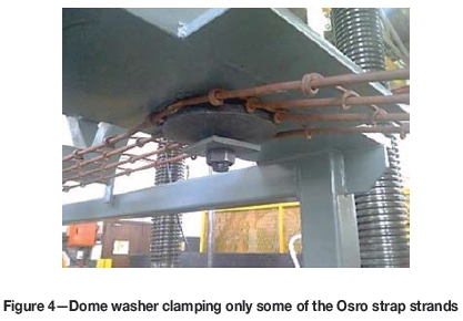
In the absence of a documented standard on how to test mesh and Osro straps, the manufacturers of these products requested the CSIR to perform a tensile pull-test to determine strength and quality (Bergh, 2016). The strands are clamped on either end as shown in Figure 3 and the element is loaded in tension until failure. However, a significant over-estimation of the load-bearing capacity is provided by this test due to the disparate loading condition underground. In underground applications, clamping is provided by tendons located on the corners of the mesh (usually 150 mm in from the corners for mesh overlap) and the ends of the Osro straps, and loading takes place perpendicularly to the strands. A typical dome washer is 200 mm in diameter and can load a maximum of only two or three strands due to its size (Figure 4) and the uneven rock surface. Generally, two of the strands are doing little work during loading underground. This paper investigates whether the quoted tensile strengths are sufficient, or could the support elements be over- or under-designed? A suitable testing apparatus was therefore constructed to cater for a worst-case, underground loading environment, and tests were conducted at the CSIR in Johannesburg. The load demand requirements were calculated assuming the maximum likely dead-weight load of loose rock between support tendons.
Literature review
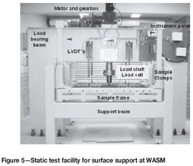
Mesh research was undertaken in South Africa by Rand Mines limited (Ortlepp, 1983) and in Canada by the Ontario Ministry of Labour (Pakalnis and Ames, 1983) in the early 1980s. Large-scale mesh tests were conducted by Tannant, Kaiser, and Maloney (1997) and Thompson, Windsor, and Cadby (1999) to determine the force-displacement reaction properties of mesh when loaded perpendicular to the strands. In 2005, a large-scale static testing facility was designed and built by the Western Australian School of Mines, based on insights provided by the previous research. Two test programms were undertaken by Player et al. (2008) to assess the static and dynamic properties of welded wire and chain link meshes.
The WASM static test facility is shown in Figure 5. It comprises two steel frames, which provide a loading condition perpendicular to the mesh or surface support. The mesh sample is restrained within a stiff frame that rests on the support frame. The restraint system consists of high-strength eye nuts, D-shackles, and threaded bar passing through a perimeter frame at allocated points as shown in Figure 6.
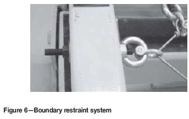
This system, although providing repeatable results, does not fully represent the loading dynamics underground. In particular, Osro straps are generally clamped by dome washers and bolts that are pre-tensioned to 18 t. Loading would subsequently cause bending moments at the washer and edge of the loading block. Numerical analysis was performed to determine the effects of such a loading configuration on a strap.
Numerical stress analysis
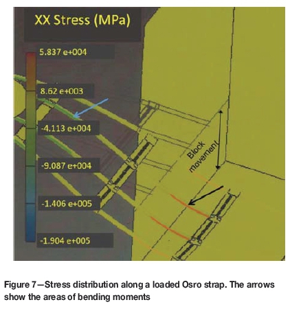
Finite element modelling (Solidworks, 2014) was carried out to determine the stress distribution along an Osro strap during loading. The results clearly show the tensile and compressive stresses resulting from the bending moments at the edge of the loading block and dome washer (Figure 7). These stress concentrations do not develop in a standard pull-test and therefore the standard test over-estimates the strength of the strap. Thus the modelling shows the importance of using the same loading configuration as underground to establish true strap and mesh strengths. Shackles do not provide a true boundary constraint as the bending moments are less pronounced. A test rig was therefore designed to load against a dome washer.
Typical underground support configuration
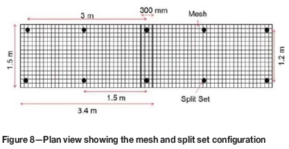
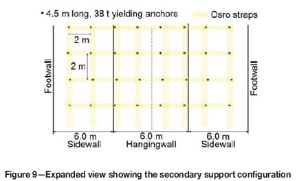
The current primary support in the access and infrastructure excavations of South African mechanized gold mines generally consists of 2.4 m long split sets, spaced about 1.2 m χ 1.5 m, and weld mesh (Figure 8). Both the mesh and split sets are installed remotely using twin-boom drill rigs or bolters. In the more permanent ramps and haulages, secondary support is installed in the form of 4.5 m long, 38 t anchors, spaced about 2 m χ 2 m apart, with Osro straps across and along the direction of the tunnels (Figure 9).
Underground loading environment
Assuming that the secondary support anchors are installed deep enough to anchor into competent ground, the mesh and Oslo straps need to contain the loose rock between the tendons. The size and mass of the unstable rock requiring containment can be approximated by a square pyramid, with a height of half the spacing between the tendons (Figure 10).
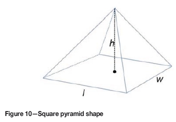
The strength requirements of the mesh and Osro strap support elements are therefore calculated assuming the weight of loose rock within this shape:

where:
L = Weight
δ = Density
g = Gravitational acceleration (9.81 m/s2)
l,w, and h are the dimensions of the pyramid assuming h= 1/2l (Figure 10).
Laboratory testing
A test rig has been designed to cater for the worst-case loading scenario. It includes the bending moments shown in the model results and the guillotine effects of the dome washer on the outer strap. (There will almost always be a connecting or crossing strap that will not be exposed to the guillotine effects of the washer.) In addition, the sharp edges of loading blocks, typical of the Witwatersrand quartzites in the gold mines, are also considered.
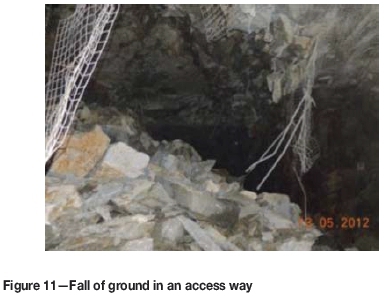
Typical blocks observed in falls of ground on the intermediate- to deep-level gold mines are relatively small (approx. 1 m χ 0.5 m χ 0.3 m). The commonly observed sharp edges are shown in Figure 11. Worst-case loading conditions would be caused by the acute bending that occurs along the edges of these blocks.
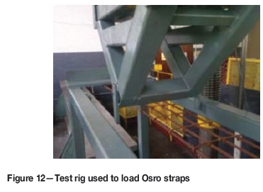
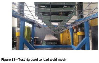
The rig design consisted of a rectangular frame of the same length as a standard length of weld mesh (3.4 m) or tendon spacing along an Osro strap. The element is attached to the base of the rig by short bolts and washers to replicate the conditions underground (Figure 4). The assembly is loaded from the top by a line-shaped plunger (Figure 12 and Figure 13). The loading shape represents a block of rock that has rotated and is loading the support element along its edge. The length of the loading line was 0.5 m to coincide with a typical block size.
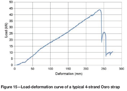
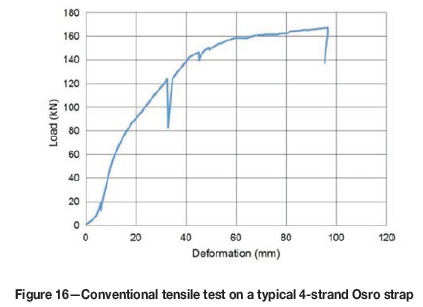
Peak failure Loads of 18 kN and 44 kN were typical for the mesh and straps strands, respectively. A common tensile test on the same Osro strap will provide loads of about 170 kN.
Test method comparison
A typical load-deformation curve for weld mesh under the described line-loading condition with a 0.5 m long plunger is shown in Figure 14. Note that the first strand failed at about 18 kN.
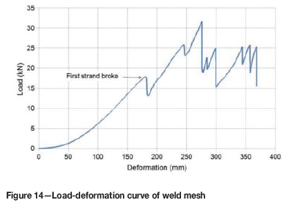
Using the pyramid model, the strength requirement of such mesh where the support elements are spaced 2 m χ 2 m is 35 kN (ignoring the support effects of the split sets). Obviously, the mesh on its own is insufficient, requiring straps as additional reinforcement. A similar test performed on a normal four-strand Osro strap with 10 mm strands will provide 44 kN (Figure 15). The significant safety factor allows for some corrosion. Note that only two strands were clamped during the test, as shown in Figure 4.
Conventional tensile testing of the strap provides strength results that are 'not applicable' for estimating load resistance in an underground mine situation, as shown in Figure 16. Apart from ignoring the bending moments, it is impossible for all the strands to be equally loaded and to contribute to the overall element strength in the underground environment.
Financial implications
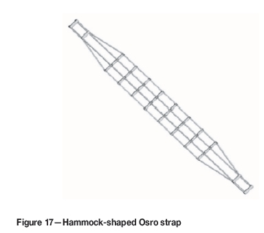
A normal 300 mm wide Osro strap will cost about R280, but a two-strand strap will do almost the same work for R100. However, the areal coverage is small, with a possibility of falls of ground (FOGs) between the straps. Nonetheless, a wider strap can be designed with a hammock shape to cater for the area of the clamping washer. In this instance the washers would be located in the narrow ends.
Hammock-shaped Osro strap
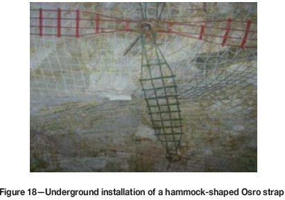
The hammock shape (Figure 17) allows a 200 mm washer, located in the narrow end, to load over all four strands and maintain the standard 300 mm strap-width. An underground installation of the strap is shown in Figure 18.
Laboratory tests on the hammock design
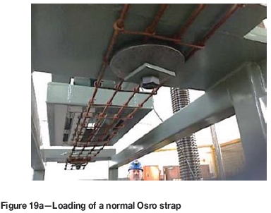
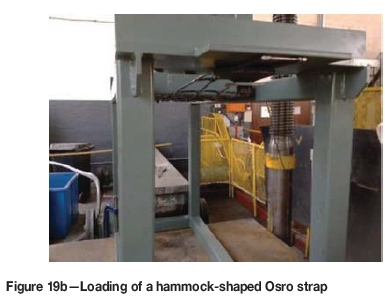
Strength tests were performed on the normal and hammock-shaped straps using the suggested testing apparatus (Figure 19a and Figure 19b). The results of the investigation are shown in Figure 20. As expected the hammock shape is stronger and stiffer than the normal shape.
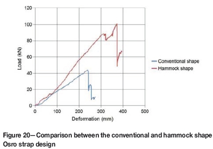
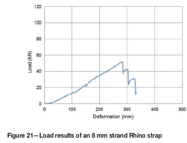
The hammock-shaped strap in Figure 20 is significantly over-designed for a 2 m χ 2 m tendon spacing and a narrower gauge strand can therefore be considered, which would reduce costs and be easier to install around corners.
An 8 mm diameter strand strap was tested and the strength was shown to be adequate for the described tendon spacing (Figure 21).
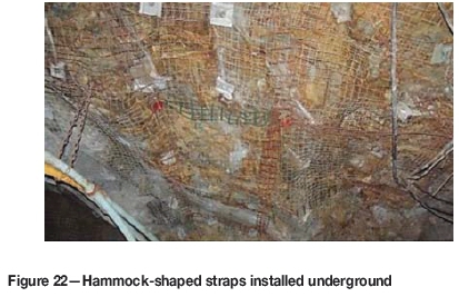
Underground investigations
An underground trial was initiated on a deep-level gold mine to determine any installation difficulties (Figure 22). The limited tolerance on the position of a tendon in the standard hammock design meant that tendons could not be moved to avoid bridging across ridges in an uneven hanging- or sidewall. However, this problem can be resolved by increasing the length of the hammock neck for straps used in uneven and blocky ground conditions.
Discussion
A more realistic laboratory test shows that the standard South African tensile testing of Osro straps and weld mesh provides strength values that are not applicable for establishing load-bearing capacity in underground mine situations. However, the mesh and Osro straps only need to contain the loose rock between properly installed tendons. The required strength is therefore relatively small and easily achieved if two strands are clamped. The standard 10 mm thick Osro strap could be considered as over-designed because only two of the five strands are carrying the load. It should also be remembered that there is a risk, in an underground environment, for only one strand to be properly clamped due to the uneven surface and eccentric loading. An Osro strap designed in the form of a hammock, however, improves clamping and ensures that all the strands are loaded. Using this design, it is possible to reduce the strand thickness to 8 mm and still maintain sufficient load-bearing capacity. The mass of such a strap is considerably less and it is also easier to bend around corners.
It should be noted that the analysis presented here deals only with static loading conditions, and does not consider dynamic loading in rockbursting situations.
Conclusions
It has been shown that in tests simulating underground loading conditions, Osro straps and weld mesh fail at significantly lower loads than predicted by the standard tensile tests. A test frame that creates a more realistic loading condition has been developed to simulate actual loading conditions. The research showed that the standard 5.6 mm diameter weld mesh is insufficient on its own if the secondary support tendons are installed at the common 2 m χ 2 m spacing. Osro straps are thus required to strengthen the areal coverage support. Normal Osro straps with 10 mm diameter strands are sufficient to carry the unstable load. However, there are strands that are not clamped due to the size of the dome washer, uneven surface underground, and eccentric loading. Such strands are carrying little load and most of the work is done by one or two strands at the centre of the strap. A hammock-shaped strap with four strands has been designed to better accommodate the underground constraints. Tests have proved that such a design significantly increases the strength and stiffness of the strap. The current 10 mm diameter longitudinal strands are an over-design if this shape is employed. Under such conditions, 8 mm diameter strands are sufficient to provide the required load-bearing capacity on a 2 m anchor spacing. This will bring down the mass and make the strap more user-friendly.
The paper deals only with static loading conditions, and may not be applicable to dynamic loading in rockbursting situations.
References
Bergh, R. 2016. Personal communication. CSIR, Johannesburg, South Africa. [ Links ]
Ortlepp, W.D. 1983. Considerations in the design of support for deep hard rock tunnels. Proceedings of the 5th International Congress on Rock Mechanics, vol. 2. Balkema, Rotterdam. pp. 179-187. [ Links ]
Pakalnis, V and Ames, D. 1983. Load tests on mine screening. Underground Support Systems. Udd, J. (ed.). Special Volume 35. Canadian Institute of Mining Metallurgy and Petroleum, Montreal. pp. 79-83. [ Links ]
Player, J.R., Morton, E.C., Thompson, A.G., and Villaescusa, E. 2008. Static and dynamic testing of steel wire mesh for mining applications of rock surface support. Proceedings of the 6th International Symposium on Ground Support in Mining and Civil Engineering Construction, Cape Town, 30 March - 3 April 2008. Southern African Institute of Mining and Metallurgy, Johannesburg. pp. 693-706. [ Links ]
Pretorius, W. 2011. Personal communication. Randfontein, South Africa. [ Links ]
Solidworks. 2014. www.solidworkstutorials.com [ Links ]
Tannant, D, Kaiser, P.K., and Maloney S. 1997. Load - displacement properties of welded - wire, chain - link and expanded metal mesh. Proceedings of the International symposium on Rock Support - Applied Solutions/or Underground Structures, Lillehammer, Norway, 22-25 June 1997. Broch, E., Myrvang, A., and Stjern, G. (eds.). Norwegian Society of Chartered Engineers. pp. 651-659. [ Links ]
Thompson, A.G., Windsor, C.R., and Cadby, G.W. 1999. Performance assessment of mesh for ground control applications. Rock Support and Reinforcement Practice in Mining. Villaescusa, E., Windsor, C.R., and Thompson, A.G. (eds.). Balkema, Rotterdam. pp. 119-130. [ Links ]
Paper received Sep. 2016
Revised paper received Sep. 2017

