


Serviços Personalizados
Artigo
 Inglês (pdf)
 Artigo em XML
 Referências do artigo
Indicadores

Links relacionados
-
 Citado por Google
 -
 Similares em Google
Compartilhar

 Permalink
Journal of the Southern African Institute of Mining and Metallurgy
versão On-line ISSN 2411-9717
versão impressa ISSN 2225-6253
J. S. Afr. Inst. Min. Metall. vol.117 no.11 Johannesburg Nov. 2017
http://dx.doi.org/10.17159/2411-9717/2017/v117n11a9
PAPERS OF GENERAL INTEREST
SEM image processing as an alternative method to determine chromite pre-reduction
G.T.M. Mohale; J.P. Beukes; E.L.J. Kleynhans; P.G. van Zyl; J.R. Bunt; L.R. Tiedt; A.D. Venter; A. Jordaan
Chemical Resource Beneficiation North-West University, Potchefstroom Campus, South Africa
SYNOPSIS
The specific energy consumption (SEC) of the pelletized chromite prereduction process is the lowest of all FeCr production processes commercially applied. This process also eliminates the use of chromite ore fines that could result in furnace blow-outs or so-called bed turnovers, yields a high chromium (Cr) recovery, and can produce a low-sulphur (S) and -silicon (Si) FeCr. However, this process requires extensive operational control due to the variation in pre-reduction levels and carbon contents of the pre-reduced, pelletized furnace feed material. The wet chemical analytical method currently applied for the determination of chromite pre-reduction is time-consuming. In this paper, the development of an alternative method consisting of scanning electron microscopy (SEM) micrograph image processing is presented. A strong linear correlation (R2 = 0.919) between chromite pre-reduction (%), as determined by wet chemical analysis, and the new method was obtained. Further development could result in the industrial application of the method, which could contribute significantly to the metallurgical stability and enhanced process control of the pelletized chromite pre-reduction process.
Keywords: chromite pre-reduction, solid-state reduction of chromite, scanning electron microscopy (SEM), image processing, metallurgical carbon balance.
Introduction
Chromite ore has remained the only commercially viable source of new chromium (Cr) units since its discovery (Riekkola-Vanhanen, 1999). South Africa holds the majority of the world's exploitable chromite reserves (Cramer, Basson, and Nelson, 2004). More than 90% of all chromite is smelted using pyrometallurgical carbothermic reduction to form various grades of ferrochrome (FeCr) -a crude alloy principally containing Cr and iron (Fe) (ICDA, 2013). Over 80% of FeCr is used for the production of different stainless steel grades (ICDA, 2013; Murthy, Tripathy, and Kumar, 2011; Abubakre, Muriana, and Nwokike, 2007). Stainless steel products play an important role in modern-day society due to their resistance to corrosion (Riekkola-Vanhanen, 1999).
The FeCr industry utilizes various preprocessing and smelting methods, with the following being the most well-defined (Beukes, Dawson, and van Zyl, 2010; Naiker, 2007; Daavittila, Honkaniemi, and Jokinen, 2004; Riekkola-Vanhanen, 1999).
> Conventional semi-closed or open submerged arc furnace (SAF) operations that mainly utilize coarse chromite, flux, and carbonaceous reductant feed materials. This process requires the lowest capital input, since minimal preprocessing of the feed materials is necessary. However, it is the least environmentally friendly and the least efficient in terms of Cr recovery and specific energy consumption (SEC), i.e. MWh/ton FeCr produced
> Closed SAF operations that mainly utilize oxidative sintered chromite pellets, as well as coarse flux and reductant as feed materials (e.g. Outotec process). A significant proportion of green- and brownfield FeCr developments over the last two decades utilize this technology
> Closed SAF operation combined with pelletized pre-reduced chromite, as well as coarse fluxes and reductants as feed material (e.g. the Premus process applied by Glencore-Xstrata Alloys)
> Closed SAF with plasma or direct current (DC) arc operation that can be fed fine material exclusively, which eliminates pre-processing of raw materials. However, this process option has the highest SEC.
In this paper, the focus is on the pelletized chromite pre-reduction process (also referred to as solid-state reduction of chromite), which is applied at two FeCr smelters in South Africa that currently account for a combined production capacity of about 1.13 Mt of FeCr annually (Jones, 2014; Beukes, van Zyl, and Ras, 2012). FeCr smelters applying this process are also being developed in China, but information regarding production capacities of these facilities is not yet available in the public domain. In the pelletized chromite pre-reduction process, fine chromite ore, a clay binder, and a carbon reductant are dry-milled, agglomerated (pelletized), and pre-reduced (solid-state reduction) in a rotary kiln at temperatures up to 1 400°C (Niayesh and Fletcher, 1986). The pre-reduced pellets are then charged hot, immediately after exiting the kiln, into a closed SAF (Beukes, Dawson, and van Zyl, 2010; Naiker, 2007). If chromite pellets made from typical South African chromite ore are pre-reduced to approximately 45%, the SEC of the pelletized chromite prereduction process is approximately 2.4 MWh/t FeCr, which is the lowest of all FeCr production processes commercially applied (Kleynhans etal., 2017a; Beukes, Dawson, and van Zyl, 2010; Takano et al., 2007; Naiker, 2007; Niayesh and Fletcher, 1986). The SEC is of particular importance, since electricity consumption is the single largest contributor to the overall FeCr production costs (Kleynhans et al., 2017b; Biermann, Cromarty, and Dawson, 2012; Daavittila, Honkaniemi, and Jokinen, 2004). Other advantages associated with the application of the pelletized chromite pre-reduction process are that it: (i) eliminates the use of chromite fines that could sinter on the surface of the furnace bed materials, which could trap evolving gases and can result in blow-outs or so-called bed turnovers, (ii) yields a high Cr recovery of approximately 90%, (iii) can produce low-sulphur (S) FeCr due to the use of a highly basic slag, and (iv) can produce a relatively low-silicon (Si) FeCr, since the bed conductivity is not only dependent on lumpy carbon reductant content, due to the conductivity of the basic slag that makes it possible to operate at lower excess carbon ratios (McCullough et al., 2010; Beukes, Dawson, and van Zyl, 2010; Naiker, 2007; Botha, 2003).
Apart from the high capital costs associated with the pelletized chromite pre-reduction process option, its main disadvantage is the extensive operational control that is required due to the variation in pre-reduction levels and carbon contents of the furnace feed material (Naiker, 2007). In practice, this implies that the metallurgical carbon balance has to be changed regularly to prevent the process from becoming carbon-deficient (traditionally referred to as 'under-coke') or too rich in carbon ('over-coke'). A carbon deficiency results in incomplete chromite reduction, with increased Cr losses to the slag, as well as significant increases in the molten slag viscosity that lead to difficulty in tapping the furnace. An over-carbon situation leads to increased conductivity of the bed material, resulting in lower power input if the electrodes cannot be raised high enough, as well as poor electrode penetration, which is also associated with tapping difficulties if the electrodes are raised too high, or if the power input is excessively limited.
The wet chemical analytical technique currently applied to determine the level of chromite pre-reduction (Kleynhans et al., 2017a, 2016, 2012; Neizel et al., 2013) is time-consuming, making it difficult and expensive to deal with large numbers of samples. Therefore, smelters applying the pelletized chromite pre-reduction process in South Africa currently collect a composite pellet sample from the discharge of a rotary kiln during an eight-hour working shift, which is then sent to the on-site laboratory for the appropriate analyses. The results typically become available only during the latter half of the eight-hour working shift after the samples were submitted. This implies that the carbon metallurgical balance are updated based on the analysis of pre-reduced pellets that were fed eight to sixteen hours earlier into the closed SAF, which contributes significantly to the instability of the smelting process.
In an attempt to develop a technique that would determine the level of chromite pre-reduction faster, a new analytical method using a combination of scanning electron microscopy (SEM), image processing, and computational techniques was investigated. Image processing is increasingly being applied in minerals processing and engineering {e.g. Jingzhong, Kewen, and Fan, 2013).
Materials and methods
Materials
The raw materials utilized in the industrial application of the pelletized chromite pre-reduction process consist of fine chromite ore, a carbonaceous reducing agent, and a clay binder (Kleynhans et al., 2017a, 2017b, 2016, 2012; Neizel et al., 2013; Beukes, Dawson, and van Zyl, 2010; Naiker, 2007). Samples of metallurgical-grade chromite (<1 mm), anthracite breeze (<1 mm), and fine FeCr (<1 mm) were received from a large South African FeCr producer applying the pelletized chromite pre-reduction process. Industrially produced pre-reduced pellets that had already been milled in preparation for the determination of the pre-reduction level using wet chemical analysis were obtained from the same FeCr producer. The chemical compositions of the chromite, anthracite, and FeCr samples are presented in Table I.
Wet chemical determination ofpre-reduction
As previously mentioned, the degree (%) of chromite pre-reduction is currently determined using a wet chemical method. This method, applied by laboratories associated with FeCr smelters utilizing the pelletized chromite pre-reduction process, was described by Kleynhans et al. (2017a, 2016, 2012) and Neizel et al. (2013). In this method, the degree of chromite pre-reduction is calculated using the following equation:
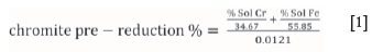
The soluble Cr (% Sol Cr) and Fe (% Sol Fe) in Equation [1] are extracted by reflux leaching of a pre-determined mass of the pre-reduced material with a hot sulphuric/phosphoric acid solution. The % Sol Cr in this aliquot is then established by means of the oxidation of the soluble Cr with potassium permanganate (KMnO4) and subsequent volumetric titration with ferrous ammonium sulphate ((NH4)2SO4) using diphenylamine sulphonate as an indicator. The % Sol Fe in the untreated aliquot is determined similarly, the only difference being that potassium dichromate (K2Cr2O7) is used as the titrant. In this analytical method, the % Sol Cr and % Sol Fe represent these metals in the metallized state, i.e. the zero oxidation state. However, the level of Cr and Fe metallization is not directly related to the total pre-reduction, since pre-reduction is more commonly related to the removal of oxygen (Barnes, Finn, and Algie, 1983). Therefore, a constant of 34.67 was calculated by dividing the molar mass of Cr by 1.5, and a constant of 55.85 for Fe was determined by dividing the molar mass of Fe by 1. These constant factors were derived from the stoichiometrically balanced chemical reaction equations, wherein 1.5 mole of CO (containing 1 mole of oxygen removed from the oxide) forms in the metallization reaction for 1 mole of Cr, and 1 mole of CO forms in the metallization reaction for 1 mole Fe (Barnes, Finn, and Algie, 1983). Lastly, the constant 0.0121 is a chromite reduction value for typical South African metallurgical-grade chromite ore, which is calculated from (total Cr/34.67 + total Fe/55.85)/100. Although this value is indicated as a constant in Equation [1], it was actually calculated for each analysis to compensate for different chromite compositions.
Material preparation prior to SEM analysis
In this study, both laboratory-prepared pellet mixtures, as well as industrially produced pre-reduced chromite ore pellets, were utilized to validate the new analytical technique. The laboratory-prepared mixture compositions were prepared in such a manner that the mixtures mimicked different pre-reduction levels, which ranged from 15, 30, and 45, to 60% pre-reduction. Three sets of these mixtures were prepared, with each set containing varying carbon contents, i.e. 1, 3, and 5 wt.% fixed carbon (FC). The laboratory-prepared mixtures, which consisted of FeCr, chromite ore, and anthracite were dry-milled to the particle size specifications for industrial pre-reduction feed material, i.e. 90% of the particles smaller than 75 urn (D90 = 75 um) (Neizel et al., 2013; Kleynhans et al., 2012). A Siebtechnik laboratory disc mill equipped with a tungsten carbide grinding chamber was used to avoid possible iron contamination. 50 g mixtures of raw materials were milled for 2 minutes to obtain the desired size specification. The particle size distribution was verified by laser diffraction particle size analysis utilizing a Malvern Mastersizer 2000. For this purpose, a much-diluted suspension of milled mixture was ultrasonicated for 60 seconds prior to the particle size measurement, in order to disperse the individual particles without the use of a chemical dispersant.
The laboratory-prepared pellet mixtures, as well as the industrially produced pre-reduced pellets that had already been milled in preparation for the determination of the level of pre-reduction, were mounted in resin and polished for cross-sectional SEM micrograph imagery. 1 g of the respective pellet mixtures was placed in 25 mm diameter mounting cups. The epoxy resin solution ratio was 100 g of resin to which 12 g of a slow-curing agent was added (50:6 mass ratio). The epoxy resin solution was stirred thoroughly in a plastic beaker for 3 minutes, then placed in a Speedivac vacuum degassing chamber model VDC 12, which ensures the elimination of air bubbles. A few drops of epoxy resin were added to each of the 1 g mixtures and mixed slowly to avoid stirring air into the mixture, but thoroughly to ensure homogenous mixtures. The mounting cups were then replaced in the vacuum chamber to remove any air bubbles. Additional epoxy resin was then added on top of these mixtures (over a label) to completely fill the 25 mm mounting cup. The mixtures in the mounting cups were then allowed to set overnight.
The epoxy resin-mounted samples were polished using an SS20 Spectrum System Grinder polisher, operated at an average speed of 300 r/min for grinding and 150 r/min for polishing. A 250 mm platinum 2 green cameo magnetic disc (comparable to 220-280 grit), a 250 mm platinum 4 red cameo magnetic disc (comparable to 600 grit), as well as 9, 3, and 1 um diamond paste polishing cloths were used. The two rough grits were operated by using continuous water flow as cleaner and lubricant, whereas diamond paste suspension poly lubricant was applied on the diamond paste cloths to obtain a smooth polished surface. Analytical grade ethanol was used to wipe the surfaces clean after polishing.
SEM image acquisition
Prior to SEM analysis, polished samples were rendered conductive by carbon coating in a Dentom vacuum DV-502A. An FEI QUANTA 250 FEG scanning electron microscope with an integrated OXFORD X-max EDS system, applying a backscattered electron compositional signal that operates with a 15 kV electron beam, at a working distance of 10 mm, 300 ns scan speed, and a magnification of 800x, was used to acquire SEM micrographs of the polished samples for further computational processing. Ten images were captured for every sample from random areas so that they were representative of the entire sample.
Image processing and analysis
All SEM micrographs were imported into and processed in MATLAB (MathWorks, 2017).
Results and discussion
Hypothesis
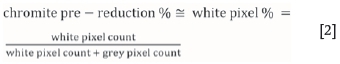
Elements with higher atomic numbers are indicated by lighter greyscale in SEM micrographs, while elements with lower atomic numbers are indicated by darker greyscale. For the composite chromite pellets considered in this paper, chromite ore particles that were not pre-reduced are therefore typically indicated as grey particles since they contain both heavy (Cr and Fe) and light elements (Si, Al). In contrast, metallized particles/droplets that form as a result of pre-reduction are typically indicated as white particles, consisting mostly of Fe and Cr. Kleynhans et al. (2012) presented SEM micrographs of an industrially pre-reduced chromite ore pellet indicating this principle. The EDS feature of the SEM-EDS used in this study was also used to confirm that particles appearing almost white in the polished samples contained mostly Fe and Cr. Considering the aforementioned, the basic hypothesis applied in the development of this new analytical technique was that the pixel count of white pixels (representing metallized particles), divided by the combined pixel count of white and grey (representing chromite particles) pixels can be directly related to the level of chromite pre-reduction determined by the current wet chemical method. This hypothesis can be mathematically expressed as:
Basic algorithm
The abovementioned basic approach was refined into a general algorithm consisting of several steps.
> The ten SEM micrograph images of a specific polished sample were cropped to the same size to remove the footer information (working distance, magnification) from each image.
> The ten cropped micrographs were stitched together into one image in order to ensure that image processing was not performed on a single micrograph, which might not be statistically representative of the overall sample.
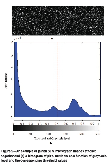
> The pixel count of white pixels in the stitched image was determined, which represented metallized particles according to the hypothesis. A typical example of the application of this methodology is presented in Figure 1. Figure 1a indicates an original greyscale SEM micrograph, while Figure 1b is a zoomed-in section for illustration purposes. The actual pixels in greyscale can be seen on this zoomed-in image. This greyscale map was then converted into a matrix in MATLAB containing the actual greyscale intensity number array that ranges from 0 to 255, with 0 being black and 255 indicating white, as shown in Figure 1c. This greyscale intensity number matrix was then converted into a binary matrix of black and white, which is indicated by 0 and 1, respectively in Figure 1d. This was achieved by applying a fixed threshold value of 0.98. In Figure 2, an example of an image consisting of ten stitched SEM micrographs is presented, together with a histogram indicating the number of pixels as a function of the greyscale numbers 0 to 255, as well as the correlating threshold values from 0 to 1. In practice, the fixed threshold value of 0.98 implies that the number of white pixels was regarded as the pixels occurring at greyscale values larger than the correlating threshold number of 0.98.
> SEM micrograph image acquisition is subject to minor artefacts, e.g. noise from the SEM detector. Therefore, noise filtering was applied on the white pixel areas to avoid random white pixels from contributing to the white pixel count. Any individual white pixel that was not next to another white pixel was discarded in this step.
> The number of greyscale pixels, representing the pre-reduced and non-pre-reduced chromite ore particles, was then determined. Two threshold values were determined for this purpose, with the number of greyscale pixels between these threshold values regarded as being representative. However, fixed threshold values could not be utilized, since the degree of metallization achieved influenced the range of greyscale levels observed for pre-reduced chromite particles. The criteria for the selection of the two threshold values can be explained by also considering the example presented in Figure 2. The epoxy resin in which the sample material was mounted and the carbon reductant (anthracite) formed part of the black pixel areas that are typically represented by greyscale colours correlating to a threshold value of < 0.2. Therefore, these pixels were not considered in this greyscale pixel count calculation. The range of appropriate greyscale was determined by varying the threshold value between 0.2 and 0.98 in steps of 0.02. This was performed in an iterative loop in MATLAB, which enabled the testing of all possible greyscale threshold ranges between 0.2 and 0.98. This approach is further explained in the method validation section.
> The last step in the method was to determine the white pixel percentage, as indicated in Equation [2].
Validation of the analytical technique with laboratory prepared pellets mixtures
In Figure 3, the correlation between the white pixel percentage (Equation [2]), determined with the algorithm described earlier and the chromite pre-reduction levels (%) of the laboratory-prepared pellet mixtures, are presented. It is evident from these results that there was a strong linear relationship (R2 = 0.998) between the white pixel percentage and the level of pre-reduction determined by the conventional wet chemical method.
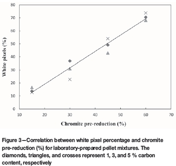
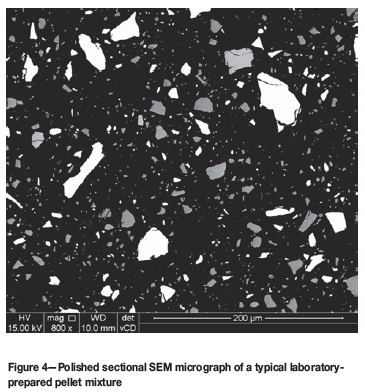
From Figure 3 it is clear that the method can be applied successfully to determine the level of chromite pre-reduction, at least for laboratory-prepared samples. However, these laboratory-prepared samples do not exactly represent the real-world samples. Firstly, the metallized particles represented by FeCr particles in these laboratory-prepared samples were totally liberated from the chromite particles, as is illustrated in Figure 4. Additionally, the greyscale intensity of the chromite particles was relatively constant, since these samples were not actually pre-reduced at elevated temperatures. This implies that the greyscale threshold ranges (step 'v' in the algorithm), which should be representative of the chromite particles, could have been chosen by checking the greyscale intensity numbers of a couple of chromite particles manually. Therefore, testing of the method on the laboratory-prepared samples was only the first step in the validation of the method.
Validation of the analytical technique with industrially pre-reduced pellets
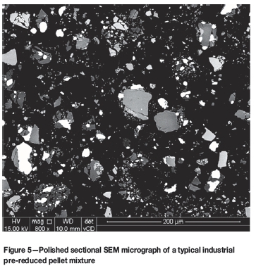
In Figure 5, a typical SEM micrograph of a mounted polished industrial pre-reduced pellet mixture is presented. In contrast to the laboratory-prepared mixture (Figure 4), most metallized particles (white areas) are associated with chromite grains, since the metallized particles actually form from the chromite during pre-reduction at elevated temperatures. In addition, the greyscale intensity of the chromite particles varies substantially. When Cr and Fe migrate from the chromite spinel to the metallized phase, the remaining chromite particle(s) will consist of a higher percentage of elements with lower atomic numbers and will consequently appear darker than the non-pre-reduced chromite particle(s). Therefore, the importance of selecting an appropriate greyscale range, between two matching threshold values, as indicated in Figure 2 and step 'v' of the algorithm, becomes apparent. These two threshold values cannot be selected manually, since the range of appropriate greyscale intensity that matches pre-reduced and non-pre-reduced chromite particles cannot be predicted.
Actual chromite pre-reduction levels up to 80% have been achieved commercially on an industrial scale. However, according to thermodynamic calculations Cr oxides reduce at higher temperatures than Fe oxides (Kleynhans et al., 2017a; Niemelã, Krogerus, and Oikarinen, 2004; Dawson and Edwards, 1986). Therefore, chromite pre-reduction above 60% is relatively uncommon in an industrial setting, since this would require elevated temperatures and exposure periods that become less feasible on a commercial scale. The industrial pre-reduced pellet mixtures received from the FeCr producer had pre-reduction levels varying between 38 and 50%. Figure 6 indicates the relationship between Cr and Fe metallization during chromite pre-reduction as a function of exposure time at 1 200°C (adapted from Dawson and Edwards, 1986). In this figure, the metallization and pre-reduction of the industrial pre-reduced pellet mixtures received are also indicated. It is evident that the increase in pre-reduction with time is not linear. However, for the purpose of the development of the alternative analytical technique, it was assumed that the level of pre-reduction over the pre-reduction percentage range of the industrial pre-reduced pellets received can be approximated by a straight-line correlation, as indicated by the dashed black linear line in Figure 6.
If the abovementioned assumption is valid, the white pixel percentage (according to Equation [2]) would be correlated to the chromite pre-reduction levels determined by the wet chemical technique (Equation [1]). This implies that the two threshold values determined in an iterative manner in step 'v' of the algorithm represent the optimal range of greyscale of the pre-reduced and non-pre-reduced chromite particles must stay constant to determine the white pixel percentage for the entire range of pre-reduction levels of the industrial pre-reduced pellet mixtures. From the results presented in Figure 7, it is evident that this is indeed the case. The chemically determined level of chromite pre-reduction (Equation [1]) of the industrial pellet mixtures correlated very well with the white pixel percentage calculated according to Equation 2 (R2 = 0.919) for industrial pellet mixtures originating from two different rotary kilns.
Possible industrial application of the method
The objective of this study was to investigate the possible development of a SEM image processing method that would enable the faster determination of chromite pre-reduction than the currently applied wet chemical method. From the results, it seems feasible that the developed method can be applied to determine chromite pre-reduction. However, two issues need to be addressed. Firstly, it needs to be established how the method can be applied to deliver quicker results, and secondly, the method needs to be validated over a wider range of pre-reduction levels than were considered in this study (38 to 50% pre-reduction).
Although not investigated as part of this study, it is suggested that actual pre-reduced pellets can be split into two halves, one of which can be polished relatively quickly. Industrial pre-reduced chromite pellets are strong enough to be polished in this manner (Kleynhans et al., 2012). These polished cross-sectional pellets can then be mounted in fit-for-purpose aluminium mounting stubs, with metal grub screws to hold the pellets in place. This would eliminate the need to carbon-coat the pellets, since such cross-sectional polished pellets would be conductive. SEM micrographs can then be obtained for these polished pellets without the necessity for setting the sample material in a resin matrix prior to polishing. In this study, only milled pre-reduced pellets were received, and this aspect of method development was therefore not considered in the current scope of work.
As indicated in Figure 6, the industrial pre-reduced material mixtures considered in this study were within a limited range of pre-reduction levels, i.e. 38 to 50 %. The results indicated that this range of pre-reduction could be linearly related to the white pixel percentage (Figure 7). However, according to the nonlinear increase in chromite pre-reduction presented in Figure 6, it might not be possible to accurately relate the white pixel percentage to the level of pre-reduction with only a single set of optimally determined greyscale threshold values (step 'v' in the algorithm). Therefore, it is proposed that reference standards are prepared to represent various ranges of pre-reduction. These standard samples could be prepared by splitting pellets into two halves, one of which could be analysed using the wet chemical method to determine pre-reduction, while the other half could be polished and mounted as described in the previous paragraph. An analysis of a pellet with an unknown level of pre-reduction should then be conducted simultaneously (and at the same SEM settings) with a set of standard pellets with known levels of pre-reduction. This would imply that a two-value threshold greyscale range (as indicated in step 'v' of the algorithm), which is applicable to the pre-reduction range covered by that specific set of standard pellets, would be determined. If the level of pre-reduction that was derived from the white pixel percentage of the unknown sample fell outside the range covered by the standards, then the unknown sample should be re-analysed with another set of standard samples that do represent the appropriate range.
Conclusions
As far as the authors could ascertain, the method described in this paper is the first SEM image processing method developed for the determination of chromite pre-reduction and described in the peer-reviewed public domain. In this method, the white pixel percentage (Equation [2]) is determined. A strong linear correlation (R2 = 0.919) between chromite pre-reduction (%) determined by wet chemical analysis and white pixel percentage was observed for industrially pre-reduced pellets from two different kilns. This demonstrated that the method can be applied in industry to determine chromite pre-reduction accurately. Adaptations of the investigated method, which include polishing of pre-reduced pellets without setting in epoxy resin and the preparation of standards to be analysed with an unknown sample, are proposed to make the method industrially viable. Such a method could significantly reduce the effective turnaround time for determination of chromite pre-reduction, which would result in improved metallurgical control of the pelletized chromite pre-reduction process.
References
Abubakre, O.K., Muriana, R.A., and Nwokike, P.N. 2007. Characterization and beneficiation of Anka chromite ore using magnetic separation process. Journal of Minerals and Materials Characterization and Engineering, vol. 6, no. 2. pp. 143-150. [ Links ]
Barnes, A.R., Finn, C.W.P., and Algie, S.H. 1983. The prereduction and smelting of chromite concentrate of low chromium-to-iron ratio. Journal of the South African Institute of Mining and Metallurgy, vol. 83, March. pp. 49-54. [ Links ]
Beukes, J.P., Dawson, N.F., and van Zyl, P.G. 2010. Theoretical and practical aspects of Cr(VI) in the South African ferrochrome industry. Journal of the Southern African Institute of Mining and Metallurgy, vol. 110, no. 12. pp. 743-750. [ Links ]
Beukes, J.P., van Zyl, P.G., and Ras, M. 2012. Treatment of Cr(VI)-containing wastes in the South African ferrochrome industry - a review of currently applied methods. Journal of the Southern African Institute of Mining and Metallurgy, vol. 112, no. 5. pp. 347-352. [ Links ]
Biermann, W., Cromarty, R.D., and Dawson, N.F. 2012. Economic modelling of a ferrochrome furnace. Journal of the Southern African Institute of Mining and Metallurgy, vol. 112, no. 4. pp. 301-308. [ Links ]
Botha, W. 2003. Ferrochrome production through the SRC process at Xstrata, Lydenburg Works. Journal of the South African Institute of Mining and Metallurgy, vol. 103, no. 6. pp. 373-389. [ Links ]
Cramer, L.A., Basson, J., and Nelson, L.R. 2004. The impact of platinum production from UG2 ore on ferrochrome production in South Africa. Journal of the South African Institute of Mining and Metallurgy, vol. 104, no. 9. pp. 517-527. [ Links ]
Daavittila, J., Honkaniemi, M., and Jokinen, P. 2004. The transformation of ferrochromium smelting technologies during the last decades. Journal of the South African Institute of Mining and Metallurgy, vol. 104, no. 9. pp. 541-549. [ Links ]
Dawson, N.F. and Edwards, R.I. 1986. Factors affecting the reduction rate of chromite. Proceedings of the 4th International Ferro-alloys Congress, Rio de Janeiro, Brazil, 31 August - 3 September. Finardi, J., Nascimento, J,O, and Homem de Melo, F.D. (eds). Associacao Brasileira dos Produtores de Ferro-Ligas-Abrafe, Sao Paulo. pp. 105-113. [ Links ]
ICDA. 2013. Statistical Bulletin 2013. International Chromium Development Association, Paris, France. [ Links ]
Jingzhong, H., Kewen, X., and Fan, Y. 2013. An approach to distinguish and detection in nodular cast iron metallographic analysis. Advances in Information Sciences and Service Sciences, vol. 5, no. 3. pp. 10-16. DOI:10.4156/AISS.vol5.issue3.2 [ Links ]
JoNES, R. 2014. http://www.pyrometallurgy.co.za/PyroSA/. Accessed 1 June 2014. [ Links ]
Kleynhans, E.L.J., Beukes, J.P., van Zyl, P.G., Kestens, P.H.I., and Langa, J.M. 2012. Unique challenges of clay binders in a pelletised chromite pre-reduction process. Minerals Engineering, vol. 34. pp. 55-62. DOI:10.1016/j.mineng.2012.03.021 [ Links ]
Kleynhans, E.L.J., Neizel, B.W., Beukes, J.P. and van Zyl, P.G. 2016. Utilisation of pre-oxidised ore in the pelletised chromite pre-reduction process. Minerals Engineering, vol. 92. pp. 114-124. DOI:10.1016/j.mineng.2016.03.005 [ Links ]
Kleynhans, E.L.J., Beukes, J.P., van Zyl, P.G., Bunt, R.J., Nkosi, N.S.B., and Venter, M. 2017a. The effect of carbonaceous reductant selection on chromite pre-reduction. Metallurgical and Materials Transactions B, vol. 48. pp. 827-840. DOI:10.1007/s11663-016-0878-4 [ Links ]
Kleynhans, E.L.J., Beukes, J.P., van Zyl, P.G., and Fick, J.I.J. 2017b. Techno-economic feasibility of a pre-oxidation process to enhance prereduction of chromite. Journal of the Southern African Institute of Mining and Metallurgy, vol. 117, no. 5. pp. 457-468. [ Links ]
MathWorks. 2014. http://www.mathworks.com, 2017. [Accessed 10 January 2017]. [ Links ]
McCullough, S., Hockaday, S., Johnson, C., and Barcza, N.A. 2010. Pre-reduction and smelting characteristics of Kazakhstan ore samples. Proceedings of the 12th International Ferroalloys Congress (INFACON XII), Helsinki, Finland. Vartiainen, A. (ed.). Outotec Oyj. pp. 249-262. [ Links ]
Murthy, Y.R., Tripathy, S.K., and Kumar, C.R. 2011. Chrome ore beneficiation challenges & opportunities - A review. Minerals Engineering, vol. 24, no. 5. pp. 375-380. DOI:10.1016/j.mineng.2010.12.001 [ Links ]
Naiker, O. 2007. The development and advantages of Xstrata's Premus Process. Proceedings of the 11th International Ferroalloys Congress (INFACONXI), New Delhi, India. Das, R.K. and Sundaresan, T.S. (eds.). Indian Ferro Alloys Producers Association. pp. 112-119. [ Links ]
Neizel, B.W., Beukes, J.P., van Zyl, P.G., and Dawson, N.F. 2013. Why is CaCO3 not used as an additive in the pelletised chromite pre-reduction process? Minerals Engineering, vol. 45. pp. 115-120. DOI:10.1016/j.mineng.2013.02.015 [ Links ]
Niayesh, M.J. and Fletcher, G.W. 1986. An assessment of smelting reduction processes in the production of Fe-Cr-C alloys. Proceedings of the 4th International Ferroalloys Congress (INFACON IV), Rio de Janeiro, Brazil, 31 August - 3 September. Finardi, J., Nascimento, J,O, and Homem de Melo, F.D. (eds.). Associacao Brasileira dos Produtores de Ferro-Ligas-Abrafe, Sao Paulo. pp. 115-123. [ Links ]
Niemelã, P., Krogerus, H., and Oikarinen, P. 2004. Formation, characterisation and utilisation of CO-gas formed in ferrochrome smelting. Proceedings of the 10th International Ferroalloys Congress (INFACON X), Cape Town, South Africa. South African Institute of Mining and Metallurgy, Johannesburg. pp. 68-77. [ Links ]
Riekkola-Vanhanen, M. 1999. Finnish expert report on best available techniques in ferrochromium production. Finnish Environmental Institute, Helsinki. pp. 1-50. [ Links ]
Takano, C., Zambrano, A.P., Nogueira, A.E.A., Mourao, M.B., and Iguchi, Y. 2007. Chromites reduction reaction mechanisms in carbon-chromites composite agglomerates at 1773 K. ISIJ International, vol. 47, no. 11. pp. 1585-1589. [ Links ] ♦
Paper received Jan. 2017
Revised paper received Mar. 2017

