


Services on Demand
Article
 English (pdf)
 Article in xml format
 Article references
Indicators

Related links
-
 Cited by Google
 -
 Similars in Google
Share

 Permalink
Journal of the Southern African Institute of Mining and Metallurgy
On-line version ISSN 2411-9717
Print version ISSN 2225-6253
J. S. Afr. Inst. Min. Metall. vol.117 n.11 Johannesburg Nov. 2017
http://dx.doi.org/10.17159/2411-9717/2017/v117n11a8
SULPHURIC ACID CONFERENCE
Computational model of large-capacity molten sulphur combustion spray efficacy and process efficiency
K. Brown; K. Bade; R. Schick
Spray Analysis and Research Services, Spraying System Company, Johannesburg, South Africa
SYNOPSIS
The use of precision spray injectors with advanced technology nozzles in the combustion of molten sulphur represents an active and growing field. The efficient combustion of large volumes of molten sulphur is a clear requirement in the phosphate industry. Spraying Systems Company, along with our industry partners, has conducted significant research in the laboratory as well as in full-scale industrial settings to arrive at optimized process solutions for this application.
Additionally, computational models have been developed to allow for the assessment and optimization of the sulphur combustion efficacy. Over the past decade there have been rapid advancements in computer and software technologies for simulation of complex applications. These strides have allowed for more complex simulations at reasonable cost, such as the design of spray injectors with stress analysis coupled with fluid dynamics and heat transfer.
This paper presents the results of a detailed spray injection modelling study demonstrating the scale-up of the spray solution as well as the 100% spray combustion requirement at these elevated sulphur flow capacities. Through the use of the models developed here, the sulphur combustion was improved beyond that which was possible using experimental results.
Keywords: molten sulphur combustion, atomization, injector modelling, computational fluid dynamics, CFD.
Introduction
Sulphur trioxide (SO3) is commonly used in the manufacture of sulphuric acid, oleum, chlorosulphonic acid, and other compounds. One method of obtaining SO3 gas for these processes is through the combustion of molten sulphur. The sulphur is liquefied and fed into the combustion chamber of a furnace through one or more injectors. These precision spray injectors are a critical component in the process. The injectors convert large quantities of molten sulphur into an atomized spray of sulphur particles. Control of the particle size is a critical factor in ensuring rapid vapourization and complete combustion within the combustion chamber. Unburned sulphur can deposit outside of the combustion zone, which results in process inefficiency and increased maintenance.
This work outlines the design considerations for a successful sulphur combustion injection system. The process details injector selection and empirical characterization of the injector. Additionally the injection system design is evaluated via computational fluid dynamics (CFD) to ensure the intended performance characteristics in the combustion chamber. These simulations address velocity profiles, temperature profiles, droplet tracking (devolitization), and other relevant characteristics of the application.
These injectors have a significant role to maintain over long time periods, in a harsh environment. The environment is characterized by extremely high temperatures and turbulent flow conditions. The injectors are fairly long and must remain in operation, maintenance-free, for up to 25 years. In order to optimize design and verify proper material selection, FSI is required to ensure performance and reliability for the design life of the injectors. This work outlines the design considerations for a successful sulphur combustion injection system. The process details injector design verification, based on the selection and preliminary design from previous work. These simulations address velocity profiles, temperature profiles, flow-induced vibration, and other relevant characteristics of the application.
Theoretical considerations
Atomization
Atomization is used in many spray applications to produce droplets with a high surface area to volume. Often this high ratio results in much more efficient use of the spray droplets in evaporative and/or combustion processes. In general, atomizers that cause the greatest physical interaction between the liquid and vapour are most effective.
Jet breakup
A liquid jet exhausted into air may be in a laminar or turbulent state. A laminar jet, which contains fluid particles that are travelling in parallel at the exit plane, may be created by utilizing a rounded inlet, having no mid-flow disturbances, and using a high-viscosity liquid. Turbulence in jets, which aids in jet breakup, may be encouraged through high flow velocities, large tube sizes, general surface roughness, rapid cross-sectional changes, and perturbations due to flow obstructions or vibrations. The Reynolds number (Re), which relates pressure and viscous forces, may be used to determine the likelihood of a flow to be laminar (low Re number) or turbulent (high Re number). The critical Reynolds number identifies where laminar flow will undergo the transition to turbulent flow. For pipe flow, the critical Reynolds number (Recrit) is approximately 2300. When a flow transitions from laminar to turbulent flow, the mechanisms governing jet breakup change and cause a decrease in jet breakup length.
Liquid sheet breakup
Fraser and Eisenklam (1953) defined and described three liquid sheet breakup regimes: rim, perforated sheet, and wave. Liquid surface tension and viscosity are the primary properties that determine which mode(s) of disintegration occur. Liquid sheet breakup through 'rim' disintegration often occurs with high-viscosity, high-surface-tension type liquids. In rim disintegration the liquid mass becomes thicker at the free edges, which ultimately form liquid threads that break up into large drops, whereas the internal area disintegrates and forms smaller drops.
In a 'perforated sheet' type breakup, many holes are developed in the liquid sheet. The edges of these holes become thicker as the holes grow and more fluid mass is combined at each hole edge. The holes continued to grow until they encounter other rims and coalesce. Drops of many different sizees are created. 'Wave' disintegration occurs when wave motions within the liquid sheet cause fluctuations with distinct wavelengths. These waves break up into whole or half wavelength sections and surface tension reforms the sections into strands. These strands then disintegrate into drops. Wave disintegration creates drops that vary the most in size.
Drop breakup
Atomization is the process by which a liquid jet is disintegrated by aerodynamic forces. These aerodynamic forces, which cause the liquid to form into small drops and often to further break down into droplets, are created by the velocity of the liquid jet relative to its surroundings. The breakdown of drops in a spray can be summarized with an internal/ external force assessment. The external aerodynamic pressure is balanced by the surface tension in order for the internal drop pressure to remain at a constant level, which it must do in order to sustain its drop size. In the event that the external forces are too large to be balanced though an increase in effective surface tension, the surface tension will be drastically increased through a decrease in the diameter of the drop (drop splitting). The process of drop splitting takes place until the surface tension pressure is large enough to counteract the aerodynamic drag pressure at all points on the drop's surface. The drop size at this equilibrium level is known as the critical drop size. The mechanisms that cause the breakup of drops can be further identified by considering some of the more complex aspects of 'real-world' conditions.
In turbulent flow fields the relative velocity between a drop and the surrounding gas will be very high, either locally or on a global scale. The turbulent field will impart a dynamic force on the drop, which will determine the largest drop size that can exist in equilibrium due to the energy in the most disruptive turbulence scales (E). With dynamic turbulent forces present, the Weber number, which for low-viscosity liquids relates the deforming external pressure forces to the reforming surface tension forces of a liquid drop in air, can be evaluated for low-viscosity liquids and used to estimate the maximum drop size based on these scales.
In high-viscosity (low Reynolds number) flow fields, where dynamic forces no longer control breakup, the surface tension forces and viscous forces work to deform and reform liquid drops. It is generally very difficult to atomize liquids that have a high liquid-to-air viscosity ratio. In these high-viscosity flows, variations in the air viscosity make little difference to the atomization process. Also, high-viscosity liquid-phase spray material delays the breakup of drops and impedes atomization, which is why more aggressive methods, such as air-blast atomization, are often used.
In practice
Hydraulic nozzles
Hydraulic nozzles are pressure-driven nozzles that spray a single fluid. Many different types of hydraulic nozzle designs exist, which aim to produce a variety of spray patterns from a continuous stream to a dispersed spray. These nozzles rely solely upon high liquid-to-gas relative velocities at exhaustion to achieve atomization. Liquids with low viscosity and high velocities atomize more readily; therefore hydraulic nozzles may suffice.
Two-fluid (pneumatic) nozzles
The mixing of two fluids (usually one liquid phase and one gaseous phase) by a nozzle may be accomplished either internally or externally to the nozzle body. In an internally mixing nozzle, the liquid flow and gas flow interact upstream of the final discharge orifice. In this case, the mixture exits as a single mixed flow, which widens with a reduced liquid flow velocity due to the pressurized gas. An internally mixing nozzle is optimum for high-viscosity fluids in a low flow rate application, since the breakup of this type of flow is more difficult. However, the flow rate of each fluid is then coupled, and to reach a desired operating condition, both flow rates must be tuned.
In an externally mixing nozzle the two fluid flows do not interact until after exiting the final nozzle orifice. These nozzle types may be designed to generate various spray characteristics depending on the atomizing air pressure. However, due to the uncoupling of the two fluid streams, these nozzles are much less efficient in their use of the atomizer fluid. Also, externally mixing nozzles do not offer the possibility of the liquid flow to 'back up' into the gas flow orifice; this may be a benefit in certain processes.
Fluid considerations
The spray angle of a nozzle represents the expected coverage of a spray exiting from the nozzle. The theoretical spray angle (the angle in the near-exit region) will diminish at larger downstream distances. Higher viscosity liquids will tend to form less divergent sprays, whereas lower viscosity liquid sprays disperse more easily into a wide spray. The surface tension of the spraying liquid has a direct effect on the spray angle. Liquids with lower surface tensions form wider sprays.
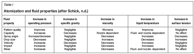
The liquid properties such as (dynamic) viscosity, density, and surface tension directly affect and determine the spray type and quality that is created at a given operating condition. Liquid viscosity is representative of the propensity of a fluid to take the shape of its surroundings. A high-viscosity fluid (syrup-like) will resist conforming to its surroundings and will move very slowly. The liquid viscosity directly affects the pattern at which a liquid will spray. High-viscosity liquids require a higher pressure to spray due to their resistance to flow and will naturally form narrower sprays. Liquid density is directly proportional to the capacity of a spray. Density represents the mass-to-volume ratio for a liquid and therefore spraying a high-density liquid at a given velocity will result in a higher capacity spray. Liquid surface tension is a property representative of the internal force that holds a liquid together. This internal tension affects the liquid spray's minimum operating pressure, spray angle, and drop size. A higher surface tension will require a higher operating pressure, reduce the spray angle, and produce larger drop sizes.
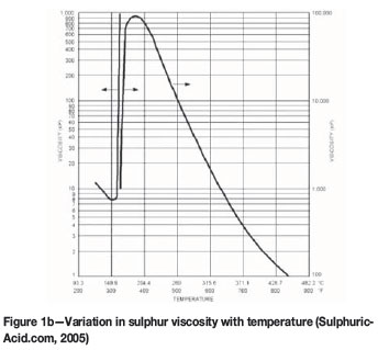
The properties of molten sulphur are highly temperature-dependent, and thus the temperature of the liquid feed through the injector is required to be tightly controlled. This is achieved by means of steam-jacketed lining. Steam must be continually circulated to maintain the desired physical properties of the molten sulphur and corresponding spray performance. Table I lists representative liquid properties and their general effects. Figures 1a and 1b detail the temperature-dependent properties of sulphur density and viscosity.

Injector property considerations
Nozzle construction materials may vary from lightweight plastics to case-hardened metals. The material that is most suited to an application depends directly on the spray substance, spray environment (corrosive, heated, etc.), and desired spray characteristics.
Typical furnace temperatures are in the range of 900-1500°C. In order to function properly the injector must withstand the external temperatures, internal temperatures, and exposure to process fluids and internal forces. There are many readily available heat-resistant injector materials such as type 310, 304, 316, or 309 stainless steel or similar materials; the combination of material and design must be evaluated and optimized for each application.
Injector design
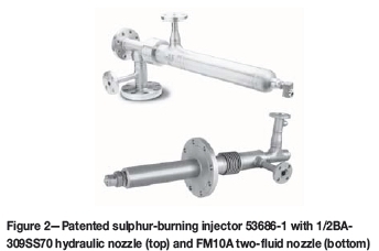
Spraying Systems' patented design of an 'Enhanced efficiency nozzle for use in molten sulfur combustion' provides a refined solution to the sulphur feed injection process. There are options for hydraulic and two-fluid (pneumatic) injection of molten sulphur. The use of an unobstructed feed path for cleaning provides for easy maintenance with a uniform distribution of small to medium drop size throughout a range of flow rates. Where large turndown ratios are required, a transversely intersecting steam (or gas) flow greatly improves the ability to maintain efficacy and efficiency of the combustion process by tightly controlling the atomization of the molten feed. In addition to these features, the unit allows for thermal expansion and withstands the temperature loading in the burner without bending. Steam-jacketed designs allow for tight control of the molten sulphur temperature and related rheological fluid properties. Injectors can be manufactured to specified lengths in various materials, in compliance with ASME B31 3-2010 standards. Figure 2 provides a representation each type of design configuration.
The Spraying Systems sulphur-burning nozzles offer many advantages, some of which are:
> Uniform spray distribution to fit exact coverage with maximum atomization for a given amount of flow
> Controlled spray velocity
> Each injector nozzle is custom-designed to exact specifications to maximize performance
> Ability to provide good atomization at relatively low AP (30-40 psi liquid; 50-60 psi steam)
> Large non-clogging passages
> Rugged, durable construction
> Ongoing research for improved product
> Designs are patent-protected
> 25 years of continuous service.
Experimental testing
Test set-up and data acquisition
For drop sizing, the nozzle was mounted on a fixed platform 72 inches (1.82 m) from the floor. A fixed assembly held the nozzle in place and data was acquired at 36 inches (0.91 m) downstream of the nozzle exit. Drop size and velocity data was collected at various operating conditions.
A two-dimensional Artium Technologies PDI-200MD (Schick, n.d.; Sulphuric-Acid.com, 2005; ANSYS, 2010; Fluent Inc, 2007) system was used to acquire drop size and velocity measurements. The solid-state laser systems (green 532 nm and red 660 nm) used in the PDI-200MD are Class 3B lasers and provide 50-60 mW of power per beam. The lasers were operated at an adequate power setting to overcome interference due to spray density.
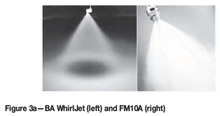
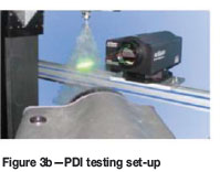
The transmitter and receiver were mounted on a rail assembly with rotary plates; a 40° forward scatter collection angle was used. For this particular test, the choice of lenses was 1000 mm for the transmitter and 1000 mm for the receiver unit. This resulted in an ideal size range of about 4.0-1638 µm diameter drops. The optical set-up was used to ensure acquisition of the full range of drop sizes while maintaining good measurement resolution. The particular range used for these tests was determined by a preliminary test run where the DV0.5and the overall droplet distribution were examined. For each test point, a total of 10 000 samples were acquired. The experimental set-up can be seen in Figures 3a and 3b.
The DV0.1, DV0.5, D32, and DV0.9 diameters were used to evaluate the drop size data. This drop size terminology is as follows.
> DV0.1 is a value where 10% of the total volume (or mass) of liquid sprayed is made up of drops with diameters smaller or equal to this value
> D32: Sauter mean diameter (also known as SMD) is a means of expressing the fineness of a spray in terms of the surface area produced by the spray. SMD is the diameter of a drop having the same volume-to-surface area ratio as the total volume of all the drops to the total surface area of all the drops
> DV0.5: volume median diameter (also known as VMD or MVD) is a means of expressing drop size in terms of the volume of liquid sprayed. The VMD is a value where 50% of the total volume (or mass) of liquid sprayed is made up of drops with diameters equal to or smaller than the median value. This diameter is used to compare the change in average drop size between test conditions
> DV0.9 is a value where 90% of the total volume (or mass) of liquid sprayed is made up of drops with diameters smaller or equal to this value.
By analysing drop size based on these standardized drop statistics it is possible to objectively characterize the quality and effectiveness of this atomizing nozzle for the prescribed application.
Test fluids and equipment
All testing was conducted using water. Liquid flow to the system was supplied using a high-volume pump at full capacity. The liquid flow rate to the atomizer was monitored with a MicroMotion D6 flow meter and controlled with a large bleed-off valve. The MicroMotion flow meter is a Coriolis mass flow meter that measures the density of the fluid to determine the volume flow. The meter is accurate to ±0.4% of reading. Liquid pressures were monitored upstream of the nozzle with 0-1.73 MPa class 3A pressure gauges. Photographs of the set-up and operation of the test nozzle are shown in Figures 3a and 3b.
Test conditions
Data was acquired for multiple flow conditions. These tests involved the interaction of various liquid pressure levels and flow rates for five flow capacities (see Figures 5 and 6 in the Results section) in order to characterize the nozzle's spray at various testing conditions and determine optimal operating conditions for this application.

Numerical simulations
CFD methods
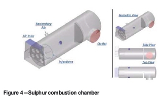
Computational fluid dynamics (CFD) is a numerical method used to solve fluid flow problems. Today's CFD uses extremely large numbers of calculations to simulate the behaviour of fluids in complex environments and geometries. Within the computational region, CFD solves the Navier-Stokes equations to obtain velocity, pressure, temperature, and other parameters that may be required. CFD recently became a popular design and optimization tool with the help of commercially available software and advanced computer technology. The CFD simulation problem called for the assessment of liquid sulphur combustion inside the combustion chamber. The sulphur is atomized via spray nozzles in order for efficient burn-off.
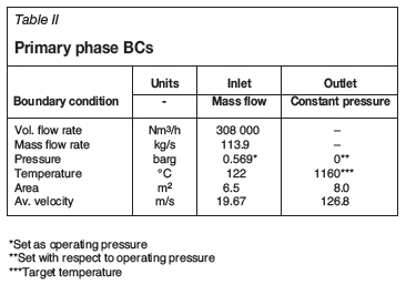
The commercially available CFD package ANSYS FLUENT (version 12.1) was used for the simulation of sulphur combustion with air as an oxidizer. Air and combustion gases inside the horizontal combustion chamber were set as primary phase flow (Eulerian approach). The primary phase used coupled models (momentum, turbulence, energy, species mixing, and combustion), which required boundary conditions (BCs). Table II shows the BCs for the primary phase. This problem consisted of inlet BC and outlet BC, set as 'mass flow rate inlet' and 'constant pressure outlet' respectively. At the inlet a mixture of gas with oxygen and nitrogen (air) was employed. These had to be separate since oxygen is needed in the combustion process.
The sulphur injection was set as secondary phase (Lagrangian approach) where the inlet BCs are based on spray injection parameters as determined empirically. The Lagrangian particles were set as 'combusting'. Table III shows the injection BCs of the injection nozzle. The Lagrangian particles were tracked using a discrete phase model (DPM). During computation, heat and mass transfer were coupled between primary and secondary phases.
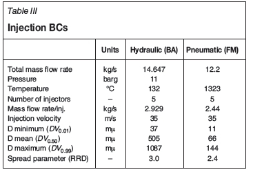
The sulphur injection was set as secondary phase (Lagrangian approach) where its inlet BCs are based on spray injection parameters as determined empirically. The Lagrangian particles were set as 'combusting'. Table III shows the injection BCs of the injection nozzle. The Lagrangian particles were tracked using a DPM. During computation, heat and mass transfer were coupled between primary and secondary phases.
To generate the computation domain (mesh) for the combustion chamber shown in Figure 4, Gambit (version 2. 3.16) was utilized. The mesh consisted of 3 986 432 million mixed cells. Due to its size and modelling complexity, the simulation required significant computer power and processing time.
The primary phase, which consisted of the gas mixture, was mainly dependent on temperature as large temperature variations were expected. The gas was treated as an incompressible ideal gas (no pressure variation, whereas operating pressure is used in the Ideal Gas Law), with physical properties such as density, heat capacity, viscosity, thermal conductivity etc. set to be dependent on temperature. The operating pressure was set based on air inlet pressure (see Table II). The walls had a common (standard) set-up, with no slip, adiabatic (insulated), and reflect for the combusting particles.
For the combustion study, a species mixing model was used to accommodate combustion with oxygen from air. The evaporation and combustion of the liquid sulphur, using dispersed-phase modelling capability, was employed to compute coupled gas flow and liquid spray physics as mentioned previously. The mixture fraction/PDF equilibrium chemistry model was used to predict the combustion of the vapourized fuel. This approach allows the simulation of combustion by solving a transport equation for a single conserved scalar, the mixture fraction. Property data for the species is accessed through a chemical database and interaction is modelled using a p-PDF.
The basis of the non-premixed modelling approach is that under a certain set of simplifying assumptions, the instantaneous thermochemical state of the fluid is related to a conserved scalar quantity known as the mixture fraction, /. The mixture fraction can be written in terms of the atomic mass fraction (ANSYS, 2010):
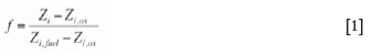
where Zi is the elemental mass fraction for element i. The subscripts 'ox' and 'fuel' refer to the values at the oxidizer and fuel stream inlet respectively.
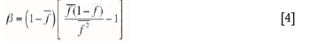
The p-PDF shape is given by Equations [2]-[4].
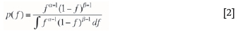
where
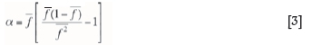
and
Radiation was modeled with the P-1 radiation model. This is a simplified radiation model that is based on the more general P-N model, which is based on the expansion of the radiation intensity I into an orthogonal series of spherical harmonics (ANSYS, 2010). For combustion applications where the optical thickness is large, the P-1 model works reasonably well. In addition, the P-1 model can easily be applied to complicated geometries with curvilinear coordinates (ANSYS, 2010).
Results
Experimental results
The results of the PDI measurements provide a representative characterization of the atomizer effectiveness at the 36-inch downstream investigation location. The results are provided in Table III. The Sauter mean diameter (Z>32) as well as other representative diameter statistics based on the volume flow are presented. These results allow the qualitative evaluation of the dependence of drop size on the liquid flow rate and pressure.
CFD results
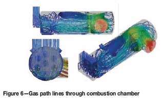
The CFD results provide great insight into the mixing mechanisms and spray interactions in complex environments such as combustion. The boundary conditions, as described above, mimic the intended real-world operation of this sulphur feed injection nozzle and provided quality inputs for numerical analyses. These CFD calculations, based on the k-epsilon turbulence model, were allowed to run through hundreds of iterations until a steady-state solution was realized. This solution was deemed acceptable when the calculation residuals (changes in the results from one iteration to the next) were negligibly low and good convergence was achieved. Figure 6 illustrates the path lines of the gas flow traced through the combustion chamber. This provides a preliminary assessment of the injection locations, which due to the relative momentum of the gas stream, influence the droplet trajectories and particle tracks. An increased velocity profile is apparent at the six entry points of air into the chamber. This will affect the droplets, pulling drops towards the base of the combustion chamber. If this effect is large, there is potential for wall impingement, resulting in wall damage and reduced efficiency of the process.
Additionally, the effects of the secondary air on the general flow can be assessed. The secondary air has a significant effect on the top three injected sprays. This secondary air is poorly distributed through the combustion chamber.
The velocity profile demonstrates the high velocity magnitude of both fluids as they enter the mixing and combustion region. As would be expected, there are very low velocity regions in the combustion chamber near the walls and the mixed flow has a fairly uniform mid-level velocity profile as it moves through the primary combustion area (see Figure 6).
The combustion was considered through with a non-premixed modelling approach. The property data for the species was accessed through a chemical database and the interaction was modelled using a p-PDF. The results of the combustion based on species contents are shown in Figure 7.

The primary focus of this study was to verify that the sulphur injection droplets were fully devolatilized prior to the exit of the combustion chamber. Failure to achieve this could lead to downstream damage and increased cost of operations. From Figure 7, it is evident that sulphur combustion is complete prior to the baffle wall. From the injection planes (the right-hand side of Figure 7), it is evident that the oxygen from the secondary air results in faster combustion rates at the top of the combustion chamber compared to the lower regions. This trend is mirrored by the oxygen profiles within the combustion chamber.
The combustion of the sulphur injections can also be examined through visualizing the spray emitted from the injectors. An initial DPM concentration (DPMC) value was used to define the spray plume boundary (SPB) and visualize the spray region, as shown in Figure 8. The isosurface of DPMC was based on matching peaks of CFD DPMC value and experimental volume flux at measured with the PDI. To obtain the cut-off DPMC, the cut-off volume flux point at about 0.002 cm3/cm2/s was matched with 0.001 kg/m3.
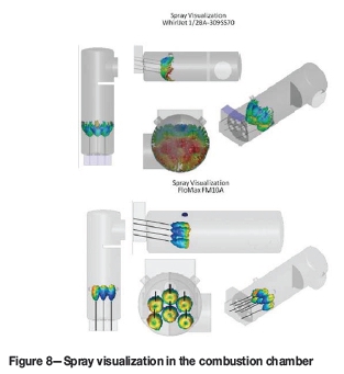
With the hydraulic atomizer, there is some potential for droplet impingement with the base of the spray chamber (this region is highlighted in red). From the top view (shown on the left-hand side of Figure 8), there is no evidence of wall impingement along the sides of the combustion chamber; however, sulphur spray occupies the full diameter of the combustion chamber. This would indicate that the spray angle of the injector is optimal for the application. This is fully mitigated in the case of the two-fluid atomizer (shown on the right). The FloMax two-fluid atomizer is able to better control the drop size of the molten injection. This allows for faster combustion and mitigates the risk of contact with the walls of the combustion chamber.
The resulting temperature profiles for the combustion chamber were examined. The temperature profiles are displayed in Figure 9. Temperatures were not uniform from top to bottom. This is due primarily to the fact that the secondary air adds cooler air and also acts as an additional source of oxygen to improve the combustion. The rate of combustion is slightly higher towards the top of the combustion chamber.
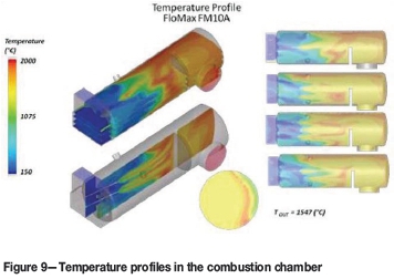
Temperatures at the outlet were found to be around 1400°C. This is slightly above the measured values of 1100-1200°C. This error could be improved with a more complex combustion model and more complex radiation model. However, the simulation does prove to be a reasonable assessment of the sulphur combustion application.
Structural considerations
CFD and FEA analysis was performed to determine temperature, pressure, and velocity flow around the injectors. The results of this work are shown in Figures 10-13. Temperatures were determined to peak at 570°C, which is within the expected range for this application. The main body of the injector has a well-controlled temperature range, due to the recirculating steam design. The highest temperature occurs at the outer edge of the injector tip.
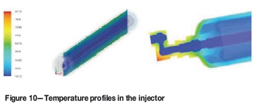

The thermal load on the lance has multiple sources. Heat transfer from the combustion process and gas stream acts on the outer surface of the injector. The recirculating steam supplies further heat from the internal chamber of the steam-jacketed injector. The final contribution to the thermal load is from the molten sulphur feed. The maximum temperature of the injector of 570°C is well below the melting point for stainless steel.
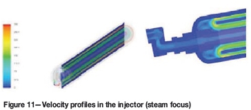
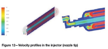
Velocity results are shown in Figures 11-12. Multiple scales are used to investigate the steam flow initially, and in the injector tip. The velocity in the steam line far exceeds the flow of the molten sulphur through the nozzle. Owing to the high viscosity of the molten sulphur, the velocity at the exit orifice is 25 m/s. This is as expected for the injector style and operating conditions.
The pressure distribution through the injector is shown in Figure 13. Again, due to the high viscosity of the molten sulphur, there is a significant pressure drop across the injector.
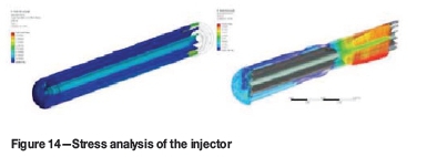
The cantilevered injector was modelled using a fixed surface at the flange location. The pressures were accounted for: from the combustion chamber, steam jacket, and internal sulphur flow. The maximum stress concentration is located at the base of the lance, near the flange. The stress results are contained in Figure 14. The maximum stress, of 271 kilopounds per square inch (ksi)1 exceeds the yield strength of stainless steel of 33 ksi. It is evident that supports will be required for this application.
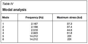
Modal analysis was performed to determine the dynamic natural response of our model when subjected to free vibration. Overall mass and stiffness were used to determine the various periods at which the injector will naturally resonate, which could potentially lead to failure. The natural frequency was compared to the vortex shedding frequency determined during failure analysis.
Six modes were used to analyse vibration in the injector, although the first is the most probable vibration mode. The six vibration modes are: (1) side-to-side vibration, (2) up and down vibration, (3) side-by-side vibration along a fixed point at the centre of the lance, (4) up and down vibration along a fixed point at the centre of the lance, (5) side-by-side vibration along two fixed points in the lance, and (6) up and down vibration along two fixed points in the lance. The results of the modal analysis are contained in Table IV.
Discussion and conclusions
Engineering optimization of injectors
The optimal nozzle design for sulphur feed injection for this combustion application incorporates the Spraying Systems patented nozzle, optimized based on the results of tests presented in this report. The Spraying Systems nozzle can provide the necessary spray characteristics with minimal wall impingement and full combustion of injected sulphur. Drop sizes ranging from less than 37 µm to greater than 1087 µm were created at the selected operating conditions.
The results of the CFD analyses provide insight into the internal mixing mechanics of the sulphur combustion process and allow for better optimization. High-accuracy, steady-state simulations of the nozzle gave a better understanding of the governing mixing forces, and their relative effects on the internal mixing and combustion is evident. It is clear from these models (see Figures 6-9) that the injected molten sulphur will thoroughly combust, without interactions leading to increased operational costs or equipment damage.
The hydraulic and two-fluid atomizers were compared to provide a general design aid. Multiple performance variations were identified through the empirical and simulation investigations. The in-depth analysis of these results, and those from previous tests, provides an experimental, computational, and analytical basis for the optimization of sulphur combustion injectors. With improved knowledge of the internal mechanics and the external spray pattern, the performance of the nozzle at these operating conditions can be optimized very effectively.
A sulphur-burning injector was analysed to determine its suitability for use in in a combustion chamber at normal operating conditions. An optimized injector design was incorporated into a lance. Due to the length requirement of the injector, structural analysis was required to determine suitability for long-term, maintenance-free service. A full analysis was performed for the injector; including fluid flow analysis, structural analysis, and one-way fluid structure analysis (Figures 10-14).
Acknowledgement
The authors thank Mr. Wojciech Kalata of Spraying Systems Co. for his assistance with this project.
References
ANSYS. 2010. Fluent Theory Guide, Release 13.0. November 2010. [ Links ]
Bachalo, W.D. 1994. Experimental methods in multiphase flows. International Journal of Multiphase Flow, vol. 20 (suppl.). pp. 261-295. [ Links ]
BACHALO, W.D. 1980. A method for measuring the size and velocity of spheres by dual beam light scatter interferometry. Applied Optics, vol. 19, no. 3. pp. 363-370 [ Links ]
Bachalo, W.D. and Mauser, M.J. 1985. Spray drop size and velocity measurements using the phase/doppler particle analyzer. Proceedings of the 3rd International Conference on Liquid Atomisation and Spray Systems, Imperial College, London, 8-10 July 1985, vol. 2. pp. VC/2/1-12. [ Links ]
Bachalo, W.D. and Mauser, M.J. 1984. Phase/doppler spray analyzer for simultaneous measurement of drop size and velocity distribution. Optical Engineering, vol. 23, no. 4. pp. 583-590. [ Links ]
BLEVINS, R.D. 1990. Flow Induced Vibration. Krieger Publishing, Malabar, FL. Fluent Inc. 2007. FLUENT 6.3 User's Guide. [ Links ]
Lefebvre, A.W. Atomization and Sprays. Hemisphere Publishing. pp. 1-78. [ Links ]
Naudascher, E. and Rockwell, D. 1994. Flow Induced Vibrations: An Engineering Guide. Dover Publications [ Links ]
Schick, R.J. Not dated. A guide to drop size for engineers. Spraying Systems Co., Bulletin 459. Wheaton, IL. [ Links ]
SuLPHURic-AciD.com 2005. Properties of sulphur. http://www.sulphuric-acid.com/TechManual/Properties/properties_sulphur.htm ♦ [ Links ]

