


Servicios Personalizados
Articulo
 Inglés (pdf)
 Articulo en XML
 Referencias del artículo
Indicadores

Links relacionados
-
 Citado por Google
 -
 Similares en Google
Compartir

 Permalink
Journal of the Southern African Institute of Mining and Metallurgy
versión On-line ISSN 2411-9717
versión impresa ISSN 2225-6253
J. S. Afr. Inst. Min. Metall. vol.117 no.11 Johannesburg nov. 2017
http://dx.doi.org/10.17159/2411-9717/2017/v117n11a4
SULPHURIC ACID CONFERENCE
Two years of operation at Kansanshi's sulphuric acid plant
B. MumbaI; D. LourieII; P. NgambiI
IFirst Quantum Minerals Ltd, Zambia
IIDKL Engineering Inc., Canada
SYNOPSIS
Kansanshi Mining plc's copper smelter in Solwezi, Zambia started production in March 2015 and has now been operating for over two years. The sulphuric acid plant has performed well during this period with an average availability of about 93%. However, issues arose in the plant which were not evident during the design phase and became evident only after operation for an extended period, predominatly around the converter. Other areas where operating issues were encountered were wet electrostatic precipitator performance, blower power consumption, converter bed temperature profile, and converter internal duct reinforcement. This paper provides details on the issues and the solutions implemented.
Keywords: sulphuric acid plant, converter bed temperature, wet electrostatic precipitator, acid mist capture, preheater.
Introduction
In March 2015 Kansanshi Mining plc commenced operation of a greenfield copper smelter near Solwezi, Zambia. The smelter is designed to treat 1.2 Mt of copper concentrate per year. Concentrate is smelted in an Isasmelt furnace, and the matte is subsequently converted to blister copper in Peirce-Smith converters (PSCs). The off-gases from the Isasmelt furnace and the PSCs are directed to wet gas cleaning systems and then to a contact sulphuric acid plant (SAP).
Acid plant operation and performance
Overall, the SAP has performed well, allowing rapid ramp-up of the smelter to its design capacity of 1.2 Mt/a. The sophisticated control philosophy for the acid plant-smelter interface has allowed for relatively trouble-free operation with the smelter. The acid plant can easily handle transitions in gas flow and SO2 concentrations resulting from the operation of PSCs. The goal for the future is to maintain the high availability of the acid plant through improvements in maintenance. There is also a desire to maximize acid plant throughput to maximize production of both copper and acid. While the operation and performance of the acid plant has been nearly trouble-free, some of the more interesting issues that we overcame are presented later in the paper.
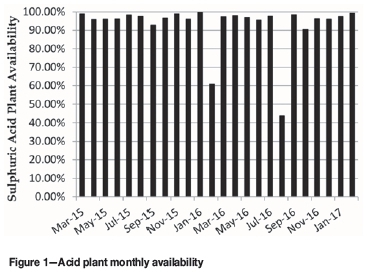
Plant availability
Availability of the plant has exceeded 93.1% on average, with over 99% availability in the best month (see Figure 1). KMP's definition of availability is the time that the acid plant is ready and available to receive gas from either the Isasmelt furnace or from the PSCs. Downtime due to site power outages is not included in acid plant availability.
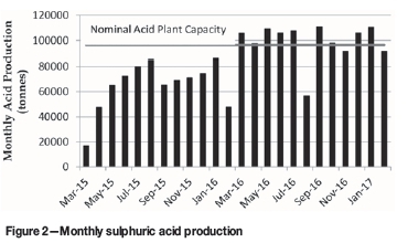
Acid production
The maximum daily production achieved to date is 4077 t.
Figure 2 shows the steady ramp-up of smelter throughput and the corresponding increase in acid production. For the months of March through to February 2017, acid production exceeded nominal design capacity for the plant. From September 2015 to January 2016 concentrate treatement, and therefore acid production, was limited due to lack of concentrate. Production was low in February 2016 due to the planned shutdown to repair the SAP converter, and in August 2016 due to a shutdown to repair damaged bricking in the Isasmelt furnace.
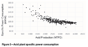
Electrical power consumption
Specific power consumption for the acid plant when the production rate is above 3500 t/d is less than 100 KWh/t of acid produced, with some days in the low 90s (see Figure 3). SAP electrical power consumption figures include all process drives in the gas cleaning, contact, strong acid, cooling water, and effluent handling areas.
Converter
The converter is 17.5 m diameter with a 7.2 m diameter central core that houses two internal gas-to-gas heat exchangers. The central core is also used to direct gases into the converter via ducts in the core.
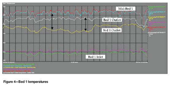
Converter bed temperature profile
The converter was designed with multiple temperature measurements in the catalyst beds. Beds 1 and 4 are equipped with two inlet, two mid-bed, and two outlet temperature measurements located 180° apart. Beds 2 and 3 are equipped with two inlet and two outlet temperature measurements only. A mid-bed thermowell is provided but a thermocouple is not installed.
Accurate temperature measurements are important for the proper operation of the converter to maximize conversion and to prevent damage to the catalyst and converter, particularly in bed 1. In a large converter, multiple temperature measurements also provide a better idea of the temperature profile across the catalyst bed.
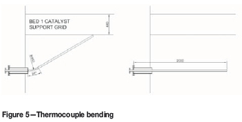
Since the startup of the plant the bed 1 outlet temperature was always lower than the mid-bed temperature reading by up to 50-60°C. Also, there was a significant difference between the two outlet temperatures by up to 20°C (see Figure 4). Initially the cause was believed to be the placement of the thermowells in the gas space rather than in the catalyst bed itself.
This theory was proved by bending one bed 1 outlet thermocouple so that the end was closer to the bottom of the bed (see Figure 5). The result was a 20°C higher temperature reading, but the outlet temperature was still less than the mid-bed temperature reading. The conclusion is that thermocouples in the gas space do not provide a true temperature reading.
Based on the temperature observations, the thermocouples were relocated during the February shutdown to provide more reliable readings. Furthermore, additional thermocouples were installed in the bed 1 inlet and outlet to obtain a better idea of the temperature profile across the bed. The additional temperature readings in bed 1 have helped to diagnose previous operating problems with one side of the catalyst bed going cold. A smelter outage in August 2016 provided an opportunity to enter the converter for an inspection. It was discovered that the catalyst in bed 1 was blown around, with a deep trench formed around the outside wall (see Figure 6).
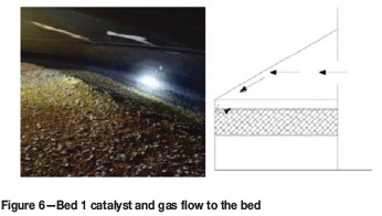
When the gas exits the windows in the central core it travels across the top of the bed and impacts on the sloping roof, which directs the gas to the outside wall. The gas is deflected down into the catalyst bed with a high enough velocity so that the catalyst and hold-down rings are blown to the centre of the bed, forming the trough around the perimeter.
The top layer of catalyst and ceramic rings were screened to separate them and a small amount of makeup catalyst was added. The catalyst bed was levelled and ceramic balls instead of ceramic rings were used as a hold-down layer around the circumference of the bed.
When the plant was restarted there was a surprising benefit of levelling the bed and eliminating the trough. All temperature readings (six in total) at the bed inlet started to indicate within 5°C of each other, compared to a 10-15°C difference before the shutdown. The same improvement occurred with the bed outlet temperatures. The temperature readings now indicate a more even temperature and gas distribution across the bed, indicating that the the perimeter trough was the main factor in poor temperature distribution.
The August shutdown also revealed that the converter is subject to high-temperature scaling, like so many other stainless steel converters in the industry. During the shutdown the scale was cleaned from the bed outlets, heat exchangers, and gas ducts.
Bed 4 bypass
Soon after startup, problems were encountered in controlling the bed 4 inlet temperature. The design inlet temperature was 410°C but during operation the minimum temperature that could be achieved was about 430-440°C. The bypass damper around the internal hot reheat exchanger was always 100% open, indicating that possibly the bypass was either too small or too restrictive in terms of pressure drop.
To complicate the understanding of the issue, the SO2 emissions from the stack were relatively low, even though the bed inlet temperature was too high and often higher than the bed outlet temperature.
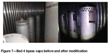
Inside the internal hot reheat exchanger the bypass distributor consisted of 20 pipes with distributor caps to distribute the gas evenly and ensure good mixing of the hot gas and the colder bypass gas. It was determined that the distribution caps were too restrictive and did not allow sufficient cold gas to be bypassed with the available pressure drop. The solution was to increase the size of the openings in the distribution caps (see Figure 7).
The other issue in the discrepancy between the bed temperatures and SO2 emission was not related to the bypass issue; it was the placement of the bed inlet thermocouples. Normally the bed inlet thermocouples are placed at the top of the catalyst bed between the hold-down layer of quartz/ceramic and the catalyst. In this case the thermocouples were placed in the gas space just below the division plate with bed 2 (see Figure 8). It is believed that the bed 4 inlet thermocouples were measuring higher temperatures due to the radiation from the hotter division plate (bed 2 outlet temperature approx. 526°C). The influence of the bed 2 outlet temperature on the bed 4 inlet temperature is evident when the plant is shut down. The bed 4 inlet temperature rises and then follows the bed 2 outlet temperature as it cools, which indicates that the true bed 4 inlet temperature is lower than the measured temperature.
Internal duct reinforcement
During an investigation into raising the design pressure for the converter it was discovered that the internal duct returning gas from the inter-absorber tower to bed 4 was designed for the wrong differential pressure, and as a result there was a risk that the internal duct would deform. The solution was to install three reinforcing rings inside the duct to prevent it from deforming due to high differential pressure. The repair required a shutdown and cooldown of the acid plant and converter. The repair was done during a 10-day shutdown of the smelter in February 2016 and is detailed in the following section.
Plant shutdown for converter repairs
Planning for an acid plant shutdown began as soon as the risk of the duct deformation was known. The opportunity was taken to make corrections to the bed 4 bypass caps and converter thermocouples. Issues that were considered during shutdown planning were:
> Minimize length of the shutdown
> Confined space working conditions
> Temperature of the interior of the converter
> Seasonal conditions (Zambia's wet season)
> Multiple entry and exit points for safety
> Unknown condition of the interior duct (had the duct collapsed?)
To our knowledge, this type of repair has never been done before under similar circumstances.
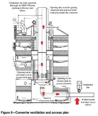
A ventilation and cooling scheme was prepared (see Figure 9). The plan was to hot-purge the converter to remove SO2 and SO3 from the catalyst and then cold-purge to cool the entire vessel. The lowest temperature that the converter could be cooled to was the blower outlet temperature (approx. 75°C). This temperature was too high for vessel entry so another means of cooling the converter core was required.
During a normal plant shutdown the converter manways would be opened and allowed to cool with ambient air. This procedure would have taken a long time, particularly for the central core of the converter where there would be little or no ventilation. The shutdown was scheduled for the wet season so there was a risk of introducing large amounts of moist air into the converter and exposing the catalyst to moisture.
To provide ventilation and cooling a 75 kW axial ventilation fan was installed to blow ambient air directly into the core to cool and ventilate the work area. The downstream ducts were isolated to prevent ambient air being blown through the catalyst beds (particularly bed 4). Inflatable duct balloons were used to provide isolation in the ducts in two locations (see Figure 10).
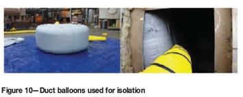
The duct balloons ensured that the cooling air was directed through the converter core and not through the catalyst bed. A temporary power line was routed to the fan from one of the absorber acid pumps power supplies so that the motor control centre (MCC) and variable frequency drive (VFD) of the pump could be utilized to power and control the fan. Having a VFD on the fan proved invaluable. During the initial cooldown the fan was run at full speed. However, once work commenced and the steel temperature had reduced, the fan was operated at a reduced speed to avoid excessive noise and air velocity in the working area.
Two entry points into the work area were provided. The first was at the top of the central duct at the inlet elbow. This would be the first entry point, allowing access to the bottom hot reheat exchanger tubesheet plate where a hole would be cut to provide the second entry point. Access was by a manbasket suspended from a crane. The top entry point was where materials and equipment would be lowered into the converter. A permanent platform was fabricated and installed to allow easy future access to the top of the converter. Once the opening in the bottom tubesheet plate was cut, the second entry point through the bypass duct was opened. This was the main access route for personnel working on the planned repairs.
Post-shutdown operation
After the modifications to the converter internals it was expected that control of bed 4 inlet temperature would improve. Although the bed 4 inlet temperature control improved, an unexpected consequence of the modification was the loss of bed 3 temperature control under certain operating conditions.
The design has a common bypass duct that splits to send cold gas to bed 3 and bed 4. At times, both bed 3 and bed 4 temperature control dampers open to 100%, indicating that the common duct is unable to provide sufficient cold bypass to control the inlet temperature of bed 3 and bed 4. The problem is currently under investigation to find a suitable solution.
Wet electrostatic precipitators
The wet electrostatic precipitators (WESPs) consist of four trains of primary and secondary units. The design flow through each train is 79 721 Nm3/h.
WESP performance/acid mist
The WESPs are equipped with sightglasses to monitor their performance. A sightglass is also provided in the main outlet duct to monitor the optical clarity of the gas going to the drying tower. During initial operation of the plant, observations through the duct sightglass showed poor acid mist collection when operating at low voltages and high gas flows. Voltages were increased to improve WESP performance, but issues were then experienced with the band heaters (see below).
A CCTV camera was installed at the sightglass so the quality of the gas could be monitored in the control room, allowing easier correlation of WESP performance and subsequently quality of the gas. When the problems with the band heaters were resolved, the maximum WESP operating voltage setting was raised to 60 kV. At this operating voltage an optically clear gas would be expected to be produced, but at high gas flow rates acid mist could still be observed through the duct sightglass.
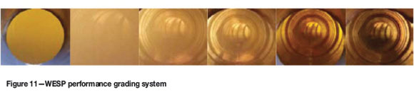
A qualitative grading system for gas quality was developed to assist in evaluating WESP performance. The scale ranged from Zero Visibility, Very Poor, Poor, Good, Very Good, to Optically Clear (see Figure 11). The gas quality was correlated with the gas flow through the WESP. In general, higher gas flows and lower operating voltages resulted in poorer WESP performance.
It was noted very early during the initial plant operation that the temperature of the gas entering WESP train no. 1 was higher than for the other three trains. The reason for this is that the air leaving the SO2 stripper is delivered into the WESP inlet header near the entrance to train 1. The higher operating temperature results in a slightly worse performance, which is apparent when the secondary voltage and current are compared with the readings for the other trains.
A trial was conducted that involved closing the air to the SO2 stripper and observing the performance of the WESPs in the sightglass. The temperature of the gas in train 1 decreased and its performance improved, as indicated by the secondary voltage and current. The mist that was visible in the sightglass cleared, but was still visible at high throughput.
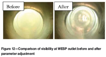
The WESP electrodes were realigned during the August 2016 shutdown, which created an opportunity for further adjustment of WESP operating parameters. To resolve the mist breakthrough issue the vendor, Outotec Sweden, sent a team to the site to review the parameters of both the primary and secondary WESPs. Adjustments were made to the WESP primary current limit (Ip), secondary current limit (Us), and the timing for increasing primary current by 1 A after flashover (slow ramp). The adjusted settings are shown in Table I.
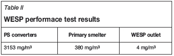
After the adjustments the flashovers per unit increased from 6 per minute to 16 per minute. The flashover rate is an important parameter for increasing the overall filter efficiency. These adjustments improved the WESP performance at high flow rates from 'very poor' to 'good' (see Figure 12). Mist quantification was conducted on the smelter scrubbers (PS converters and Isasmelt furnace) and the WESP outlets to ascertain how much mist was being captured (see results in Table II). The design mist exiting WESPs is 25 mg/Nm3.
Increasing the voltage and primary current settings on the WESPs increased the risk of burning the collecting tubes at low flow rates. In mid-February 2017 a significant deterioration in performance was noticed on three of the secondary WESPs, which proved to be due to burned collecting tubes. After the incident a separate parameter set for low flow and startup situations was set for the WESPs, with significantly reduced limits on the primary current and a lower maximum secondary voltage limit. The low flow parameter set is automatically activated by the DCS when the gas cleaning plant dry flow drops below 150 000 Nm3/h or if the WESPs are turned off. Normal operating parameters are automatically restored when the GCP dry flow is higher than 180 000 Nm3/h.
Band heaters
The WESPs are designed with totally enclosed insulator compartments which are kept hot with electric band heaters to prevent condensation on the ceramic insulators. The band heater temperature is measured and controlled by varying the power to the heaters. Initial operation of the WESPs was at relatively low voltage (approx. 35 kV).
As the WESP voltage was increased to achieve better collection efficiencies the WESP would trip due to a fault in the band heater temperature measurement circuit. The instrument input cards that received the band heater temperature signal from the field were failing. With theassistance of the vendor, it was determined that this was likely due to the temperature signal cables being run too close to the WESP main grounding cables. When a flashover occurred in the unit an electromagnetic pulse ran down the grounding cable, which then induced a current in the temperature signal cable. The resulting power spike in the signal cable caused the input card to fail.
Installing a steel shield between the cables did not resolve the issue. The existing signal cables were then replaced with fully shielded cables that were rerouted away from the grounding cables, and additional shielding installed around the earth cables, which resolved the issue. This allowed the WESP to be set for higher operating voltage levels without the units tripping.
WESP flushing
WESPs flushing is done to clean the collecting tubes of dust that has collected on the inside surface. Proper flushing of the WESPs was not possible due to a problem in the fabrication of the flushing piping and nozzles, which caused the spray nozzles to fall off. Also, the spray pattern of some of the nozzles was blocked by fogging water piping. The collecting tubes that were not adequately flushed experienced greater buildup of dust than those that were properly flushed.
The vendor supplied replacement spray nozzles and piping. Piping that blocked the sprays was relocated. Flushing of the WESPs is now much improved.
The WESP flushing pump was equipped with a constant speed electric motor. When a WESP is flushed, automatic valves open and close sending liquid to the flushing spray nozzles. The sudden opening and closing of these valves resulted in water hammer in the piping. The solution was to install a VFD. Flow is now increased and decreased at a slow rate, which avoids water hammer in the piping.
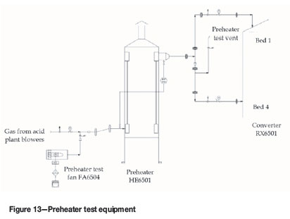
Preheater
Unplanned plant outages do occur due to equipment problems in the smelter and acid plant. Once all gas sources to the acid plant stop, the main blowers go on full recycle. If the outage is short, both blowers will be kept running. Even on full recycle there is still some gas that flows to the acid plant, which causes the converter beds to cool. If restart of the smelter is delayed, one blower is shut off, which reduces the rate of cooling of the converter. If the shutdown is further extended, all blowers are stopped and the converter isolated to conserve heat in the catalyst. The acid plant converter is able to restart without the use of the preheater after a 36hour stoppage.
During normal operation, the preheater is isolated with help of blanks at both preheater inlets to the first and fourth passes. Blanking is done to avoid cold sulphur dioxide gas ingress from the cold heat exchanger to the first pass, causing the converter to cool. When the preheater needs to be used due to a process upset or after a long shutdown, the blanks have to be removed before starting the preheater.
To bring the preheater online the delta P across the tubes has to be more than 1.5 kPa to avoid causing damage to the tubes. To achieve this, the main sulphur dioxide blower has to be running before the preheater is turned on. This creates a problem when a preheater has to be tested during normal plant operation, as this would necessitate removing the blanks and eventually cooling the bed during the test.
In order to resolve this problem an independent external 75 kW motor axial fan and air outlet port were installed on first pass inlet duct. The modification allows the operations team to test the preheater as and when required without disturbing the process.
Blower power consumption
During the plant performance test, data was collected to determine whether the blowers were operating at the expected design setting. The plant flow and pressure drop were close to the expected design settings, but the blower power consumption was significantly higher than expected. Possible causes such as power measurement errors were quickly eliminated. In the end, the most likely cause identified was leakage through the blower recycle damper.
The analysis of the blower operation used the suction and discharge pressure and the flow to the contact section. Gas flow measurement is done downstream of the blowers and the recycle duct. The arrangement is such that the blowers can be operating in partial recycle and the flow meter would not register the additional flow in the recycle because of its location downstream of the recycle duct. The blower power consumption would be higher than what the differential pressure across the blower and the flow would otherwise indicate.
To verify this theory, flow measurements were taken in the recycle duct with the recycle damper fully closed. A flow was measured in the duct, which confirmed the theory and explained the higher electrical power consumption that was measured.
The solution was to install a tight shutoff damper upstream of the existing control damper. In initial tests, the moment the tight shutoff damper was closed the blower current decreased and the inlet guide vanes closed more for the same operating conditions. The power savings over the life of the plant are significant.
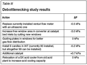
Acid plant debottlenecking study
Currently, the acid plant is designed to handle a maximum of 42 000 Nm3/h of SO2. After smelter ramp-up it became obvious that whenever sulphur in the concentrate feed was high, giving a sulphur factor above 160 Nm3/h of SO2 per ton concentrate smelted, the acid plant became a restriction for smelter production. During 2016, smelter production was restricted for a total of 98 days due to acid plant capacity. This restriction prompted us to request Outotec to perform a debottlenecking study for the acid plant in order to investigate possibilities for increasing the plant capacity. The results of the study are compiled in Table III. The modifications are expected to increase acid plant capacity by 3%, from 42 000 Nm3 of SO2 per hour to 43 260 Nm3/h. The modifications will be implemented in the upcoming Isa furnace rebricking shutdown in August 2017.
Acknowledgement
We would like to thank Kansanshi Mining PLC for permission to present this paper.
References
Mumba, B., deVries, D., and Mohsler, S. 2015. Zambia's newest copper smelter and sulphuric acid plant. Sulphur 2015, Proceedings of the 31st Annual Conference of Sulphur and Sulphuric Acid,, Toronto, Canada, 9-12 November. CRU Group. [ Links ]
Mumba, B. and Louie, D. 2016. Two years of operation for Kansanshi's sulphuric acid plant. Proceedings of the Sulphur 2016 International Conference and Exhibition, London, UK., 7-10 November. CRU Group. [ Links ] ♦

