


Servicios Personalizados
Articulo
 Inglés (pdf)
 Articulo en XML
 Referencias del artículo
Indicadores

Links relacionados
-
 Citado por Google
 -
 Similares en Google
Compartir

 Permalink
Journal of the Southern African Institute of Mining and Metallurgy
versión On-line ISSN 2411-9717
versión impresa ISSN 2225-6253
J. S. Afr. Inst. Min. Metall. vol.117 no.10 Johannesburg oct. 2017
http://dx.doi.org/10.17159/2411-9717/2017/v117n10a2
CONFERENCE PAPERS
Design and fabrication of a chemical vapour deposition system with special reference to ZrC layer growth characteristics
S. BiiraI, II; P.L. CrouseI; H. BissettIII; T.T. HlatshwayoI; J.H. van LaarI; J.B. MalherbeI
IUniversity of Pretoria, South Africa
IIBusitema University,Uganda
IIIThe South African Nuclear Energy Corporation (Necsa), Pretoria, South Africa
SYNOPSIS
The overall aim of this research project was to design and construct an in-house, thermal chemical vapour deposition (CVD) reactor system, operating at atmospheric pressure. Radio frequency (RF) induction heating was used as the energy source, with a vertical-flow design, using thermally stable materials. The steps in the design and construction of this CVD system are described in detail. The growth conditions at different substrate temperatures, gas flow ratios and substrate-gas inlet gaps were assessed as part of the project. The growth rate of ZrC layers increases with increasing substrate temperature. The microstructure properties of the ZrC layers such as lattice parameters and orientation of crystal planes were all found to be dependent on deposition temperature. The increase in free carbon in the as-deposited coatings as the temperature increased was found to be a stumbling block for obtaining stoichiometric ZrC coatings. The surface morphology of the as-deposited ZrC layers also depends on the deposition parameters.
Keywords: ZrC, chemical vapour deposition, RF heating.
Introduction
Chemical vapour deposition (CVD) systems are used in applications that require the deposition of layers or coatings of a material onto a surface (Park and Sudarshan, 2001). CVD plays an important role in the fabrication of microelectronic devices and in the formation of protective coatings (Pierson, 1999). CVD processes have been widely used commercially; however, the detailed design and optimisation of inexpensive CVD equipment and processes are not well described. Therefore the objectives of this study were; (1) to design and fabricate a CVD system, (2) to establish the operating conditions for achieving deposition in CVD mode and (3) then to deposit ZrC layers from ZrCl4 and methane.
Zirconium carbide (ZrC) is very hard interstitial refractory carbide (Pierson, 1996) which has been proposed as a possible new material to be used as a protective coating layer for nuclear fuel particles because of its excellent properties (Meyer Fielding and Gan, 2007; Katoh et al., 2013). For example, ZrC has a very high melting temperature of about 3540°C and low density of 6.59 g/cm3 compared to other refractory carbides. It is chemically inert to various reagents and highly resistant to corrosion and wear (Pierson, 1996; Won et al., 2007). Many attempts have been made to grow ZrC layers; however, growing polycrystalline ZrC layers with good stoichiometry has remained a challenge. CVD has been identified as a suitable technique for the deposition of layers with relatively high purity and uniformity levels (Yan and Xu, 2010).
Equipment fabrication, construction and ZrC deposition
Prior to the designing of the CVD system for the deposition of ZrC layers shown in Figure 1, a thermodynamic analysis was carried out. This was done in order to establish the feasibility of the chemical reactions both at room conditions and at elevated temperatures. The thermodynamic analysis results were used as guidelines for the selection of the appropriate materials for the reactor system. The zirconium and carbon sources source materials were ZrCl4 and CH4 respectively. The feasibility of the chemical reaction relies on the change in Gibbs free energy. When the Gibbs free energy of the reaction is negative, then the reaction is feasible at the given conditions (Yan and Xu, 2010). The Gibbs free energy of formation and the corresponding equilibrium thermodynamic constant were calculated. The results are given in a previous publication (Biira et al., 2017b). HSC Chemistry software (a thermochemical software package) was also used to show the speciation of the reactants with temperature (Biira et al., 2017b). Based on the results of the thermodynamic analysis, deposition temperatures ranging from 1200°C to 1600°C were selected.
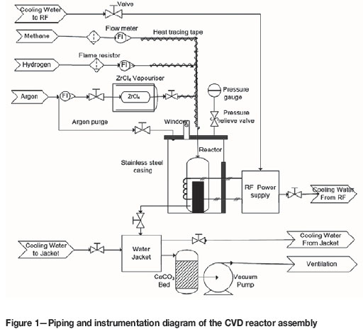
In this study a vertical-wall thermal CVD system, as indicated in Figure 1, was developed in-house at the South African Nuclear Energy Corporation (Necsa) SOC Ltd. This in-house-built CVD system consisted of four basic components. These were (i) the gas supply and delivery system (including ZrCl4 vaporiser system), (ii) an RF power supply system and induction coil, (iii) the reactor system (including the graphite reaction chamber) and (iv) exhaust/scrubber system.
Power supply system and calibration
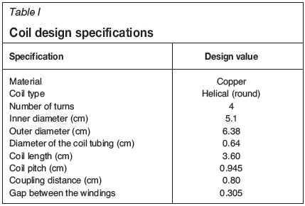
An RF induction heating source with maximum power output of 10 kW was used. This RF power supply model EASYHEAT LV AT 8310 was manufactured by Ambrell, Ameritherm Inc., USA. It was connected to a copper tubing induction heating coil. The coil was made of copper in order to minimise the heat losses and to maximise heating efficiency. The copper coil was water-cooled to prevent melting. The gap between the four-turn helical copper coils and the graphite reaction chamber was kept to a minimum to ensure good RF coupling. This distance was sufficient to accommodate the thermal insulation (using ceramic material) to reduce heat transfer from the heated graphite reaction chamber to the coil. The ceramic material also secured the graphite reaction chamber at the centre of the coil in a fixed position. When the material to be heated is placed close to the coil, the current increases, thus increasing the amount of heat induced in material. To achieve uniform heating the coupling distance Cd should be equal to, but not more than, twice the coil pitch (Simpson 1960), since heating effects also depends on the pitch of coil windings. The coupling distance was estimated using Equation ([1]):
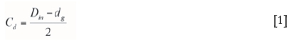
where Dinis the inner diameter of the coil and dg is the diameter of the graphite reaction chamber (acting as the workpiece). Table I gives the summary of the specifications of the coil used. To ensure maximum uniform heating, the effective heating length of the coil on the graphite reaction chamber was estimated using Equation [2] (Wai, Aung and Win, 2008) and was found to be 6.34 cm.
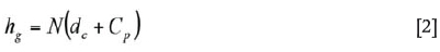
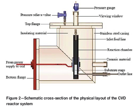
where hgis the portion of the length of the cylindrical graphite tube with maximum heating, Cpis the pitch of the coil winding, dc is the diameter of conductor (copper tubing) and N is number of coil turns able to produce maximum uniform heating on about 6.34 cm of the length of the graphite reaction chamber. The substrate temperatures were measured by an infrared optical pyrometer through a quartz viewing window at the top of the flange (see Figure 2). The power calibration experiments were carried out five times and the average temperature values were considered to avoid errors that may arise from the pyrometer readings.
CVD reactor system
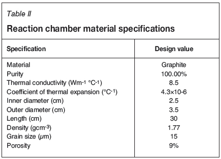
The CVD reactor system shown in Figure 1 was fabricated and constructed at Necsa. The elbow stainless steel outer casing and the graphite reaction chamber are among the many components. The schematic of the CVD reaction chamber system and components is given in Figure 2. One of the roles of the stainless steel outer casing was to confine the corrosive exit gases and enable safe extraction. The cylindrical high-density graphite tube manufactured by Le Carbone-Lorraine had an inner diameter of 2.5 cm and a length of 30 cm. The cylindrical graphite tube (reaction chamber), together with a substrate stage made of the same material attached at its bottom end, was fixed inside the steel casing (see Figure 2). The 74.1 g solid cylindrical graphite substrate stage had a length of 13.5 cm and diameter of 2.2 cm. This graphite tube was at the same time used as the workpiece for induction heating to attain the required temperature for the substrates (1200°C up to 1600°C for this experiment). Table II gives the summary of the material specifications and properties of the graphite tube that was used in this study. The graphite tube was equipped with leads on both ends, i.e. the gas inlet at the top and outlet at the bottom. The gas inlet and outlet permitted the flow of the gases past the heated substrates mounted on substrate stage. The distance from the inlet to the substrate stage varied between 70 mm and 170 mm. Zirconia wool was used for both thermal and electrical insulation and was placed between the steel casing and the graphite reaction chamber.
Gas delivery system
The gas delivery system comprised three separate gas cylinders (methane, argon and hydrogen cylinders) fitted with pressure gauges and flow meters. The precursors used in deposition of ZrC were anhydrous zirconium tetrachloride powder (purity > 99.5%; Hf < 50 mg kg-1 manufactured by Sigma-Aldrich (Pty) Ltd) and methane (CH4, 99.99% pure). ZrCl4 was carried from the vaporisation chamber to the reaction chamber by argon (Ar, 99.999% pure). Hydrogen gas (H2, 99.999% pure) was used to provide a reducing and diluting environment for the ZrCl4 vapour and the HCl effluent. Argon was also used to flush the reactor by continuously (four times before each deposition) pressurising and depressurising it in order to remove air (oxygen) and atmospheric moisture. Methane, hydrogen and argon flow rates were measured by calibrated rotameters and directed into the reaction chamber as shown in Figure 1 and Figure 3. The deposition was carried out at atmospheric pressure (which was about 87 kPa absolute at the location).
The volumetric flow rates of argon, hydrogen and methane were controlled manually by pre-calibrated flow meters. Argon was passed through the vaporiser loaded with ZrCl4 powder so that it can carry the ZrCl4 vapour to the reaction chamber at the required flow and proportion. The stainless steel feed pipes carrying hydrogen, methane and ZrCl4 (under argon) were joined together and then fed in the reaction chamber. To avoid ZrCl4 agglomerating and clogging the inlet pipe, the feed pipes were heated to 300°C (ZrCl4 vaporiser temperature) by an electric heat tracing tape. Argon was also used as a purge gas and to stabilise the total reactor pressure.
ZrCU vaporisation system
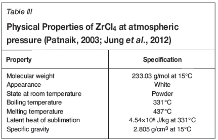
The control and transport of ZrCl4 vapour into the reaction chamber are crucial for the production of ZrC with the desired stoichiometry and morphology. ZrCl4 was first vaporised in the vaporisation system and the vapour was continuously swept to the reaction chamber using argon carrier gas. ZrCl4 was vaporised to the required vapour pressure in order to optimise the growth characteristics of the ZrC layers. The ZrCl4 vaporisation system consisted of an oven heated to 300°C (just below the phase transition temperature of 331°C) and a cylindrical steel vessel 24.6 cm long with inner diameter of 4.3 cm. The loaded cylindrical steel pot was connected to the inlet pipes and argon was allowed to sweep through freely. Several studies have been conducted on the CVD growth of ZrC from zirconium halides. It has been noted that ZrCl4, as opposed to other halides such as ZrBr4 and ZrI4, produces ZrC with relative good stoichiometry and is less toxic and relatively more volatile (Park et al., 2008). That is the reason it was selected as precursor. The physical properties of ZrCl4 are listed in Table III.
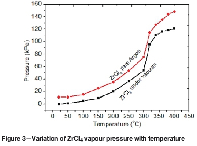
Since ZrCl4 powder is very hygroscopic, precautions were taken to avoid its exposure to atmospheric moisture as far as possible. To determine and optimise the vapour pressure of ZrCl4 for the deposition of ZrC layers, ZrCl4 was heated under vacuum and under argon for 3 minutes for each temperature. Figure 3 shows a plot of the gauge pressure as a function of temperature, measured under vacuum and at argon gauge pressure of 11 kPa. For ZrCl4 under argon, the total pressure measured was the sum of the ZrCl4 (vapour) and argon partial pressures. It was observed that the presence of argon in the ZrCl4 does not change the pressure-temperature trend of ZrCl4 as shown in Figure 3. From room temperature up to 150°C the increase in pressure of ZrCl4 is small and then there is a rapid increase from around 190°C to about 330°C. A quick rise in vapour pressure was due to an increase in ZrCl4 vapour molecules as the temperature is increased (Liu et al., 2008). After 330°C the trend of the curve changed, indicating full sublimation of the ZrCl4. To avoid full sublimation and keep the vapour pressure at a manageable level, a temperature of 300°C was chosen throughout this study.
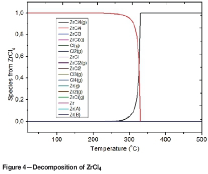
We also investigated, by thermodynamic analysis, the ZrCl4 vaporisation process. It was found that the vaporisation of ZrCl4 does not generate other halide phases or form other lower halides such as ZrCl3, ZrCl2or ZrCl as illustrated in Figure 4. This is because the Gibbs free energies of formation of ZrCl3, ZrCl2 and ZrCl are all greater than zero.
ZrCl4 mass transfer rate calibration
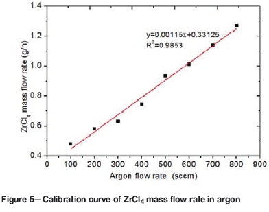
As mentioned, the ZrCl4 vapour was delivered into the reaction chamber by an argon flow, subsequently mixed with the methane and the hydrogen feed. The vapour pressure and the mass transfer rate of ZrCl4 depend mainly on the temperature at which ZrCl4 is vaporised and the argon flow rate. The mass flow rate of ZrCl4 was controlled by varying the argon flow rate and keeping the temperature at 300°C.
The ZrCl4 mass transfer rate as a function of argon flow rate is shown in Figure 5. The calibration curve was obtained by flowing argon through the ZrCl4 powder at different argon flow rates each for 20 minutes and determining the mass difference every after each run. The mass transfer rate ZrCl4 for each run was determined from Equation [3], derived experimentally:
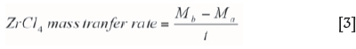
where Mb is the mass of the loaded ZrCl4 vaporiser before vaporisation and argon flow and Ma is the mass of the loaded ZrCl4 vaporiser after vaporisation and argon flow for time t.
Exhaust system
The exhaust system was another essential part of the system. It consisted of a vacuum pump, cooling water jacket, scrubber containing calcium carbonate chips (CaCO3) and extraction ventilation. The hot exit gases from the reaction chamber were first passed through a coiled steel pipe equipped with a cooling water jacket before entering the scrubber containing calcium carbonate. The reason for passing the exit gases through the calcium carbonate scrubber was to remove hydrogen chloride gas and any unreacted ZrCl4 before it was released through the extraction system. Within the scrubber, a dust trap was installed to filter the exhaust gases before release into the environment. To regulate the reactor total pressure and to avoid accumulation of the exit gases in the reactor, which may otherwise cause contamination of the deposit, the reactor system was connected to a rotary vane vacuum pump.
Hydrogen and methane are explosive and flammable gases, whose flammabilities are enhanced by high temperature, pressure and the presence of oxygen. Since the experimental environment was characterised by these conditions, caution was employed to reduce the associated dangers. The maximum flow rates of hydrogen and methane commensurate with safety and environmental considerations were determined. This was based on the minimum concentrations of hydrogen and methane necessary to support combustion, referred to as lower flammable or explosive limit (LFL or LEL). The standard LFLs of hydrogen and methane at room temperatures are 4% and 5% by volume respectively. The maximum hydrogen or methane flow rates that were used for these experiments were 42 cnWmin (approx. 0.7 cm3/s) and 870 cm3/min. These values were assumed to be the maximum leakage rates. Therefore, the percentage hydrogen or methane concentrations in the extraction were found to be 0.070% and 0.0034%, which were below the LFLs of 4% and 5% for hydrogen and methane respectively. Therefore the Necsa restriction of the hydrogen and methane concentrations being below 20% of its LFL was also satisfied.
Before and during each experiment the gas leakages along the gas supply lines, the reactor system and the exhaust lines were monitored. This was done by (1) pressurising the reactor with argon and leaving it for over two hours and monitoring the pressure drop, (2) checking the joints with soap bubbles and (3) using a hydrogen leak detector. When the required minimum leakage rate was achieved, the CVD system was considered fit for deposition. In fact whenever there was a leak, the ZrC layer hardly grew on the substrate and when any deposition did occur the layer uniformity was compromised.
Substrate preparation
The substrates of average diameter 10 mm and thickness 2.5 mm were cut from the bulk high-density (1.71g cm-3) graphite discs. These substrates had the same physical properties as those of the graphite reaction chamber listed in Table II. These graphite substrates were hand polished on a polishing wheel using 1000 grit silicon carbide paper. They were then sequentially cleaned by ultrasonic agitation with acetone, ethanol and then demineralised water for 20 minutes each. The cleaning and polishing was done in order to remove any oils, oxides and other contaminants so as to enhance adhesion and reduce the number of impurities in the layer being deposited. The clean substrates were dried in an oven at 200°C for 2 hours and then weighed to determine the mass of each substrate before deposition. The substrates were then kept in airtight desiccators ready for deposition. Prior to deposition, the substrates were mounted on the clean graphite substrate stage inside the graphite reaction chamber. The substrate stage was cleaned in a similar way as the substrates themselves to avoid contamination. The substrate stage was positioned such that its top, where the substrates sit, was within the area circumscribed by the induction coil. This was done to maximise and control the temperature.
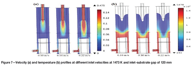
Effect of substrate-inlet gap and gas velocities on the gas flow dynamics in the reactor
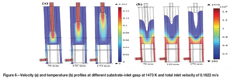
In an effort to understand and explain the complex gas flow mechanisms and layer growth characteristics, the finite element analysis software, COMSOL Multiphysics® 5.1 was used to study the temperature and velocity profiles in the reactor. The effects of substrate-in let gap and gas flow velocities on the flow dynamics were simulated (Figure 6 and Figure 7). This numerical model analysis incorporates the conservation equations of momentum, energy and species. The model simulation results revealed that approximately uniform temperature and velocity profiles existed in the reactor, the magnitudes of which depend on the substrate-inlet gap and gas velocity. The results of this simulation are important for the optimisation of the CVD operating conditions to achieve a high and uniform ZrC growth in the vertical reactor. This was verified by calculating the boundary layer thickness.
The boundary layer thickness was calculated from Equation [4] (Pierson, 1999):
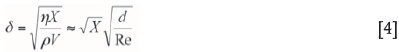
Here n is the viscosity of the reactants, p is the density, V is the velocity of reactants, Re is the Reynolds number and d is the diameter of the reaction chamber. The detailed calculations of these variables plotted in Figure 8a and 8b are given in Biira et al. (2017a).
Keeping other factors constant it was found that increasing the substrate-gas inlet gap increased the boundary layer thickness and increasing the gas flow velocity reduces the boundary layer thickness. The higher the boundary layer thickness the thinner the layer thickness because fewer reactants reach the substrate. This in turn also affects the quality and uniformity of the growing surfaces.
Effect of deposition temperatures on the growth characteristics of ZRC layers
Deposition rate ofzirconium carbide
The average growth rate of the ZrC layers was calculated from the mass gain, the surface area of the substrate and theoretical density of ZrC (6.59 g/cm3) (Biira et al., 2017b). The deposition rate of the ZrC layers increased with increase in substrate temperature as shown in Figure 9a. There was a sharp increase in growth rate between 1200°C and 1300°C and a more gradual increase thereafter. This is because increasing temperature increases both the rate of decomposition of the reacting species and their reaction kinetics at the substrate surface. The linear fit of the Arrhenius plot in Figure 9b gives an apparent activation energy of 38.66 kJ/mol. However, it looks as if there might be a two-regime growth mechanism; one between 1200°C and 1300°C with an apparent activation energy value of 97.87 kJ/mol and the other between 1300°C and 1600°C with an apparent activation energy value of 19.28 kJ/mol. The apparent activation energy of the ZrC CVD reaction was determined from the Arrhenius Law, as given in Equation [5] (Park and Sudarshan, 2001):
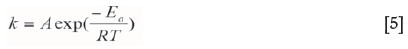
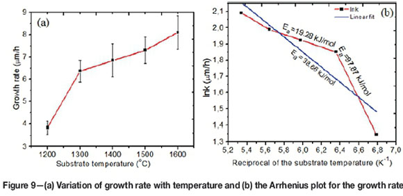
where Eais the apparent activation energy, T is the deposition temperature; R is the gas constant and A is the constant. The growth rate, k, was calculated as described in Biira et al., 2017b). Apparent activation energy, which is a function of reactant concentration and temperature, can be used to determine the rate limiting growth mechanism (Kashani, Sohi and Kaypour, 2000; Wagner, Mitterer and Penoy, 2008). Therefore the two regimes on the Arrhenius plot might be a representation of surface reactions as the limiting mechanism between 1200°C and 1300°C, since apparent activation energy is high, nd mass transport mechanism for the substrate temperatures between 1300°C and 1600°C for the low apparent activation energy of 19.28 kJ/mol.
Crystallographic structure and phase composition
The structure of the as-deposited ZrC layers was analysed using a Bruker XRD D8 Advance with a Cu Karadiation source ( λ=1.5406 Å). The working potential and current were set at 40 kV and 40 mA respectively. Figure 10 shows the XRD patterns of ZrC layers for substrate temperature ranging from 1200°C to 1600°C. At 1200°C only ten reflections of the ZrC phase were observed, viz. (111), (200), (220), (311), (222), (400), (331), (420), (422) and (511). These plane reflections indicated that the polycrystalline face-centred cubic structure of the ZrC layer was deposited, when matched with International Centre for Diffraction Data (ICDD) file number 03-065-8833. As the temperature was increased from 1300°C to 1600°C some carbon peaks started to emerge, the intensities of which became increasingly prominent as the substrate temperature increased.
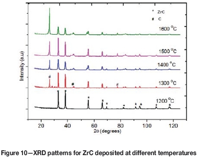
The presence of free carbon in ZrC with increase deposition temperatures was also reported by Wang et al. ( 2008). The increase in carbon content may be attributed to the differences in the decomposition rates of methane and ZrCl4 as the temperature in the reaction zone is increased. This means that there is more atomic carbon than Zr and the excess carbon is deposited as free carbon with increasing temperature.
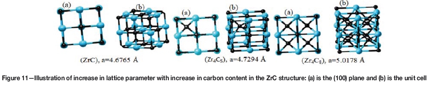
The lattice parameters of the ZrC layers at different temperatures were determined from the Miller indices (hkl) and interplanar spacing of the various planes (Cullity and Stock, 1956; Nelson and Riley, 1945). The lattice parameter was found to increase from 4.6763 À to 4.7011 Á. The change in the lattice constant values of the as-prepared ZrC layers may be due to strain in the layers. The strain in the ZrC layers may partly originate from the presence carbon impurities in the lattice, the amount of which increased as the substrate temperature was increased, as shown in Figure 10. To confirm this, we added excess carbon onto the stoichio-metric ZrC structure to evaluate some possible structures. This was done by the help of an electron structure software program for solids, surfaces and interfaces; the Vienna Ab initio Simulation Package (VASP) V4.6. It was observed that the average lattice parameter value increased as excess carbon is added, as illustrated in Figure 11. The presence of carbon impurities decreases the number of neighbour atoms of the Zr-C structure. This gives rise to relaxation of the lattice, causing the lattice parameter to increase.
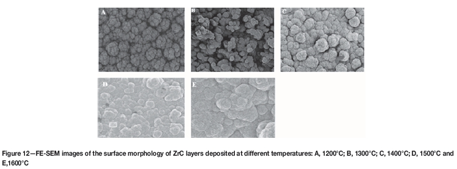
Surface morphology
The surface morphology of the as-deposited ZrC layers was characterised by field emission scanning electron microscopy (FE-SEM) using a Zeiss Ultra Plus instrument at an acceleration voltage of 1 kV. Figure 12 shows the surface morphology of ZrC coatings obtained at 1200°C to 1600°C. At 1200°C the coating ball-shaped grains cling together forming cauliflower-like grains surrounded by abundant pores. This indicates that small grains agglomerate to form much larger grains. The ball-shaped grains become much dense and broader as the temperature is increased from 1300°C to 1600°C. No obvious cracks were observed at all substrate temperatures. The reduction of the numerous pores as the temperature is increased may be due to the fact that increasing temperature increases the energy of the reacting species, which may enhance surface diffusion at the substrate surface. As the temperature is increased, more of the reacting species are decomposed and therefore readily combine to form the layer. This increases the size of the growing crystals. It be can be concluded that the substrate temperature controls the morphology of ZrC coatings and the uniformity of the coating growth (Li et al., 2009).
Conclusion
An inexpensive thermal CVD system was successfully designed and fabricated in-house for depositing a variety of films and coatings for various research and industrial applications. System parameters were optimised so as to achieve the required coating. These parameters included temperature, substrate-inlet gap and gas flow velocity. To confirm the capability of the CVD system, ZrC layers were successfully deposited on graphite substrates at atmospheric pressure for 2 hours at different temperatures. The results indicate that the substrate temperature has a determining influence on growth kinetics, surface morphology and microstructure of ZrC layers. Generally, increasing the substrate temperature increases the deposition rate of ZrC layers. Surface reaction is the controlling mechanism between 1200°C and 1300°C, whereas mass transport controls the deposition process between 1300°C and 1600°C. The results also show that the lattice parameter and the carbon content in the ZrC layers increase with substrate temperature. SEM micrographs show that increasing temperature increases the size of the particles, with the layer surface becoming more uniform with no noticeable cavities.
Acknowledgements
Necsa and the Department of Science and Technology of South Africa through the Nuclear Materials Development Network of the Advanced Metals Initiative are gratefully thanked for the provision of experimental materials and laboratory space. S. Biira acknowledges the financial support from the University of Pretoria and Busitema University.
References
Biira, S., Alawad, B.A.B., Hlatshwayo, T. T., Crouse, P.L., Malherbe, J.B., Bissett, H., Ntsoane, T.P. and Nel, J.T. 2017a. Influence of the substrate gas-inlet gap on the growth rate, morphology and microstructure of zirconium carbide films grown by chemical vapour deposition. Ceramics International, vol. 43, no. 1. pp. 1354-1361. [ Links ]
Biira, S., Crouse, P.L., Bisset, H., Alawad, B.A.B., Hlatshwayo, T.T., Nel, J.T. and Malherbe, J.B. 2017b. Optimisation of the synthesis of ZrC coatings in an RF induction-heating CVD system using surface response methodology. Thin Solid Films, vol. 624. pp. 61-69. [ Links ]
Cullity, B.D. and Stock, S.R. 1956. Elements of X-ray Diffraction. 1st edn. Cohen, M. (ed.). Addison-Wesley, Massachusetts. [ Links ]
Jung, Y.M., Gyeong, M.K. and Moonyong, L. 2012. Measurement of bubble point pressures of zirconium and hafnium tetrachloride mixture for zirconium tetrachloride purification process. International Journal of Chemical Engineering and Applications, vol. 3, no. 6. pp. 427-429. [ Links ]
Kashani, H., Sohi, M.H. and Kaypour, H., 2000. Microstructural and physical properties of titanium nitride coatings produced by CVD process. Materials Science and Engineering A, vol. 286, no. 2. pp. 324-330. [ Links ]
Katoh, Y., Vasudevamurthy, G., Takashi, N. and Snead, L.L. 2013. Properties of zirconium carbide for nuclear fuel applications. Journal of Nuclear Materials, vol. 441, nos.1-3. pp. 718-742. [ Links ]
Li, H., Zhang, L., Cheng, L. and Wang, Y. 2009. Oxidation analysis of 2D C/ZrC- SiC composites with different coating structures in CH4 combustion gas environment. Ceramics International, vol. 35. pp. 2277-2282. [ Links ]
Liu, C., Liu, B., Shao, Y.L., Li, Z.Q. and Tang, C.H. 2008. Vapor pressure and thermochemical properties of ZrCl4 for ZrC coating of coated fuel particles. Transactions of Nonferrous Metals Society of China (English Edition), vol. 18 (863614202), pp. 728-732. [ Links ]
Meyer, M.K., Fielding, R. and Gan, J. 2007. Fuel development for gas-cooled fast reactors. Journal of Nuclear Materials, vol. 371, no. 1. pp. 281-287. [ Links ]
Nelson, J.B. and Riley, D.P. 1945. An experimental investigation of extrapolation methods in the derivation of accurate unit-cell dimensions of crystals. Proceedings of the Physical Society, vol. 57, no. 3. pp. 160-177. [ Links ]
Park, J. and Sudarshan, T.S. 2001. Chemical Vapor Deposition. ASM international, Chicago. [ Links ]
Park, J.H., Jung, C.H., Kim, D.J. and Park, J.Y. 2008. Temperature dependency of the LPCVD growth of ZrC with the ZrCl4-CH4-H2 system. Surface and Coatings Technology, vol. 203, nos. 3-4. pp. 324-328. [ Links ]
Patnaik, P. 2003. Handbook of Inorganic Chemicals. McGraw-Hill, New York. [ Links ]
Pierson, H.0.1999. Handbook of Chemical Vapor Deposition: Principles, Technology and Applications. 2nd edn. William Andrew, New York. [ Links ]
Pierson, H.0.1996) Handbook of Refractory Carbides and Nitrides: Properties, Characteristics, Processing and Applications. Noyes Publications, New Jersey. [ Links ]
Simpson, P.G. 1960. Induction heating: coil and system design. McGraw-Hill, New York. [ Links ]
Wagner, J., Mitterer, C. and Penoy, M. 2008. The effect of deposition temperature on microstructure and properties of thermal CVD TiN coatings. International Journal of Refractory Metals and Hard Materials, vol. 26, no. 2. pp. 120-126. [ Links ]
Wai, H.P., Aung Jr, S.S. and Win, T. 2008. Work coil design used in induction hardening machine. Work Academy of Science, Engineering and Technology, vol. 44. pp. 352-356. [ Links ]
Wang, Y., Liu, Q., Liu, J., Zhang, L. and Cheng, L. 2008. Deposition mechanism for chemical vapor deposition of zirconium carbide coatings. Journal of the American Ceramic Society, vol. 91 (23650). pp. 1249-1252. [ Links ]
Won, Y.S., Varanasi, V.G., Kryliouk, 0. Anderson, T.J., McElwee-White, L. and Perez, R.J. 2007. Equilibrium analysis of zirconium carbide CVD growth. Journal of Crystal Growth, vol. 307, no. 2. pp. 302-308. [ Links ]
Yan, X.T. and Xu, Y. 2010. Chemical Vapour Deposition: an Integrated Engineering Designfor Advanced Materials. 1st edn. Springer-Verlag, London. [ Links ] ♦
This paper was first presented at the AMI Precious Metals 2017 Conference 'The Precious Metals Development Network' 17-20 October 2017, Protea Hotel Ranch Resort, Polokwane, South Africa.

