


Servicios Personalizados
Articulo
 Inglés (pdf)
 Articulo en XML
 Referencias del artículo
Indicadores

Links relacionados
-
 Citado por Google
 -
 Similares en Google
Compartir

 Permalink
Journal of the Southern African Institute of Mining and Metallurgy
versión On-line ISSN 2411-9717
versión impresa ISSN 2225-6253
J. S. Afr. Inst. Min. Metall. vol.117 no.6 Johannesburg jun. 2017
http://dx.doi.org/10.17159/2411-9717/2017/v117n6a3
PAPERS OF GENERAL INTEREST
Strapping of pillars with cables to enhance pillar stability
L.R. AlejanoI, *; J. ArzúaII; U. Castro-FilgueiraI; F. MalanIII
IDepartment of Natural Resources & Environmental Engineering, University of Vigo, Spain
IIDepartment of Metallurgical and Mining Engineering, Universidad Católica del Norte, Antofagasta, Chile
IIIDepartment of Mining Engineering, University of Pretoria, Pretoria, South Africa
SYNOPSIS
Pillar design for underground mining is typically done using empirical formulae or numerical modelling. Practical experience and recent literature, nevertheless, illustrate the shortcomings of these design approaches. Ongoing monitoring of pillars is therefore recommended to minimize the risk associated with these designs.
In a mine where a large number of pillars are cut, different pillar strengths can be expected owing to variations in rock mass strength from area to area. This problem is compounded by the fact that in mining environments the pillars are not always cut according to the prescribed dimensions. Although the original design using either empirical methods or modelling may predict stable pillars, unstable pillars will be encountered in reality. Very conservative designs with large factors of safety may circumvent this problem, but this approach is uneconomical.
A possible solution to localized stability problems may be to enhance the strength of a few unstable pillars. It may even be hypothesized that reinforcing a few critical pillars may prevent 'pillar runs' on a much larger scale. Rockbolting, strapping of pillars, and pillar shotcreting have occasionally been used in the past as possible solutions. It appears that these have not been successful in all cases and large collapses have occurred in spite of the pillar remedial work.
The authors investigated the strapping of pillars by conducting laboratory tests on cabled rock specimens. The results were qualitatively compared to actual attempts of pillar reinforcement available in the literature, as well as additional observations in an old haematite room-and- pillar mine in Spain. Based on these results, the value of steel cabling and mesh wrapped around pillars to improve stability is demonstrated. Some cases where this approach will not be successful are also discussed.
Keywords: room and pillar mining, pillar stability, support, strapping, cables.
Introduction
Although the extraction ratios in room and pillar mining can be low in some cases, it is still a widely used mining method for coal, base metals, industrial minerals (quartz, magnesite, rock salt), and ornamental stone (marble, slate). A major reason is that it tends to be cheaper than fill methods and is more environmentally friendly compared to caving methods (Alejano et al., 2012).
Classic empirical pillar strength formulae are typically used as a first approximation for the design of pillars in coal (Salamon and Munro, 1967; Hustrulid, 1976; Bieniawski, 1992), hard rock (Hedley and Grant, 1972), and metal mines (Lunder and Pakalnis, 1997). This, in combination with stress estimates
Recent reviews of pillar design methods and studies on typical problems encountered in room and pillar mines have nevertheless indicated that neither classic empirical formulae nor numerical methods will always guarantee stable designs (Malan and Napier, 2011; Hedley, Roxburgh, and Muppalaneni, 1984; Dismuke, Forsyth, and Stewart, 1994; van der Merwe, 2006). The variable strength of the rock mass may lead to local instabilities, or massive collapses may even be encountered (Malan and Napier, 2011). Very conservative designs, on the other hand, are also not satisfactory as they result in poor mineral extraction.
An evaluation of the strength of slender pillars based on a number of pillar failures in mines was conducted by Esterhuizen (2006). This indicated that for pillars having a width to height ratio in the range of 0.6 to 0.7, failure has been observed for pillar stresses varying between 20% and 65% of the laboratory rock strength. This is a wide range and illustrates that care should be exercised when choosing conservative designs to ensure safety versus higher extraction ratios to ensure more profitable operations.
Khair and Peng (1985), Chase, Zipf, and Mark (1994), and Zipf (2001) describe collapses of room and pillar mines in the USA. Malan and Napier (2011), van der Merwe (2006), and Madden, Canbulat, and York (1998) reviewed a number of similar collapses in South Africa. Similar studies have been conducted in Brazil, China, and Kazakhstan (Zingano, Koppe, and Costa, 2004; Wang, Shang, and Ma, 2008; Mansurov and German, 2009). The term 'catastrophic pillar failure' describes the mechanism whereby one or a few pillars fail initially; their load is then transferred to adjacent pillars, which also fail. This may result in a 'pillar run' and hundreds of pillars may fail in the process. It is hypothesized that if the initial pillars remain stable, catastrophic pillar failure can be prevented.
Based on this information and hypothesis, it would be useful for the mining industry to have an inexpensive technique available that can be easily applied to stabilize pillars after the initial signs of failure are observed. Such a technique, based on a laboratory study and tested in one mine, is presented in this paper. After the unstable pillars have been identified, the proposal is to wrap mesh around these pillars and then attach a number of pre-stressed steel cables around the pillar. This technique can also be applied to pillars that initially appear stable but are subjected to smaller factors of safety caused by poor blasting or poor excavation control.
The application and studies of similar techniques have very seldom been reported in the literature. In South Africa, a few cases exist of hard rock pillar failure where attempts were made to strengthen the pillars. Malan and Napier (2011) describe the reinforcement of pillars traversed by thick clay layers (up to 300 mm thick in some cases) using mesh and lacing (cabling) at the Wonderkop mine. The reinforcement of the pillars in this case was unfortunately not successful and the mine collapsed. This failure was attributed to the drilling process, which introduced additional water into the clay and this probably weakened the pillars further. The same authors reported a further failed attempt to increase the pillar confinement using fibre-reinforced shotcrete in a platinum mine in the Bushveld Complex. Siwak (1984) reported a similar failure in pillars in underground chalk quarries in northern France. The pillars were supported with a 6 mm thick layer of glass fibre reinforced resin, but the additional confinement only delayed, and did not prevent, the eventual failure. In contrast, Esterhuizen et al. (2011) reported the apparently successful use of rib pillar support, such as chain link mesh and bolts, to prevent further deterioration of large pillars in underground stone mines in the USA.
Collapses have occurred in Lorraine (France) during the last 50 years above abandoned room- and- pillar iron ore mines (Grgic, Hommand, and Hoxha, 2003). Wojtkoviak, Rai, and Bonvallet (1985) presented an interesting study of the effectiveness of various approaches to pillar reinforcement based on laboratory test samples. These included mine fill, rockbolting, shotcrete or resin spraying, and steel banding (pillar strapping). The tests demonstrated an increase in pillar strength using all these techniques, but unfortunately the study did not investigate the post-failure behaviour of pillars. An interesting statement in the paper is that the stability of the pillars will not ensure the stability of the entire excavation.
To demonstrate the value of pillar reinforcement, a rock engineering study of the testing of cable-reinforced rock specimens in the laboratory is presented in this paper. A case study is also described where this technique was successfully applied to control pillar failure in a small haematite mine.
Based on the information obtained, some guidelines are given on the applicability of the technique, as the success of this will be dependent on the type of pillars, geometry, and behaviour of the rock mass. The objective of the paper is not to change current methods used to design room and pillar mines, but to provide mining companies with a possible solution to localized stability problems in room and pillar operations. It is important to note that this technique will not be useful if there are serious design flaws in the regional layouts of room and pillar operations, such as the omission of regional barrier pillar support or if the assumed strength of the rock mass is completely wrong.
Behaviour of cable-reinforced pillars based on laboratory tests
Initial tests studying the effect ofcable reinforcement
For the initial study, four uniaxial compressive strength tests were conducted in the laboratory on intact specimens of Indiana limestone 54 mm in diameter and 108 mm high. For these tests, the axial and radial strains were controlled and the load was increased to achieve a radial strain of 5% (if possible).
As shown in Figure 1, the first test was a standard uniaxial compression test, while in the other three tests the samples were surrounded by four straps. The strapping consisted of polyamide tie wraps and 2 mm and 3 mm steel cables. The cable strapping consisted of steel wire ropes clamped using U-shaped bolts. In order to keep the cables positioned correctly on the samples, pieces of cardboard were inserted between the cables and the sample before testing.
Figure 1 illustrates the stress-strain curves for the tests. The pre-peak behaviour of the sample was essentially unaffected by the presence of the strapping.The post-failure behaviour, in contrast, was significantly affected. The post-failure behaviour occured in a more controlled manner, which is particularly noticeable in the radial strain branch (o1, e3). Secondly, the strapped samples did not dilate as much as in the standard test (ev, e1). Additionally, whereas the standard test illustrates no residual sample strength (at e1= 1% the strength decreased to almost zero), the samples still had a residual strength for strains e1> 5%. It is also noteworthy that the control of dilation, as well as the residual strength, seems to be more pronounced for the stiffer and more robust strapping.
As a first conclusion, these initial tests indicated that strapping affects the post-failure behaviour by controlling the lateral strain, reducing the dilation, and ensuring that the specimens retain some residual strength. These effects are more pronounced when the strapping elements are stiffer and more robust. The peak strength of the specimens seems to be unaffected by the strapping, and this is probably due to the lack of initial tension in the cables.
Estimating the effect ofcabling for large-scale specimens
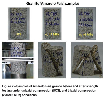
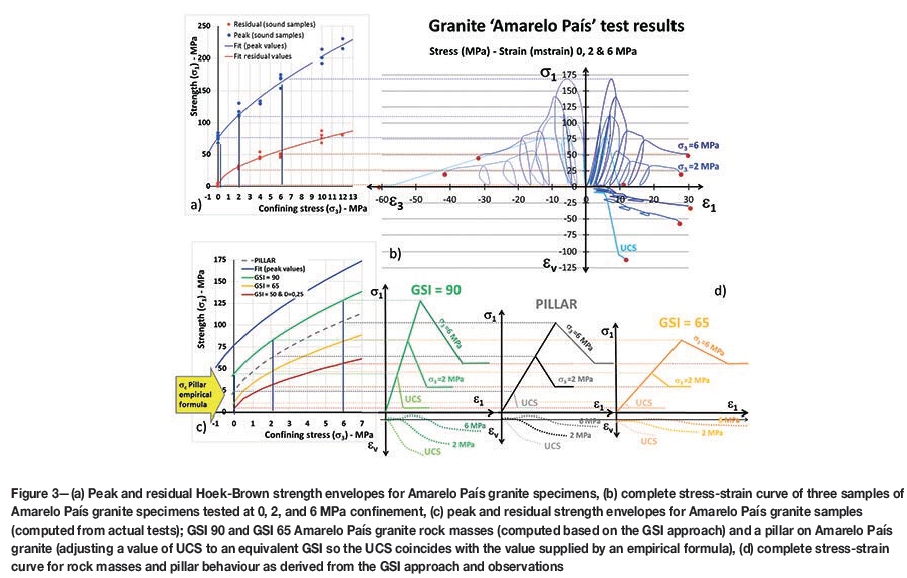
A previous study (Arzúa and Alejano, 2013) investigated the complete stress-strain response of intact granitic rock. This was done by using a servo-controlled press modified to control the confining pressure in the triaxial tests and to measure the volume of hydraulic fluid displaced from Hoek's triaxial cell so that it could be related to the volumetric strain of the rock sample. More than 20 unconfined and confined compressive tests were performed on Amarelo País granite samples (Figure 2). The results were plotted and studied in relation to the most relevant parameters, including elastic, strength, and post-failure parameters.
The peak and residual strength envelopes were fitted using regression analysis techniques (Figure 3a). Information regarding the post-failure behaviour was obtained based on the full stress-strain results (auej; aue3; and ev, ej) as shown in Figure 3b. In order to extend these observations to the behaviour of large-scale rock masses, the Hoek and Brown (1997) approach based on GSI (Marinos and Hoek, 2000) was adopted. According to Exdaktylos and Tsoutrelis (1993) and Cai et al. (2007) and our own observations (Arzúa, Alejano, and Walton, 2014), the residual strength of intact rocks, as interpreted from triaxial tests, could be similar to the that of jointed rock masses. It was also observed that the stress drop from peak to residual values, when confinement increases, results in a shallower slope (Figure 3b).
Statistical fitting of unconfined and triaxial strength results enabled the intact rock strength envelope (blue) to be fitted (Figure 3a and c) and estimation of the Hoek-Brown parameters of this rock as UCS= 76.59 MPa and m = 40.96. This, in turn, can be used to compute strength envelopes for different quality rock masses (e.g., GSI 90 or 65, following the GSI approach), shown in green and orange colours respectively in Figure 3c. It is also possible to back-analyse the GSI value that would make the UCS of the rock mass equal to that estimated according to pillar formulae. Thus, for a 4 m wide and 8 m high pillar, and using the Hedley and Grant (1972) formula opillar= 0.74 x ocix W0.5 x H-0.75, a compressive strength of 23.8 MPa is estimated for the pillar, equivalent to that for a rock mass with GSI 79. This would lead to a strength envelope shown by the dotted grey line in Figure 3c.
Based on the assumption of scale-independent residual strength discussed above, it is possible to estimate the complete stress-strain response of the rock mass for different rock qualities and for the pillar. This behaviour for three confinement levels is shown in Figure 3d. Note how a decrease in rock mass quality decreases dilation of the pillars. This dilation also becomes smaller as the confining stress increases. Although these estimates of pillar behaviour are first approximations only, they may provide insight on the effect of strapped pillars based on the strength testing of strapped rock specimens.
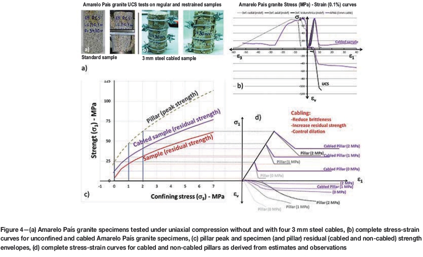
As a next step, we compared results obtained from the standard uniaxial strength test on Amarelo País granite specimens described above with results obtained from a specimen strapped using four steel cables of 3 mm thickness (Figure 4a and b). The complete stress-strain curves (Figure 4b) reflect similar trends to those observed for the Indiana limestone specimens. For the cabled specimen, dilation occurred in a more controlled fashion. Additionally, a significant residual strength, around 10 MPa was maintained by the strapped sample after 4% axial strain.
These results were used to estimate the residual strength of strapped specimens by fitting a GSI value, whereby the equivalent 'rock mass' uniaxial compressive strength was adjusted to that observed in the test as indicated by the observations of Cai et al. (2007). Accordingly, the estimated residual strength envelope for the cabled specimens and pillars (due to the fact that it is assumed that scale effects do not affect this strength) was obtained as the purple curve shown in Figure 4c. Similar to the description above, the peak pillar strength was obtained and the pillar behaviour (for a standard pillar and a strapped pillar) in terms of its complete stress-strain curve can be estimated for various confinement levels as shown in Figure 4d. Note that even if the pillars are unconfined, some confinement is usually present as shown by actual measurements (Maleki and Lewis, 2010; Tulu and Heasley, 2011) and numerical models (Duncan Fama, Trueman, and Craig, 1995).
The results presented in Figure 4 and associated considerations would indicate that strapping pillars with a reasonable number of steel cables does not affect their elastic (generally pre-peak) behaviour, whereas it does affect their post-failure behaviour by significantly increasing residual strength, controlling dilation, and slightly reducing brittleness. This increase in residual strength could possibly contribute to the stability of a room and pillar mine.
Description of the experimental room and pillar mine
General information about the mine
Initially mined in the early 20th century and again in the 1950s and 1960s, Santa Rosa is an old underground room and pillar mine. A haematite bed typically 2 m thick (but varying in thicknesses between 2 and 10 m due to thrust faulting) of Cambrian age is exploited. The current production is very small; around 10 000 t/a. The ore is crushed, classified, and sold as a paint additive.
The geological history of this sedimentary basin is complex. Locally, thrust faulting has thickened the bed in some locations, but the ore tends to follow a dip of around 15°. Some normal faults are present that limit the deposit in some locations and produce discontinuities in other areas. This makes the geology unpredictable, which together with the small production, causes mining to be concentrated in areas where the iron ore bed is considered to be the optimum thickness. This results in a number of scattered, irregular-shaped rooms being mined in the vicinity of the ramp. Planning of the future mining areas is difficult owing to the small budget associated with the small production and the geological complexity of the deposit. Future mining is therefore planned based on drilling from the stopes and drifts, and reserves are delineated roughly one year ahead of current mining.
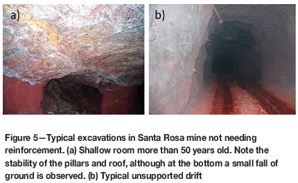
The rock mass in the immediate vicinity of the reef is bedded and contains four joint sets. This rock mass was originally highly discontinuous due to Carboniferous -age tectonic stresses (the Variscan or Hercynian orogeny). Subsequently, the rock was subjected to metamorphism of Alpine age that reassembled the rock mass and 'froze' the faults and joints. This has produced a good-quality rock mass (GSI in the range of 60-70). As a result, 4 m wide drifts and rooms up to 15 m long do not need to be supported. This is very convenient for reducing mining costs, and very few cases of instability (very local and small rockfalls) have been reported in these excavations (Figure 5).
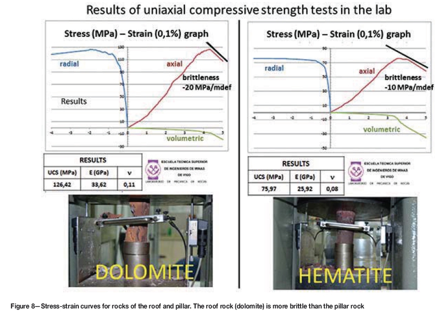
A laboratory programme which involved UCS and triaxial strength tests was carried out to characterize the rocks found in the mine (haematite ore and dolomite). In July 2011, the authors conducted a first stability assessment of the mine. The overall stability of the rooms and 50 identified pillars was assessed using empirical approaches and preliminary numerical simulations. The roofs of the rooms were deemed to be stable, with only minor local falls of ground observed. These are associated with a green shale layer that tends to swell when subjected to humid conditions.
Pillar strength was computed by means of the formula proposed by Hedley and Grant (1972):
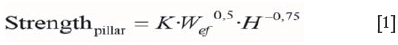
K was estimated by averaging the UCS test results on standard samples recovered in different areas of the mine, inverting the formula above, and finally performing a scale correction associated with the strength scale formula proposed by Hoek and Brown (1980) accounting for a representative elementary volume of a cylinder with a diameter of 200 mm as suggested by Martin et al. (2014). It is relevant to note that this approach produced an average K value of 0.65σo, equal to the estimate proposed by Esterhuizen et al. (2011) for sedimentary rock pillars in underground quarries. H refers to the height of the pillar and Weej is the effective width, which is computed for isolated pillars as (Malan and Napier, 2011):
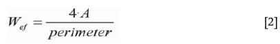
where A is the area of the pillar.
The load on the pillars is estimated based on tributary area theory, which relates the pillar stress to the pre-mining stress and the extraction ratio by:
where σPis the estimated pillar load, av is the vertical pre-mining stress (equal to depth of the pillar multiplied by the mean specific weight of the overburden), and e is the extraction ratio. It should be noted that this is only a crude first approximation as the mining areas are small with a number of nearby abutments. Equation [3] therefore overestimates the stress on the pillars.
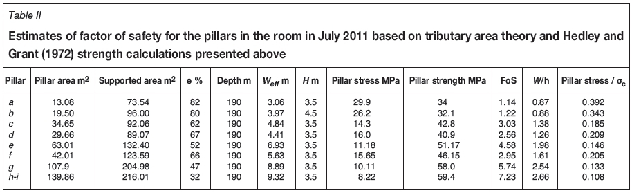
The factor of safety of the pillars is ultimately estimated as the ratio of pillar strength and average load. Only five pillars of more than 50 studied showed factors of safety smaller than 1.5. Two of these pillars were located in the deepest room of the mine (190 m deep) and were of irregular shape. These two pillars are discussed in more detail below.
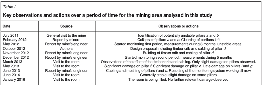
Description of the mining area where pillar strapping was used
The mining area of interest is located in the deepest part of the mine. Figure 6a illustrates the plan view of this area at the time of the stability study. The subsequent observations in this area are summarized in Table I. It can be seen in Figure 6a that pillars a and b in this room had small dimensions, which according to the miners was a result of overbreak. Photographs of these pillars at the date of the visit are shown in Figure 7.


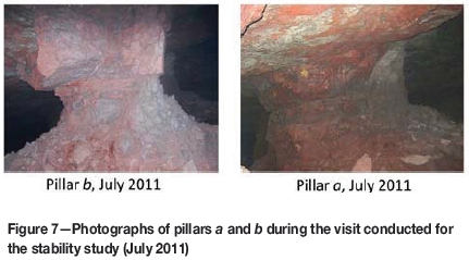
Factors of safety of 1.14 and 1.22 were estimated for pillars a and b. The other pillars appeared to be more stable, and this was confirmed by the higher factor of safety values (Table II). Pillar b was of particular concern due to the high density of joints in its lower part.
In the general stability study, it was observed that the post-failure behaviour of the haematite was more ductile (less brittle) than that of the dolomite rock of the roof and floor. Based on this consideration, it was evident that catastrophic pillar failure was not to be expected based on energy considerations (Figure 8) and according to Zipf (2001).
A few months after presenting the general stability study, the geometry of this mining area had changed substantially (cutting of pillars e, g, h, and i, see Figure 6b). It was reported by the mine in February 2012 that pillar b had collapsed, immediately followed by pillar a. Luckily, no other pillars were affected. Access to the area was limited due to safety regulations and a monitoring system with levelling control of various roof and pillar targets was established during May 2012.
A stability analysis of the unsupported roof span was performed (Figure 6b, where pillars a and b stood), showing compromised stability according to Mathews' stability graph method (Mathews et al., 1980; Potvin, 1988). It was therefore recommended that a concrete and timber crib be built in the middle of the unsupported span (between the locations of collapsed pillars a and b). This timber crib needed a concrete base due to the fact that the area was to be flooded. It was also decided to strengthen pillar d with cable strapping as it was likely to be overloaded after the collapse of pillars a and b. The estimated factor of safety on this pillar was 1.23 after the collapse of pillars a and b.
The crib was designed and built within a few months, as Figure 9 illustrates. It was designed to avoid instability of the roof as well as to distribute vertical stress to the abutment of the room, avoiding overloading of the nearby pillars. Oak and pine wood railway ties or sleepers were found in the market with a uniaxial compressive strength over 30 MPa and Young's modulus in the range 8 to 10 GPa. During the preparation for this construction, the monitoring system was damaged. During the control period (from May to August, 2012), maximum vertical convergence rates of approximately 2 mm/month were measured at the east side of pillar d.
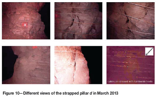
The lower part of pillar d was strapped with six steel torsion cables of 1 cm diameter separated by approximately 30 cm. These were fixed and stressed by means of turnbuckle hooks (Figure 10). Shortly after their installation, small cracks were observed and the cables appeared to be under tension.
The remedial measures were completed by December 2012. Pumping was also stopped in the area due to mine requirements. The damaged monitoring system was reinstalled with locating targets in some pillars and roof positions. Levelling and measuring was carried out every month. For the period from December 2012 and May 2013, the data illustrated displacements of less than 3 cm on the pillar surfaces and lowering of the roof of around 1 cm in a location between the timber crib and pillar d. Movement of measurement bases prevented further measurements and some falls of ground was observed. A further visit to the mine was therefore planned for March 2013.
During the visit in March 2013, it was observed that the cables on pillar d seemed to be effective. Even though some cracks appeared in the pillar, the cables were able to retain most of the detached blocks, thereby increasing confinement in the pillar (Figure 10). Small pieces of rock fell between the cables, so it was clear that for future strapping of pillars, it would be advisable to wrap the pillar in mesh before installing the cables.
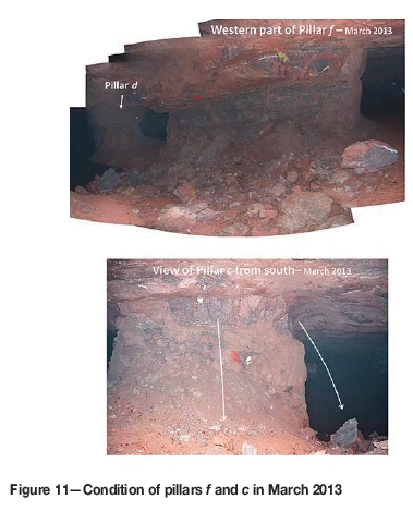
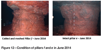
A further visit in May 2013 was conducted to examine the condition of the pillars. Pillars e and h were intact, but slight scaling of pillars i and g was observed. Pillar c showed signs of more severe scaling and two significant blocks fell from this pillar (0.3 m (1 ft) side cubes) (Figure 11). The stability of pillar/was particularly poor, with significant scaling on its western side. This reduced its width - and consequently its section - by around 1 m (Figure 6c and 11).
Based on these observations, it was recommended that pillars/ and c be strapped with mesh and cabling. This work was completed in June 2013. Additionally, the monitoring system was reset and displacement measurements were recorded every two to three months during the following 2½ years.
No significant instability was reported during the following year and a follow-up visit was made to the site during June 2014. Photographs of the strapped pillar/and of the intact pillar e taken during this visit ate shown in Figure 12. No movements or pillar instability was recorded during this inspection and it appears that the pillar support was functioning as intended. A further visit was conducted in June 2015 with similar observations, and it was decided to start filling this excavation with available waste material (scarce in this mine). A final visit in January 2016 indicated no further instability problems.
Data recorded by the monitoring system
The harsh conditions in underground mining environments make it particularly difficult to maintain these systems. Displacement monitoring systems consisting of laser measuring devices and a number of targets are particularly prone to damage as the targets can be accidently moved or disturbed. This happened twice in this particular case study.
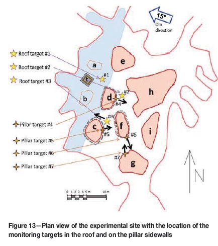
As described above, a monitoring system was installed in May 2012 after the collapse of pillars a and b. This included targets on the pillars (visible in Figures 10 and 11 on pillars d and c) and on the roof in the more unstable areas as shown in the sketch in Figure 13. Three useful measurements were made with this initial system, giving vertical deformations rates in the roof up to 2 mm/month near pillar d (which was not strapped at the time). Two further measurements were recorded. Unfortunately the recording base shifted after this and further records were unreliable. A maximum displacement just over 1 cm was estimated for the period from May 2012 to November 2012, when pillar d was strapped.
The monitoring system was reinstalled in December 2012 using most of the same targets. At this stage the timber crib and strapping of pillar d. was completed. Five groups of monthly measurements were recorded before the system was lost again (caused by falls from pillar ƒ). Maximum vertical velocities in the roof between pillars c and ƒ of up to 2 mm/month were recorded. Pillar ƒ was scaling at the time, so this deformation is interpreted as the result of this pillar slowly failing. In contrast, the vertical velocity near the strapped pillar d was now reduced to approximately 0.3 mm/month. It is therefore deduced that the strapping of pillar d effectively improved the stability of this pillar.
A third period of measurement started in June 2013 after the strapping of pillars ƒ and c. The measurements recorded using the targets shown in Figure 13 are presented in Figure 14 for the roof and Figure 15 for the pillars. The period of recording was 700 days, after which the area seemed to reach a new state of equilibrium. A maximum vertical displacement of 1.5 cm for this period was observed in the roof.
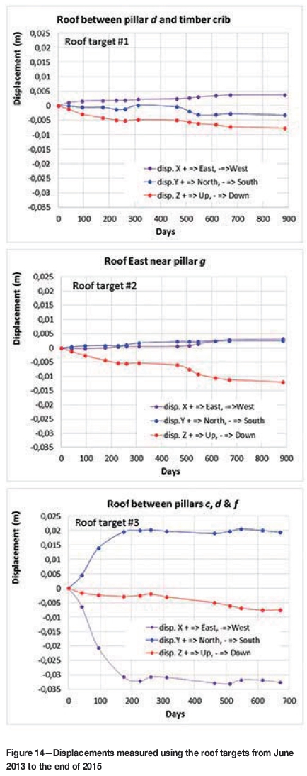
In conclusion and as summarized in Table III, in the four-year period, a maximum total roof displacement of less than 5 cm was estimated. The iron ore bed in this area is 4 m thick, resulting in a vertical strain of the pillars of around 1.25% (12.5 millistrain). This is considered feasible, particularly for the strapped pillars, as the laboratory results indicated that values up to 5% are possible.
Graphical representation of pillar instability
A useful method to represent the stability of pillars was proposed by Martin and Maybee (2000) and consists of plotting pillars in terms of the ratios (pillar load/UCS) and (W/H) for a particular pillar height (4 m in this case). Such a graph was plotted for the pillars at the experimental site and is presented in Figure 16. A pillar is considered stable according to a particular empirical strength formula if it plots below the line of that formula.
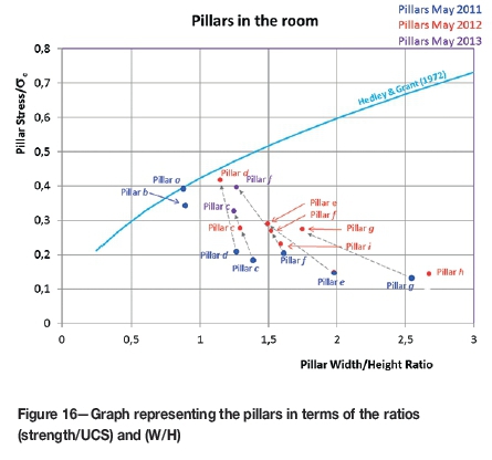
The state of pillars in May 2011 (Figure 6a) is represented by a blue colour in Figure 16. This indicates that the pillars a and b were only slightly below the Hedley and Grant (1972) strength and therefore close to being unstable. The state of the other (some reshaped) pillars after the collapse in May 2012 (Figure 6b) is represented by the red colour in Figure 16. Pillar d appears to be close to instability and therefore required strapping. Furthermore, in May 2013 the state of pillar c and particularly ƒ (the only one that had significantly changed because of the reduction of its size due to the scaling) also justified strapping. It is clear that this graphic representation, in conjunction with in situ observations, can be a useful and simple method to quantify and investigate the stability of underground pillars.
Finally, it is relevant to remark that in the process of development of this study, some assumptions were made out of necessity. This has to be often the case in large-scale rock pillar stability, where a certain degree of uncertainty is always to be expected.
Discussion
As discussed above, the objective of the paper is not to propose a new pillar design method, but to describe a remedial support method for damaged or potentially unstable pillars. The technique was shown to be very useful in the Santa Rosa mine where the span of the experimental mining area was small. It should be noted that the proposed method will not be universally applicable as it will not prevent creep or extrusion phenomena. Furthermore, a recent collapse in a shallow hard-rock room and pillar mine in Africa indicated that even very heavy strapping of pillars will not prevent a collapse if the instability occurs on a mine-wide scale. In this particular mine, a thick shear layer with clay-like infilling was encountered in the deeper parts of the mine after very large spans had already been mined. This layer is shown in Figure 17. The mine started collapsing in the deeper areas and the subsequent load transfer also affected the pillars in the shallower areas. It was then discovered that the shear zone occurred in the footwall in some of these areas. It was decided to strap the key pillars protecting the main roadways with very heavy support. The support consisted of a layer of shotcrete, bolting, mesh, steel strapping, and a further layer of shotcrete. This is shown in Figure 18. Unfortunately, this support did nothing to arrest the eventual collapse (Figure 19) and at least half of the mine and the main access roadways were lost.
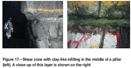
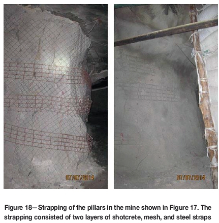
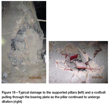
Figure 20 (modified from Brady and Brown, 2006) shows typical pillar failure modes. If pillars are cut in massive rock with no weak contacts with the floor and roof, failure will occur by spalling from the pillar surfaces (Figure 20a). This leads to a progressive reduction in the width of the pillar and will increase the stress on the pillar. If the width/height ratio of a pillar is small, an inclined shear failure could develop (Figure 20b). If there are weak contacts between the pillar and the hangingwall and footwall, there will typically be internal axial splitting of the pillar (Figure 20c). If there is a joint set (or more than one) with a dip angle larger than the angle of friction, the pillar can yield due to slipping on the fractures (Figure 20d). If the joints are parallel to the principal axis of loading, the pillar may fail by buckling (Figure 20e).


It is hypothesised that for the first five cases in Figure 20, cabling will contribute to an increase in pillar stability. The deformation of the pillar will tension the cables, increasing the confining stress and, consequently, the pillar strength.
This concept should nevertheless be further tested for different conditions encountered in a variety of mines. If there is a weak material forming intermediate layers or filling the discontinuities as shown in Figure 20f, the proposed approach may prove ineffective as was illustrated by the mine collapse described above. It should be noted that for this particular collapse, some pillars may have failed according to the mechanism in Figure 20d where the shear zone was some distance into the footwall. It is very clear from this particular case study that no amount of pillar reinforcement will be successful in the case of such a large mine-wide instability.
Conclusions
Failing pillars may be encountered in room and pillar mines unless a very conservative design approach is followed. Remedial measures (shotcrete, rockbolting, strapping) have been adopted in some cases for failing pillars, but the success of these is doubtful based on reports in the literature. In this paper we investigated the usefulness of an inexpensive pillar strapping method that may assist in stabilizing individual failing pillars in isolated areas. Installing a number of cables around the pillar will increase its strength and ductility as it slightly increases the confinement, and minimize ongoing degradation.
Compressive strength tests were conducted in the laboratory on cabled rock specimens. This illustrated that the cabling increases the residual strength and ductility, which allows for large controlled deformations instead of catastrophic failure. The dilation of the cabled rock specimens was less than in comparable tests on unconfined specimens. The cabling did not affect the elastic properties and peak strength of the samples. As a theoretical exercise, the laboratory-scale observations were extended to larger scales by assuming that the residual strength is not dependent on scale and adopting the Hoek and Brown (1997) approach based on GSI (Marinos and Hoek, 2000).
As a first trial, this method was applied in a small haematite room- and- pillar mine. A room located at a depth of 190 m, which contained some scaling pillars, was stabilized by using meshing and cabling on the unstable pillars. The room remained stable for a period of 900 days when the final observations were made.
The method of strapping pillars using mesh and cabling seems useful for stabilizing individual pillars in areas where most of the other pillars are stable and the total mining spans are small. This concept should nevertheless be further tested for different conditions encountered in a variety of mines. If there is a weak material such as a clay layer traversing the pillar, the proposed approach may prove ineffective, as was illustrated by a recent mine collapse in Africa.
Acknowledgements
The authors wish to thank the Spanish Ministry of the Economy and Competitiveness for partial funding, awarded under Contract Reference No. BIA2014-53368-P, partially financed by ERDF funds from the EU. The mining engineers of Santa Rosa Mine are also acknowledged for their contribution to the case study presented in this manuscript.
References
Alejano, L.R., GarcIa-Bastante, F., Taboada, J., and Migliazza, R. 2012. Design of room and pillar exploitations of non-expensive minerals and ornamental rocks in Spain. Harmonising Rock Engineering and the Environment - Proceedings of the 12th ISRM Intermational Congress on Rock Mechanics. pp. 1453-1456. [ Links ]
Arzúa, J. and Alejano, L.R. 2013. Dilation in granite during servo-controlled triaxial strength tests. International Journal of Rock Mechanics and Mining Sciences, vol. 61. pp. 43-56. [ Links ]
Arzúa, J., Alejano, L.R., and Walton, G. 2014. Strength and dilation of jointed granite specimens in servo-controlled triaxial tests. International Journal of Rock Mechanics and Mining Sciences, vol. 69. pp. 93-104. [ Links ]
Bieniawski, Z.T. 1992. A method revisited: coal pillar strength formula based on filed investigations. Workshop on Coal Pillar Mechanics and Design. US Bureau of Mines, IC 9315. [ Links ]
Brady, B.H.G. and Brown, E.T. 2006. Rock Mechanics for Underground Mining. 3rd edn. Springer. [ Links ]
Cai, M., Kaiser, P.K., Tasaka, Y., and Minamic, M. 2007. Determination of residual strength parameters of jointed rock masses using the GSI system. International Journal of Rock Mechanics and Mining Sciences, vol. 44, no. 2. pp. 247-265. [ Links ]
Chase, F.E., Zipf, R.K., and Mark, C. 1994. The massive collapse of coal pillars: case histories from the United States. West Virginia University, Morgantown, WV. pp. 69-80. [ Links ]
Dismuke, S.R. Forsyth, W.W., and Stewart, S.B.V. 1994. The evolution of mining strategy following the collapse of the Window Area at the Magmont Mine, Missouri. Proceedings of the CIM Annual General Meeting, District 6, Metal Mining, CIM Montreal, 1994. pp. 3-8. [ Links ]
Duncan Fama, M.E., Trueman, R., and Craig, M.S. 1995. Two- and three- dimensional elasto-plastic analysis for coal pillar design and its application to highwall mining. International Journal of Rock Mechanics and Mining Sciences, vol. 32. pp. 215-225. [ Links ]
Esterhuizen, G.S., Dolinar, D.R., and Ellenberger, J.L. 2011. Pillar strength in underground stone mines in the United States. International Journal of Rock Mechanics and Mining Sciences, vol. 48, no. 1. pp. 42-50. [ Links ]
Esterhuizen, G.S., Dolinar, D.R., Ellenberger, J.L., and Prosser, L.J. 2011. Pillar and roof span design guidelines for underground stone mines. Information Circular 9526. NIOSH. Pittsburgh, USA. [ Links ]
Esterhuizen, G.S. 2006. An evaluation of the strength of slender pillars. SME Annual Meeting, St. Louis, Missouri. [ Links ]
Exadaktylos, G.E. and Tsoutrelis, C. E. 1993. Scale effect on rock mass strength and stability. Scale Effects in Rock Masses 93. Pinto da Cunha, A. (ed.). Balkema, Rotterdam. [ Links ]
Grgic, D., Hommand, F., and Hoxha, D. 2003. A short- and long-term rheological model to understand the collapses of iron mines in Lorraine, France. Computers and Geotechnics, vol. 30, no. 7. pp. 557-570. [ Links ]
Hedley, D.G.F. and Grant, F. 1972. Stope-and-pillar design for Elliot Lake Uranium Mines. Bulletin of the Canadian Institute of Mining and Metallurgy, vol. 65. pp. 37-44. [ Links ]
Hedley, D.G.F., Roxburgh, J.W., and Muppalaneni, S.N. 1984. A case history of rock-bursts at Elliot Lake. Proceedings of the 2nd International Conference on Stability in Underground Mining. Szwilski, A.B. and Brawner, C.O. (eds). Society of Mining Engineers. pp. 210-234. [ Links ]
Hoek, E., and Brown, E.T. 1997. Practical estimates of rock mass strength. International Journal of Rock Mechanics and Mining Sciences, vol. 34, no. 8. pp. 1165-1187. [ Links ]
Hustrulid, W. 1976. A review of coal pillar strength formulas. Rock Mechanics, vol. 8. pp. 115-145. [ Links ]
Jaiswal, A. and Shrivatva, B.K. 2009. Numerical simulation of coal pillar strength. International Journal of Rock Mechanics and Mining Sciences, vol. 46, no. 4. pp. 779-788. [ Links ]
Khair, A.W. and Peng, S.S. 1985. Causes mechanisms of massive pillar failure in a southern West Virginia coal mine. Mining Engineering, vol. 37. pp. 323-328. [ Links ]
Lunder, P.J. and Pakalnis, R. 1997. Determination of the strength of hard rock mine pillars. Bulletin of the Canadian Institute of Mining and Metallurgy, vol. 68. pp. 55-67. [ Links ]
Madden, B.J., Canbulat, I., and York, G. 1998. Current South African coal pillar research. Journal of the South African Institute of Mining and Metallurgy, vol. 98. pp. 7-10. [ Links ]
Malan, D.F. and Napier, J.A.L. 2011. The design of stable pillars in the Bushveld Complex mines: a problem solved? Journal of the Southern African Institute of Mining and Metallurgy, vol. 111. pp. 821-836. [ Links ]
Maleki, H. and Lewis, J.C. 2010. Verification of in situ pillar strength for Utah coal seams. Proceedings of the 44th US Rock Mechanics Symposium and 5th U.S-Canada Rock Mechanics Symposium, Salt Lake City, 27-30 June 2010. American Rock Mechanics Association. 15 pp. [ Links ]
Mansurov, V.A. and German, V.I. 2009. Preparation and causes of major collapse at Annenskiy Mine (Kazakhstan). Rock Engineering in Difficult Ground Conditions - Soft Rocks and Karst: Proceedings of EUROCK2009 - the Regional Symposium of the International Society for Rock Mechanics. pp. 809-814. [ Links ]
Marinos, P. and Hoek, E. 2000. GSI: A geologically friendly tool for rock mass strength estimation. Proceedings of the GeoEng2000 Conference. Technomic, Lancaster, PA. pp. 1422-1442. [ Links ] .
Martin, C.D., Lu, Y., Lan, H., and Christiansson, R. 2014. Numerical approaches for estimating the effect of scale on rock mass strength. Proceedings of the 7th Nordic Grouting Symposium and 2nd Nordic Rock Mechanics Symposium.. Ghotemburg, 13-14 November 2014. pp. 93-106. [ Links ]
Martin, C.D. and Maybee, W.G. 2000. The strength of hard rock pillars. International Journal of Rock Mechanics and Mining Sciences, vol. 37. pp. 1239-1246. [ Links ]
Mathews, K., Hoek, E., Wyllie, D.C., and Stewart, S.B.V. 1980. Prediction of stable excavation spans for mining at depths below 1000 metres in hard rock. Report to Canada Centre for Mining and Energy Technology (CANMET), Department of Energy and Resources, DSS File No. 17SQ.23440-0-90210. Ottawa, [ Links ]
Murali Mohan, G., Sheorey, P.R., and Kushwaha, A. 2001. Numerical estimation of pillar strength in coal mines. International Journal of Rock Mechanics and Mining Sciences, vol. 38, no. 8. pp. 1185-1192. [ Links ]
Potvin, Y. 1988. Empirical open stope design in Canada. PhD thesis, Department of Mining and Mineral Processing, university of British Columbia. [ Links ]
Salamon, M.D.G. and Munro, A.H. 1967. A study of the strength of coal pillars. Journal of the South African Institute of Mining and Metallurgy, vol. 68. pp. 56-67. [ Links ]
Siwak, J.M. 1984. Carrières de craie du Nord de la France. Comportement des piliers et confortation par gunitage. (Shale quarries in northern France. Pillar behavior and shotcrete support). PhD thesis. Université des Sciences et Techniques de Lille. (In French). [ Links ]
Tulu, I.B. and Heasley, K.A. 2012. Investigating abutment load. Proceedings of the 31st International Conference on Ground Control, Morgantown, WV. pp 150-159. [ Links ]
Van Der Merwe, N. 2006. Beyond Coalbrook: what did we really learn? Journal of the Southern African Institute of Mining and Metallurgy. vol. 106. pp. 857-868. [ Links ]
Wang, J.-A., Shang, X.C., and Ma, H.T. 2008. Investigation of catastrophic ground collapse in Xingtai gypsum mines in China. International Journal of Rock Mechanics and Mining Sciences, vol. 45. pp. 1480-1499. [ Links ]
Wojtkowiak, F., Rai, M.A., and Bonvallet, J. 1985. Experimental studies in laboratory of different reinforcement methods to be applied on small mining pillars. Bulletin of the International Association of Engineering Geology, vol. 32. pp. 131-138. (In French). [ Links ]
Zingano, A.C., Koppe, J.C., and Costa, J.F. 2004. Colapso de pilares em mina subterrânea de carvão - mina do Barro Branco - Santa Catarina (Pillar collapse in an underground coal mine). Congresso Brasileiro de Mina Subetrrânea, Belo Horizonte. (In Portuguese). [ Links ]
Zipf, R.K. 2001. Toward pillar design to prevent collapse in room-and-pillar mines. 108th Annual Exhibit and Meeting, Denver, CO. Society for Mining, Metallurgy and Exploration, Littleton, Co. [ Links ]
Paper received May 2016
Revised paper received Aug. 2016
* Corresponding Author.

