


Services on Demand
Article
 English (pdf)
 Article in xml format
 Article references
Indicators

Related links
-
 Cited by Google
 -
 Similars in Google
Share

 Permalink
Journal of the Southern African Institute of Mining and Metallurgy
On-line version ISSN 2411-9717
Print version ISSN 2225-6253
J. S. Afr. Inst. Min. Metall. vol.117 n.4 Johannesburg Apr. 2017
http://dx.doi.org/10.17159/2411-9717/2017/v117n4a3
STUDENT PAPERS
Installation of resin-grouted rockbolts in hard rock mining: challenges and solutions for improved safety
T.G. Maepa; T. Zvarivadza
School of Mining Engineering, University of the Witwatersrand, Johannesburg, South Africa
SYNOPSIS
The creation of mine excavations alters the stress distribution in the surrounding rock mass. In modern mining, resin-grouted rockbolts are used as a means of support in order to redistribute stresses and reestablish equilibrium in the rock mass. The success of resin-grouted rockbolting depends on the design of the system and the correct installation of the support units.
The support design and rockbolt installation procedure at a platinum mine in the Bushveld Complex were investigated. A number of issues that resulted in poor installation were identified, including resin admixture, incorrect length and orientation of support holes, over- or under-spinning of the resin, and incorrect rockbolt tensioning. The support design used at the mine was reviewed and its limitations identified. A number of recommendations were made for optimizing the support design by reducing the diameter of the drill bit and reducing the length of the support holes. These changes will enable the mine to use different combinations of resin capsules. Implementation of the proposed changes will lead to a significant reduction in the cost of installation per support hole, as well as improve productivity and safety.
Keywords: resin-grouted rockbolts, hard rock mining, installation procedure, safety, optimization, cost saving.
Introduction
The creation of any mine excavation disturbs the virgin state of stress in the Earth's crust. This results in stress concentrations that interfere with the stability of the rock mass surrounding the excavation. It is essential to modify the internal behaviour of the rock mass surrounding excavations in order to reinforce the ground and stabilize excavations. Resin-grouted rockbolts are extensively used for this purpose. Esterhuizen (2014) stated that when effectively installed, the rockbolt exerts a clamping force and a bonding strength that keeps the rock mass together. This increases the cohesive strength of all discontinuities in the rock mass and enhances the stability of the excavation. Poorly designed and installed ground support is ineffective and constitutes a safety hazard. It is therefore crucial for every mine to ensure that any form of ground support is designed and installed correctly. This research evaluates the installation of resign-grouted rockbolts and identifies challenges and solutions for improved safety as observed at an operating hard rock mine. The support design used at the mine was reviewed and the design parameters optimized. The outcomes will enhance the efficiency of support and minimize the costs associated with the installation of resin-grouted rockbolts.
Mining environment and study background
The studied mine is situated in the Bushveld Complex of South Africa. It comprises two zones-a shallow more ductile zone and a deeper less ductile zone which is more stable. At full production, a combination of conventional breast mining, room and pillar, and area-specific mining methods will be used to extract the orebody.
Inspection of loose, exposed rockbolts during the support audits indicated that around 250 mm of the bolts had not been covered with resin. Furthermore, a review of the monthly record of the number of resin-grouted rockbolts installed at the mine indicated that a significant proportion of the bolts are installed incorrectly. The numbers of resin-grouted rockbolts installed at the mine in the last quarter of 2015 are presented in Table I.
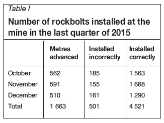
About 10% of the resin-grouted rockbolts that were installed in the last quarter of 2015 were installed incorrectly. The consequences of poor support design and installation are rockfalls, increased support costs, and delays in production. Poor design and incorrect installation of any form of support in any underground mine introduces adverse risks in the mining environment (Henning and Ferreira, 2010).
Based on the information from support audits and the mine records, it was clear that the mine had pronounced design and operational inefficiencies. To ensure that the support design and installation processes do not pose any adverse risk to the mine or personnel, a full investigation was carried out.
Justification for the research
The authors noted that the majority of the recorded faulty rockbolt installations were visible to the observer during support audits (e.g. protruding rockbolts). A significant number of faulty rockbolts, i.e. under-tensioned or over-tensioned bolts and bolts with insufficient resin, are not recorded as faulty since the entire installation process needs to be observed in order for these faults to become apparent. It was therefore necessary to go underground and obtain essential information to help the mine to address the design and operational inefficiencies. The findings of this investigation will potentially help the mine, and similar mines, to improve the efficiency, and reduce the costs, of support installation, as well as improve safety and productivity (Ferreira, 2012).
Objectives
The main objectives of the investigation include:
► Identifying and addressing the challenges that lead to poor installation of resin-grouted rockbolts at the mine
► Reviewing the support design used at the mine and identifying its limitations
► Optimizing the support design parameters
► Making recommendations that can be used to improve the support design and the installation process.
Scope of the study
The data used in this investigation was collected in the development ends in block 9 and block 12 of the mine. The mine uses three different forms of bolt support, namely resin-grouted rockbolts, split sets, and mechanical anchor bolts. However, the study is limited to the use of resin-grouted rockbolts since these are the main form of bolt support used in the development ends.
Relevant background literature
To effectively understand the research problem, the literature related to the area under investigation was critically summarized. The literature surveys permitted the authors to identify the strengths and weaknesses in previous research work.
The basis for relying on coal literature in an investigation that is based on a platinum mine
Shallow underground mines are characterized by a significant tensile zone in the hangingwall, which presents the risk of hangingwall failure. Cawthorn (2007) stated that the different minerals in the Bushveld Complex crystallized at different temperatures, forming a layered structure. Due to the tensile zone in the hangingwall, it is possible for the rock strata to separate, resulting in falls of ground. Therefore, the layering of rocks in the shallow areas of the Bushveld Complex can be compared with the stratified sedimentary rocks found in coal mining environments. Resin-grouted rockbolts were first introduced in the coal mining industry, and the ability to create stable beams in underground coal mines using fully grouted rockbolts led to the adoption of this support system in platinum mines.
The use of resin-grouted rockbolts in hard rock underground mines
The fully-grouted rockbolt support system consists of a ribbed tendon that is anchored in geotechnically sound rock using a full-length column of resin that is obtained from resin capsules (Barrett, 2006). During installation, the rotation of the rockbolt mixes the components of the resin capsules. When the two components are mixed correctly, the resin will set and hold the rockbolt in the support hole, resulting in an effective anchorage (Barrett, 2006). The fully-grouted rockbolt support system is a stiff form of support, which is highly recommended for shallow mines such as the one studied. The stiffness of the support system depends on the load transfer mechanisms between the resin, the rock, and the bolt (Mark, 2000). Rockbolts were initially grouted using a single type of resin, but the inherent inefficiencies of this led to the establishment of the dual system, i.e. the slow/fast resin combination (Varden and Villaescusa, 2006). This system, which is used at the mine, employs a fast-setting resin at the toe of the support hole and a slow-setting resin towards the collar, thus combining the advantages of both resins. Henning and Ferreira (2010) recommended resin-grouted rockbolts mainly for rocks without widely open discontinuities or voids that will cause resin loss, rocks without continuous water runoff problems, and for long-term support in thinly bedded roof strata.
Reinforcement mechanisms of rockbolts
Rockbolts serve the purpose of binding together broken or stratified rock layers to forestall falls of ground (Esterhuizen, 2014). In order to achieve this objective, four basic roofbolting mechanisms were developed (Chen, 1994):
► Simple skin support
► Suspension mechanism
► Beam building mechanism
► Keying of blocky and highly fractured ground.
The studied mine is characterized by insignificant horizontal clamping forces that are required to keep the rock mass intact in order to generate a self-supporting beam (Gamboa and Atrens, 2003). The resin-grouted rockbolts are used at the mine for both suspension and beam-building mechanisms. The rockbolts are also primarily used for keying of blocky and highly fractured rock masses.
Optimization of support design parameters
Chen (1994) stated that any inadequacies in the design of a support system may result in failure of underground excavations. On the other hand, a conservative design will increase costs. It is very important to optimize the support design parameters in order to maximize the support efficiency and minimize the costs associated with rockbolting. The main parameters to consider when designing a satisfactory rockbolting system include:
► Bolting angle
► Bolt length and diameter
► Bolt spacing
► Annulus size.
Installation quality
When resin-grouted rockbolts are incorrectly installed, at best they are ineffective, and at worst they provide a false sense of security. Unfortunately, monitoring of most modern rocksupport systems is challenging (Henning and Ferreira, 2010). In the case of fully-grouted rockbolts such as those used at the studied mine, Barrett (2006) and Mark (2000) suggest that potential installation problems may include:
► Defective grout
► Defective support hole
► Poorly mixed grout
► Defective rockbolts.
Research approach
An extensive literature study of previous work on the use of resin-grouted rockbolts in underground mining operations was carried out. This information was supplemented by inputs from underground support crews and members of the rock engineering department at the mine. Planned task observations (PTOs) were carried out regularly and integrated with inputs from different field experts. The authors further analysed the existing data at the mine (reports, records etc.) and consulted with the manufacturers of the resin capsules and rockbolts used at the mine.
Results and analysis
Mine support design review
The support standard of the mine was reviewed in order to ascertain the effectiveness of the support system. The main factors that were reviewed, as suggested by the literature survey, included the design length and diameter of the rockbolts, the design length and diameter of the support holes, the annulus size, and the resins that are used.
Bolt length
The rock engineering department at the mine uses the formula suggested by Barton for estimating the required length of rockbolts. The formula (in the absence of statistical data reflecting the height of rock requiring support) is as follows:
L= (2+0.15B)/ESR
where L is the bolt length, ESR is the safety factor related to the importance of the opening, and B is the excavation width (Barton, Lien, and Lunde, 1974). Thus for a tunnel with a maximum span of 8 m and a mean ESR value of 1.8 the required bolt length is 1.8 m. However, the standard bolt used at the mine is 2.4 m long. This bolt length takes into account the extra threaded portion of the bolt (100 mm) and the maximum allowable protruding length of the bolt for safety reasons (300 mm).
Bolt diameter
The diameter of the rockbolt is crucial in support design since it influences the yield strength of the bolt (Mark, 2000). Based on ρ, the density of the pyroxenite hangingwall (2 800 kg/m3),g, the gravitational acceleration (9.81 m/s2), and h, the maximum fallout thickness of 1.5 m, the required support resistance at the mine was determined to be 42.0 kN/m2 using the following formula:
SR = ρ χ g χ h
The spacing of the support holes is 2 m on dip and 2.5 m on strike, resulting in a bolt tributary area of 5 m2. Therefore, the minimum capacity required from a rockbolt in order to provide a safety factor of unity is 210 kN (42.0 kN/m2 χ 5 m2). The mine uses model Y20 rockbolts manufactured by Videx Mining Products (Pty) Ltd. This model has diameters ranging from 24-28 mm and a maximum capacity of 240 kN. This results in a SF of 1.1. The diameter of the bolt, based on the mine's annulus design, was chosen to be 25 mm.
Length and diameter of the support hole
The design length of the support holes at the mine is 2.4 m. The mine uses the R32 χ He χ 25 χ R25 χ 2.75 drill steel, which gives an effective drill length of 2.45 m. The support holes at the mine are drilled using a drill bit with a diameter of 32 mm.
Annulus size
Hagan (2003) stated that the relationship between the diameter of the support hole and the diameter of the rockbolt has a large effect on the efficiency of the reinforcement. Since the design diameter of the rockbolt is 25 mm, the design annulus size is 7 mm. According to the mine support standard, the required annulus size should not be greater than 10 mm. The design annulus size of 7 mm is within the required range as stipulated in the mine's code of practice. However, this is outside the manufacturer's recommended optimal design annulus size of between 3-4 mm. From this observation, the support design at the mine is not optimized and will result in inefficiencies in support.
Resins
Each support hole will have two fast-setting resin capsules (product code: FC2550060) and two slow-setting resin capsules (product code: FC25500510). The resin capsules are 500 mm long and 25 mm in diameter.
The summary of the mine's standard support design is:
► Bolt length: 2 400 mm (threaded portion is 100 mm)
► Bolt diameter: 25 mm
► Support hole length: 2400 mm
► Support hole diameter: 32 mm
►Resin capsule size: 500 mm by 25 mm.
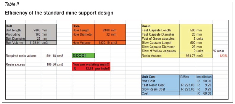
The Andre Se Resin Anchor calculator software is used at the mine to determine efficiency of support based on the relationship between the sizes of the support hole, the rockbolt, and the resin capsules. Table II shows the efficiency of the mine support design based on this calculator.
The standard mine support design is efficient in terms of support. The rockbolts are fully grouted with an excess resin mix of 23% per hole. Based on the standard support design, the mine is wasting resin in each support hole. The mine is losing a total of R12.61 per hole when installation is done effectively. However, the loose and exposed rockbolts that were inspected were not fully grouted.
Main findings of the support design study
PTOs and inputs from field experts enabled the authors to gather information which was then compared with the standard mine support design. The main differences between the study findings (actual design) and the standard mine support design (planned design) are presented in Table III.
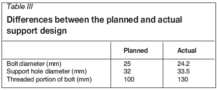
The actual diameter of the support holes (33.5 mm) is greater than the design diameter (32 mm). This is because the drill bits ream the holes. Tadolini (1998) has shown that reaming of the holes increases the design diameter by a maximum of 5%.
Summary of the authors' findings:
► Bolt length: 2 400 mm (threaded portion measured 130 mm)
► Bolt diameter: 24.2 mm on the bolt and 25 mm on the ribs
► Resin capsule size: 500 mm by 25 mm
► Support hole diameter: 33.5mm (32 mm diameter drill bits plus 5% hole reaming).
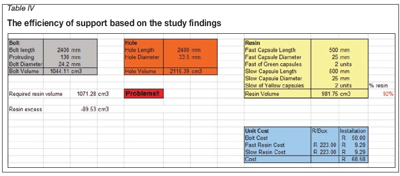
Table IV shows the efficiency of support based on the study findings, assuming that the length of the support hole is 2.4 m.
The support system has significant problems. Each support hole requires an additional 8% resin to be fully encapsulated and to offer maximum anchorage of the bolt. This is why around 250 mm of the rockbolts was not encapsulated with resin.
Optimizing the support design
In practice, the support holes require 8% more resin per hole. Possible solutions to this problem would be to increase the size of the rockbolts, increase the sizes of the resin capsules, or reduce the sizes of the support holes. Increasing the sizes of the rockbolts and resin capsules will have serious cost implications. Therefore, the size of the support hole should be reduced. Many authors have suggested different optimal ranges of annulus size. The manufacturer of the resin capsules that are used at the mine suggested an optimal design annulus size between 3 and 4 mm, while Hagan (2003) suggested an optimal practical annulus size between 4 and 6 mm. The specifications from the manufacturer also state that the optimal length of the support holes for the resin bolt installation process should be 50-60 mm shorter than the bolt length.
The support holes should be drilled to an optimal length of 2.35 m with a drill bit 28 mm in diameter. This will result in a design annulus size of 3.8 mm, which is within the manufacturer's recommendations of between 3 and 4mm. Taking into account the effect of reaming, the final diameter of the support holes will be 29.5 mm. This results in a practical annulus size of 5.8 mm, which is also within the optimal practical annulus size between 4 and 6 mm as suggested by Hagan (2003).
Summary of the optimal support design:
► Bolt length: 2 400 mm
► Bolt diameter: 25 mm
► Support hole length: 2 350 mm
► Final support hole diameter: 29.5 mm (28 mm diameter drill bit plus 5% hole reaming).
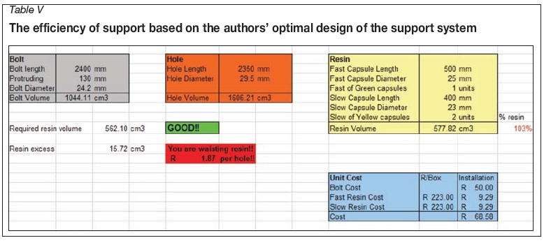
The authors' recommended support design is presented in Table V. The design will not only enhance safety at the mine but will also reduce the costs associated with mine support.
With such an optimal system, the mine can save costs by reducing the number of 500 χ 25 mm fast-setting resin capsules to one per hole while decreasing the size of the two slow-setting resin capsules to 400 χ 23 mm. The system is still efficient in terms of support, with 3% excess resin resulting in a waste of R1.84 per hole. The 3% excess will come in handy where there are geological discontinuities and the resin may seep into the discontinuities.
Underground observations
The following observations were made during the PTOs.
Insertion of resin capsules into the support holes
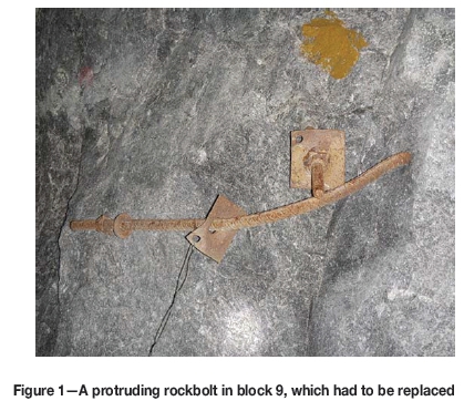
The mine uses the dual (slow/fast resin) system. With this system, it is critical to ensure that the resin capsules are inserted into the holes in the correct sequence. The fast-setting resin should always be inserted first, followed by the slow-setting resin capsules. Barrett (2006) stated that the idea behind this is to ensure that the fast-setting resin sets quickly in order to anchor the rock bolt firmly in the support hole, while the slow-setting resin sets later to lock in the tension in the rockbolt to create an active support. In all the underground observations, the authors noted that the correct number of resin capsules was used for each hole as per design. However, during the observations at the conveyor decline in block 9 and the top access in block 12, the authors ascertained that the resin capsules were not inserted in the correct sequence. The main errors included alternating the resin capsules and inserting the slow-setting resin capsules first. Inserting the fast-setting resin last results in rockbolts protruding by more than the maximum allowable length of 300 mm. Figure 1 shows a rockbolt that protruded as a result of incorrect sequencing of resin capsules into the support hole.
Orientation ofsupport holes
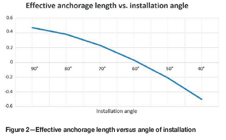
The orientation of the rockbolt during installation is crucial since it determines the bearing capacity of the bolt (van der Merwe, 1998). According to the mine's code of practice, the support holes must be drilled at an angle of not less than 70°, with a preferred installation angle of 90°. A rockbolt installed at an angle of less than 70° does not effectively clamp the 1.5 m fallout height of the hangingwall properly. Figure 2 shows how the effective anchorage length decreases with decreasing installation angle. It was observed that some of the support holes were not drilled at the preferred angle of 90° to the hangingwall and the sidewalls. This results in a decrease in the bearing capacity of the rockbolt and reduces the efficiency of the bolt in creating a stable beam. Such behaviour was observed in four of the six drill rig operators that were studied.
Length of support holes
The majority of the support holes were not drilled to the design length of 2.4 m, but were either over-drilled or under-drilled. The authors randomly selected and measured 12 support holes during installations in block 9, and 12 in block 12. The random selection of holes eliminates human bias and allows statistical conclusions to be made and generalized to a larger population. Figure 3 shows the deviation of the support holes from the designed length of 2.4 m both in block 9 and block 12.
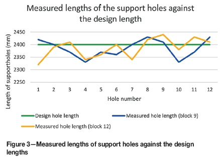
Only 12.5% of the support holes that were measured were drilled to the correct design length-37.5% of the holes were over-drilled while 50% were under-drilled. Under-drilled holes were mainly as a result of poor drilling practice or poor scaling of the excavation. Over-drilled holes were also a result of operator inefficiencies.
Importance of tensioning support holes
It is important to tension rockbolts properly, especially in shallow mining environments. In shallow mining environments there is no stress fracturing or horizontal clamping force to keep the rock mass together to create a selfsupporting hangingwall beam, as there is in deep mines (Gamboa and Atrens, 2003). The rock mass in shallow environments is in a tensile state and associated with weak joint planes or dilations in the hangingwall (Gamboa and Atrens, 2003). This is why it is important to effectively tension the rockbolts in order to create the required clamping force. The drilling of the support has an effect on the tension applied in the rockbolts.
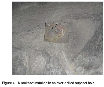
Over-drilled support holes
Over-drilling the support holes results in insufficient tensioning of the rockbolts. When a support hole is over-drilled, there may be insufficient thread left outside the support hole to fasten and tighten the nut (Barrett, 2006). Correct fastening and tightening of the nut results in effective tensioning of the bolt. Other impacts of over-drilling the support hole include the possibility (based on the degree of over-drilling) that some of the resins capsules may not be penetrated (Barrett, 2006). Figure 4 shows a rockbolt that was installed in an over-drilled hole.
Under-drilled support holes
When support holes are under-drilled, a significant portion of the bolt protrudes outside the hole. In this case, fastening and tightening of the bolt may result in either over-tensioning or under-tensioning. Figure 5 shows the difference between an over-tensioned and an under-tensioned rockbolt as a result of under-drilling the support hole.
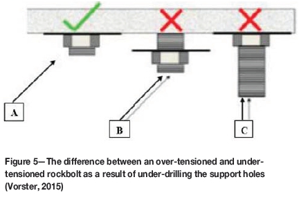
Under-tensioning occurs when the nut is fastened to the correct point, but due to under-drilling of the hole, there is a gap between the washer and the collar of the hole (B in Figure 5). Over-tensioning occurs when the nut is fastened beyond the threaded part of the rockbolt (C in Figure 5). Furthermore, when a hole is under-drilled the design bolt horizon may not be reached (Barrett, 2006).
Installation times (spin time and hold time)
Spin time is the amount of time taken to completely mix the mastic and catalyst by rotating the rockbolt during installation (Hagan, 2003). Hold time is the amount of time required after spinning before the rockbolt can be tensioned by the operator (Barrett, 2006). The spin time and hold time of the rockbolts at the mine, as per recommendations of the manufacturer of resin capsules, are 15 seconds and 45 seconds respectively. The spin and hold times were recorded during the formal and informal PTOs. The deviations of the measured spin times from the recommended spin time of 15 seconds are shown in Figure 6.
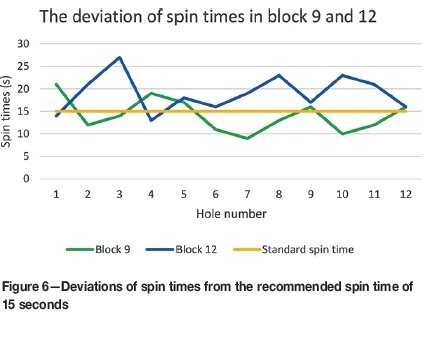
The deviations of the spin times were observed to be a result of operator inefficiencies. Under-spinning the rockbolt (37.5% of the installations) results in inadequate mixing of the two components of the resin capsule. The fast-setting resins are designed to start setting after 15 seconds. Over-spinning the rockbolt (62.5% of the installations) disturbs the gelation process of the fast-setting resin.
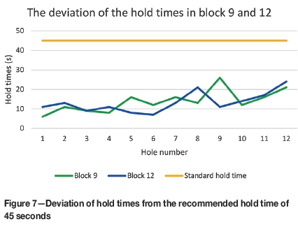
The deviations of the measured hold times from the recommended 45 seconds are shown in Figure 7. The results shown in Figure 7 indicate that all the rockbolts in the recorded holes were held for less than the required 45 seconds. This results in the rockbolts being prematurely tensioned. The deviations in both blocks were as a result of operator incompetency.
Economic benefits of the investigation
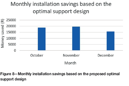
With the standard mine support design, the Andre Se Resin calculation indicated that the mine is wasting resin and losing R12.61 per support hole. The optimal design recommended by the authors will provide the mine with an efficient support system with a loss of only R1.84 per support hole, thus saving R10.77 per hole. This is a huge reduction in cost considering that the design is still efficient and is providing full security. A total of 5021 rockbolts were installed in the last quarter of 2015 (Table I). With a cost reduction of R10.77 per support hole, the mine could have saved R54 076.17, sufficient for the installation of 29 389 rockbolts.
Figure 8 shows the total amount that could have been saved per month based on Table I and the reduction of R10.77 per support hole as a result of the optimal design.
Furthermore, addressing the design and operational inefficiencies will also result in a decrease in the number of rockbolts that are installed incorrectly at the mine. The costs associated with the replacement of incorrectly installed resin-grouted rockbolts will thus be reduced significantly.
Practical significance of the study to the mining industry
The ability to create efficient support systems will help the entire mining industry to maintain the downward trend of fatalities as a result of falls of ground (Hermanus, 2007). This study will assist the mining industry's progress towards zero harm. The safety of mineworkers should be viewed not only as a moral obligation, but also as an instrument to enhance productivity. An efficient support system will result in enhanced safety, and commensurate with this, enhanced productivity and profits. With the current global state of economic affairs, improved productivity is essential for any mining company.
Conclusions
The investigation indicated that the standard support design used at the studied mine requires improvement. In practice the support holes are short of resin, leading to the rockbolts not being fully grouted. Drilling accuracy is a serious concern at the mine. Of the 24 holes that were measured, only 12.5% were drilled to the correct length. The rockbolts installed in the under-drilled holes (representing 50% of the measured holes) are either over-tensioned or under-tensioned, while those installed in over-drilled holes (37.5% of the measured holes) are definitely under-tensioned. The mine is faced with considerable challenges when it comes to conforming to the installation time recommendations. The majority (62.5%) of the rockbolts were over-spun and the remaining 37.5% were under-spun. All the bolts in the 24 representative holes were under-held.
The incorrect order of insertion of resin capsules into support holes and poor orientation of the holes calls for enhanced training and supervision of the support crew. Decreasing the design diameter of the support hole from 32 mm to 28 mm, supplemented by a decrease in design length from 2.4 m to 2.35 m, results in an optimal support design and a reduction of the money wasted per support hole from R12.61 to R1.84.
The following measures are recommended.
► The standard mine support design should be optimized by reducing the diameter of the drill bit from 32 mm to 28 mm and reducing the length of the support hole from 2.4 m to 2.35 m. These changes will enable the mine to use different combinations of resin capsules to reduce the cost of installation per support hole
► The mine should provide intensive training to the support crews to address the concerns associated with drilling accuracy and conformity to the rockbolt manufacturer's recommendations
► Informal and formal planned task observations should be carried out more frequently by the rock engineering department to ensure adherence to set standards
► The use of a T-spanner to re-tension all the installed rockbolts is recommended, since the results presented indicate that all the rockbolts were under-held and tensioned prematurely
► It is important to test the quality of the resins by sacrificing one resin capsule from each box before using the contents underground. Operators are urged to break the resin capsule sheath and mix the two components by hand, measure the time it takes for the resin to set and verify if it is within the manufacturer's specifications. This will indicate whether the surface or the underground conditions have affected the resins.
References
Barrett, P. 2006. The Minova Guide to Resin-Grouted Rock Bolts. 1st edn. Book Production Consultants, Cambridge. [ Links ]
Barton, N., Lien, R., and Lunde, J. 1974. Engineering classification of rock masses for the design of tunnel support. Journal of Rock Mechanics and Geotechnical Engineering, vol. 6, no. 4. pp. 189-236. [ Links ]
Cawthorn, R.G. 2007. The centenary of the discovery of platinum in the Bushveld Complex. Journal of the Southern African Institute of Mining and Metallurgy, vol. 107, no. 1. pp. 1-4. [ Links ]
Chen, D. 1994. Design of rock bolting systems for underground excavations PhD thesis, university of Wollongong. [ Links ]
Esterhuizen, A. 2014. Unique fall-of-ground prevention strategy implemented at Two Rivers Platinum Mine. Journal of the Southern African Institute of Mining and Metallurgy, vol. 114, no. 10. pp. 785-790. [ Links ]
Ferreira, P.H. 2012. A perspective on underground support technologies in Southern African platinum mines to reduce safety risks and enhance productivity. Proceedings of the 5th International Platinum Conference: ' A Catalystfor Change', Sun City, South Africa, 17-21 September 2012. Southern African Institute of Mining and Metallurgy, Johannesburg. pp. 445-482. [ Links ]
Gamboa, E. and Atrens, A. 2003. Environmental influence on the stress corrosion cracking of rock bolts. Engineering Failure Analysis, vol. 10, no. 5. pp. 521-558. [ Links ]
Hagan, P.C. 2003. The effect of resin annulus on anchorage performance of fully encapsulated rockbolts. Proceedings of the 10th Congress of the International Society of Rock Mechanics: 'Technology Roadmap for Rock Mechanics', Sandton, South Africa. International Society for Rock Mechanics. pp. 113-118. [ Links ]
Henning, P. and Ferreira, P. 2010. In-stope bolting for a safer working environment. Journal of the Southern African Institute of Mining and Metallurgy, vol. 110, no. 1. pp. 47-51. [ Links ]
Hermanus, M.A. 2007. Occupational health and safety in mining-status, new developments, and concerns. Journal of the Southern African Institute of Mining and Metallurgy, vol. 107, no. 8. pp. 535-540. [ Links ]
Mark, C. 2000. Design of roof bolt systems. Publication no: 2000-151. National Institute for Occupational Health and Safety, Pittsburgh, PA. [ Links ]
Tadolini, S.C. 1998. The effects of reduced annulus in roof bolting performance. Proceedings of the 17th International Conference on Ground Control in Mining. Department of Mining Engineering College of Engineering and Mineral Resources. West Virginia University, Morgantown, WV. pp. 230-236. [ Links ]
Van der Merwe, J.N. 1998. Practical Coal Mining Strata Control: a Guide for Mine Managers and Supervisors at all Levels. 2nd edn. ITASCA Book Distribution, Johannesburg. [ Links ]
Varden, R. and Villaescusa, E. 2006. A methodology for selection of resin- grouted bolts. Proceedings of the US Symposium on Rock Mechanics (USRM), Golden, Colorado. American Rock Mechanics Association. pp. 1-7. [ Links ]
Vorster, C. 2015. Mandatory Code of Practice to combat rockfalls and rock burst accidents. Unpublished document. [ Links ]
Paper received Jan. 2017
Paper written on project work carried out in partial fulfilment of BSC Honours (Mining Engineering) degree.

