


Services on Demand
Article
 English (pdf)
 Article in xml format
 Article references
Indicators

Related links
-
 Cited by Google
 -
 Similars in Google
Share

 Permalink
Journal of the Southern African Institute of Mining and Metallurgy
On-line version ISSN 2411-9717
Print version ISSN 2225-6253
J. S. Afr. Inst. Min. Metall. vol.117 n.4 Johannesburg Apr. 2017
http://dx.doi.org/10.17159/2411-9717/2017/v117n4a2
STUDENT PAPERS
An investigation into the fragmentation of blasted rock at Gomes Sand
G.L. Gomes-Sebastiao; W.W. de Graaf
University of Pretoria
SYNOPSIS
Gomes Sand is a quarry operation that produces sand and aggregate for the construction industry. The quarry is experiencing inconsistencies in the fragmentation and poor pit conditions as a result of poor drilling and blasting practices. This results in excessive downtime in the load and haul and crushing processes.
A benchmarking exercise of the blasting practices was conducted to evaluate the effect of the inconsistency on the mining cycle. After changes in the blasting practices the downtime was reduced, which improved the crushing plant utilization by 4.9%. The improved blasting practices and more consistent fragmentation decreased the average number of loads lost each month due to jaw crusher blockages from 9.2% to 3.9% of plant throughput. The change in blasting practices also improved pit conditions.
Keywords: drilling, electronic delay detonators, blasting practices, fragmentation, communition, crusher throughput.
Introduction
Gomes Sand is a quarry operation that has been in operation since 2009, producing sand and stone for the construction industry. The quarry was experiencing unacceptable blasting results. The repercussions included uneven pit floors, large amounts of oversize rock (>500 mm), and inconsistent fragmentation.
The blast results affected the load and haul operations as well as the efficiency of the crusher. This resulted in downtime in the daily operations, and consequent production and revenue losses.
The crusher product should have a top size of 50 mm. A blast fragmentation of <50 mm would improve the downstream operations and the crusher throughput.
An investigation into the blasting practises was carried out to assess whether the downstream delays can be eliminated by improving the blast results. The exercise included:
► Assessing if the designed blast layout is adhered to on the bench
► Observing the quality and control of drilling
► Observing the charging procedure of the blast-holes
► Benchmarking the fragmentation consistency of the blasted rock using current blast design and practices
► Analysing the throughput of the crushing plant
► Investigating the power consumption of the crushing plant and determine if a change in blasting practices will affect this
► Evaluating the hours spent by the hydraulic hammer on secondary breaking.
Methodology
A number of site visits were made to determine whether the blast layout on the bench correlates with the designed layout. The burden and spacing of the blast-holes was measured against the design. The depth of the blast-holes was measured to determine if the blast-holes were being drilled to the correct elevation.
The following measurements were taken after implementation of the recommended changes in the blasting practices to determine the effect on fragmentation and overall blast performance:
► Fragmentation analysis of the blasted muckpile
► Throughput rate of the crushing plant by means of a time study
► Power consumption of the primary crusher, using the Bond Work Index and applying this to the blasted material.
Owing to time constraints, the results of previous blasting practices were based on data captured previously by Gomes Sand.
The hours spent by the hydraulic hammer on secondary breaking were evaluated and compared to the quantity of material blasted (in bank cubic metres). The lower this value, the less time the excavator would have spent removing oversize (>500 mm) from the muckpile. This will also be an indication of the probability of oversize blocking the primary crusher.
Background
In the mining and mineral beneficiation industry, size reduction of the as-mined material is necessary in order to recover the valuable minerals contained in the ore. In many mining operations blasting is the primary means of size reduction; if this can be done adequately it will have a major effect on the efficiencies of downstream processes. There are many factors in the blasting procedure that can be modified in order improve the blast result.
Blast-hole drilling
Drilling is the first step in the blasting cycle and can have the biggest influence on the cost of mining (University of Pretoria, 2014). Precise control needs to be exerted over the drilling practices, as this will have a major effect on the overall blast results. Blast-holes should not be under- or over-drilled, as this may result in hollows or toes developed in the bench below. This will cause uneven floors in the pit and affect the fragmentation of the collar zone when blasting the underlying bench (Chiappetta, 2014 ). According to Chiappetta, poor drilling practices account for 50% of issues causing unacceptable blast results.
Blast-holes are laid out on a bench in a sequential pattern in relation to the face of the bench. The hole can be drilled in either a square or a staggered pattern. A square pattern (Figure 1) will provide straight edges on the newly formed highwall. The pattern allows for easier drilling conditions as the drill rig moves in straight parallel lines. The shock wave from each blast-hole will overlap in between the rows but there will be less coverage in the centre of every group of four holes, as shown in the figure (AEL Mining Services, 2014).

Drilling the blast-holes in a staggered pattern (Figure 2) results in a better distribution of the explosive energy into the rock mass, which delivers better fragmentation. The pattern allows for better overlap of the shock waves from each blast-hole. The staggered pattern may result in stepped edges of the new highwall; to eliminate this, additional blast-holes may be needed. Drilling the holes in this pattern may present difficulties for the drilling rig to manoeuvre on the bench (AEL Mining Services, 2014).

The blast-holes can be drilled either vertically or at an angle. If the face that is to be blasted lies with a dip and the blast-holes are drilled vertically there will some variation in the burden. The hole might be moved closer to the crest of the bench to prevent the toes from being overburdened but this will mean that at the top of the blast-holes the burden will be too small. This will result in high levels of air-blast, noise, and flyrock (Xtract Training Services, 2015).
Drilling the holes at the inclination of the dip of the bench face will overcome the tough toe conditions. The burden will then have a more uniform distance throughout the blast-hole length. The inclined holes will result in a more effective use of the explosive energy. This gives improved fragmentation and reduces the amount of rock in the stemming region of the blast-hole, where boulders are often formed (Xtract Training Services, 2015).
Charging
Prior to charging, the blast-hole depth should be measured. This will establish whether the bottom of the hole is at the same elevation as when drilled (the column has not collapsed or the hole has not filled up with dirt) and how much explosive should be pumped into the blast-hole.
When pumping the bulk explosives into the blast-hole, consideration must be given as to whether the blast-hole is dry or contains water. Water ingressing into the blast-hole deposits a certain amount of slime, which accumulates at the bottom of the hole forming a column of mud. When charging a wet hole the charge lance must be pushed down the blast-hole to the bottom of the water, but not into the mud column. If the charging lance is pushed into the mud column this will cause contamination of the explosives with the mud and thus affect the performance of the explosives. Provided the explosive chosen is denser than water, such as emulsion or an emulsion blend, the explosives will displace the water.
This eliminates any pockets of water that can cause separation within the explosives column (Chiappetta, 2014).
Separation of the explosive in the blast-hole can still arise if the charging lance is pulled out of the blast-hole too quickly.
Stemming material
One of the most important aspects of the blast is the stemming design. Stemming is material such as drill chippings or aggregate that serves to block the explosives column and contain the blast energy within the blast-hole for a few extra milliseconds. This maintains the peak pressure in the rock mass for slightly longer; hence it will improve fragmentation and the heave of the muck pile (University of Pretoria, 2014). The correct stemming length will depend on the size of the blast-hole, the type of stemming material, and the rock mass properties. Reduction of the stemming length may improve the breakage of the rock in the collar zone of the blast-hole but will have an adverse effect on the overall fragmentation of the blast. This is because a shorter stemming length allows the explosive energy and gas to escape more easily, and thus it is not directed into the rock mass. A reduction in stemming length can cause more flyrock, noise, and air-blast.
The correct size for stemming material is considered to be 10-15% of the blast-hole diameter. The length of the stemming by rule of thumb is 20-30 times the hole diameter when using aggregate-due to the good interlocking properties of the aggregate-and 30-40 times the hole diameter when using drill chippings (University of Pretoria, 2014).
To maintain the peak pressure in the blast-hole and reduce stemming ejection, stemming plugs have been developed such as the Rocklock system. The use of such systems allows explosives to be loaded higher in the blast-hole, as the stemming length may be reduced. The stemming plugs help to reduce the risk of flyrock. The stemming plug is simply placed on top of the explosives and the stemming material on top of the plug. The plug also helps to prevent contamination of the stemming material with the explosives, which would have an effect on the blast performance.
The Rocklock plug is a plastic sphere that is partially filled with stemming material. Upon detonation the plastic flexes outwards and locks onto the sidewalls of the blast-hole. This creates a gas-impermeable layer that prevents the stemming from ejecting (Aggregates and Mining Today, 2010).
Initiation system
Pyrotechnic initiators
Until the turn of the century pyrotechnic delay detonators were a common choice to initiate the blasting sequences. With pyrotechnic delay detonators the timing sequence in which blast-holes can be detonated is fixed. Each down-line on the detonator has a specific time delay due to the speed of the burning front, and likewise with the detonator itself. Hence with pyrotechnic initiating systems there is very little opportunity to modify the timing of a blast initiation sequence.
The accuracy of the time delays is also unpredictable due to the inherent scatter of the timing, which can cause out-of-sequence firing. The scatter in the timing is caused by deviations in the intended timing delays. These deviations could lead to overlaps in the firing sequence of the detonators.
Figure 3 shows the firing sequence of three sequential timing delays in a three-hole blast. Plotting the nominal firing times of a detonator about the mean firing time produces a normal distribution curve for the detonators. The top graph shows the ideal firing sequence of the detonators, where they each fire individually. If the standard deviation deteriorates from the specified standard deviation, the curve grows wider and flattens as shown in the middle graph. There is an increased probability of the first detonator firing late and the second detonator firing early. The firing sequence of the detonators is still in the correct order but with little delay between each detonation. This phenomenon is termed 'crowding'. Crowding can reduce the throw of the muckpile, causing it to be tighter, and increase flyrock and ground vibrations.

If the standard deviation of the detonators firing times were to deteriorate further, there is a chance that detonator two would fire early, before detonator one and detonator one fire late (bottom graph). This overlap in the firing sequence can result in coarser fragmentation, increased flyrock, ground vibrations, and air-blast, and the production of toes.
Electronic delay detonators
The electronic delay detonator makes use of an electrical current to set off the detonation. The initiation system comprises blast box, a handheld tagger, two-core electrical trunk line, downline wires, and the electronic delay detonator.
The detonator consists of a microchip, a capacitor, a fuse head, and the explosives. The use of the microchip allows the tagger to assign each detonator a specific and independent firing time. When the detonator receives the programming signal, the capacitor stores the energy until the firing time. The capacitor then ignites the fuse head to detonate the explosives. This system eliminates the possibility of initiator lines being cut during the blast due to flyrock, as is commonly experienced with the pyrotechnic initiation system.
The detonators are designed to be intrinsically safe, since only a specific frequency and current sent from the blast box will fire a detonator (Hand, 2010).
Since each detonator is assigned a specific firing time there is a great deal of flexibility in the timing contours of the blast. Thus the correct timing contours and time delays can be designed to suit the geology and profile of a face. With the use of electronic delay detonators, blast results are now repeatable, unlike with pyrotechnic initiation. This advantage of the electronic delay detonators has conferred many additional benefits on the mining industry.
Electronic delay detonators have a scatter or timing error of only 0.01% of the programmed delay, compared with of up to 10% in pyrotechnic initiating systems (African Explosives Limited, Electric Initiating Systems). The scatter will result in a rough timing contour, which means there is not uniform fragmentation of the blast. Provided that all other blast parameters are correct, the use of electronic delay detonators will deliver a consistent fragmentation size. This improved fragmentation can result in better feed rates into the primary crusher, less oversize production and hence less secondary breaking required, and improved bucket fill factors and loading rates. By using the correct timing sequence for the specific block of ground to be blasted, the burden and spacing of the drill pattern can be increased. This means less drilling and explosives is needed for blasting the same volume of rock. Thus the system may offer an overall saving to the mine (Hand, 2010).
An added benefit of the unique timing sequences that can be set up with the system is single-hole firing, which can be practised in environment sensitive areas. Hence the mass of explosives detonated per delay can be controlled, and this in turn will reduce the ground and air vibrations.
Fragmentation
The law of conservation of energy states that energy can neither be created nor destroyed; it is simply converted into another form. By applying this law to the energy available in a blast-hole due to explosives; the more energy that can be channelled from the explosives into breaking the rock, the less is available to create air-blast and ground vibrations (Chiappetta, 2014).
In the production of rock for the purpose of aggregate manufacturing, one of the key aspects is to fragment the rock in manageable sizes that will minimize downstream processing costs. Hence when designing a blast, it is imperative to take the required fragmentation in the downstream processes into account.
Cunningham developed the Kuz-Ram empirical model in the 1980s to determine the mean fragmentation size of a blast.
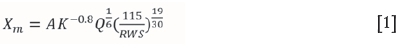
where
Xm= mean particle size, cm (50% passing)
A = rock factor (varying between 0.8 and 22, depending on hardness and structure)
K = powder factor kg/m3
Q = mass of explosive in the hole (kg) - above grade
RWS = weight strength relative to ANFO, 115 being the RWS of TNT (Cunningham, 2005).
When using empirical modelling to determine a blast's fragmentation, one must bear in mind the limitations of the process. The model states that an increase in energy will result in a finer fragmentation throughout the distribution of material. However, this may not be true in all real-life situations. Other factors that the model does not take into account are:
► Rock properties and structure
► Dimensions of the blast block
► Bench height and stemming relationship
► Timing and the accuracy of the timing
► Velocity of detonation of the explosives
► Whether decking is used in the blast-hole
► The condition of the sides of the blast block, which would have been affected by previous blasting (Cunningham, 2005).
Causes ofoversize
Oversize can be regarded as any fragmentation size produced by blasting that is too large for handling by the mine's standard equipment. It can also be regarded as material that requires secondary breaking before it can be handled. Different operations have different definitions of what constitutes oversize, since the requirements vary according to the site and equipment selection (Singh and Narendrula, 2010).
The optimal fragmentation size would be one that results in the best productivity and lowest costs when being loaded, hauled and processed. Oversize can have many implications for a mining operation such as:
► Time needed to remove oversize from the muckpile
► Inefficient loading operations
► Possible damage to load and haul operations
► More wear on load and haul equipment
► Increased wear and tear and jamming of crushers
► Secondary breaking costs (Singh and Narendrula, 2010)
Oversize may occur for several reasons:
Geological causes:
► Oversize generated due to a blocky seam that runs through the bench
► Oversize from conglomerate boulders that are embedded in the rock mass
► Joint and structural discontinuities that allow blast gases to escape.
Drilling practices:
► Deviations in the blast-holes will cause the burden and spacing to change. This will ultimately change the intended blast design
► Uneven burden and spacing will produce oversize.
Blast design and practice:
► Blast-holes must be charged correctly and with the correct charge mass per hole
► The blast-holes must be initiated in the correct sequence
► A misfire can lead to oversize being produced.
Sources of oversize in a bench:
► Collar zone-there is no explosive in this region of the blast-hole, as it is filled with stemming material. For this reason fragmentation can be limited
► Free face-an uneven face burden produced when rows from the previous blast did not blast correctly.
► Toe and sub-grade zone -
• Blast-holes are drilled to the incorrect depth
• The charge of the explosive mass at the bottom of the blast-hole is incorrect, causes a reduction of available energy. (Singh and Narendrula, 2010).
Effects of blasting on crushing and energy consumption
When processing blasted rock the effects of blasting on the fragmentation must be considered. The first aspect that must be considered is the more commonly understood size distribution of the blasted fragments. Fragment size plays an important role in the crushing and grinding processes. Coarse material will reduce a crusher's throughput and cause downtime due to blockages. The size distribution of the feed material to the primary crusher will affect the overall plant efficiency. Poor feed material may increase the load on the secondary crushers, as there may be less fines that can bypass the crushing circuit (Workman and Eloranta, 2013).
The next effect of blasting that must be considered is crack development in the blasted fragments. During the blasting process macro- and microfractures develop in the rock mass. Microfractures develop around mineral grains. The development of microfractures 'softens' the material, allowing it to break more easily. This is also beneficial to production, and reduces energy consumption and wear (Workman and Eloranta, 2013).
Due to the above factors, consideration must be given to how the product of the blast will affect processing. To determine the crushing and grinding efficiencies of blasted material two factors must be investigated, one being plant production and the other the energy consumption of the crushing and grinding equipment (Workman and Eloranta, 2013).
A theory of communition was developed by Bond in 1952. The theory provides a basis to estimate the energy required to reduce an 80% passing feed size to an 80% passing product size.
The equation developed by Bond is as follows:
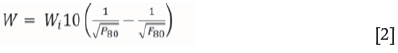
where
W = power consumed per ton (kW/t)
Wi = the Bond work index (kWh/t)
P80= the screen size at which 80% of the product will pass through (μ m)
F80= the screen size at which 80% of the feed will pass through μm)
(Gupta and Yan, 2006)
The energy consumed in the crushing process can be changed in several ways:
► Reduce the size of the material fed into the crusher by blasting. Less energy will be needed to crush the material to the same product size
► Reduce the Bond Work Index (Wi) through the generation of macro- and microfractures during blasting
► Increase the amount of fines which can bypass the crushing circuit, thus decreasing the amount of material that needs to be crushed.
All of the above three parameters can be changed during the stages of drilling and blasting (Workman and Eloranta, 2013).
Results
Original blasting practices
The blasts were originally designed using the following parameters:
Bench height 6.5 m
Hole diameter 89 mm
Stemming length 2.2 m
Stemming material 9.5 mm aggregate
Charge length (above grade) 4.3 m
Powder factor (theoretical) 1.2 kg/m3
Burden:spacing ratio 1:1.15
Burden 1.8 m
Spacing 2 m
Sub-drill 0.4 m
Initiator type Shocktube detonators
Burden delay timing 42 ms
Spacing delay timing 17 ms
Drill pattern Staggered
Hole angle 90°
Explosive properties:
Explosive type Emulsion - not blended
Relative effective energy (at 20 Mpa) 77
Water resistance Excellent
Charge mass per metre (Mc) 6.53 kg/m
Explosives in hole density 1.05 g/cm3
Booster size 150 g
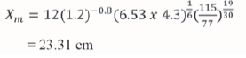
Kuz-Ram fragmentation prediction:
Blasting practices on the bench
It was found that there was very little control being executed over the implementation of the desired blast design. The intended drill pattern was not adhered too. The burden and spacing of the blast-holes were not consistent with the design. This resulted in irregular blast-hole spacings and the blast-holes not being in parallel rows.
The intended drill depth was determined using a staff and a dumpy level. Each blast-hole was assigned an individual drilling depth to ensure that an even floor would be created. Measurements showed that the blast-holes were not being drilled to the indicated depth. Blast-holes were being over-and under drilled.
No measurements were taken during charging of the blast-holes with the bulk emulsion. The charge lance was pushed to the bottom of the blast-hole to ensure that any water in the blast-hole was displaced by the emulsion. In order to pump the emulsion to the required height in the blast-hole, and thus ensure that the correct stemming length was obtained, a marker was placed 2.2 m from the end of the charge lance. The charge lance was pulled out of the blast-hole until the mark was reached, then pumping of the bulk emulsion was stopped. By doing this the correct stemming length was not obtained. Once the emulsion had gassed and the density decreased to the critical density, it would rise in the blast-hole, thus reducing the stemming length.
Blast product
It was found that the blasting practices produced large amounts of oversize rock (>500 mm). This necessitated the full-time use of a hydraulic hammer to carry out secondary breaking before the material could be processed.
Image-based fragmentation analysis was used to produce a particle size distribution of the muckpile, which can be seen in Figure 4. It must be noted that before the analysis was done, the majority of the oversize had already been removed from the muckpile. It can be seen that the blast product product was 80% passing 300 mm and contained 10% oversize.

New blasting practices
After consultation with mine management, the blast design parameters were changed as follows:
Bench height 13 m
Hole diameter 89 mm
Stemming length 2 m
Stemming material 9.5 mm aggregate and a 74
mm RockLock ball
Charge length (above grade) 11 m
Powder factor (theoretical) 0.9 kg/m3
Burden:spacing ratio 1:1.15
Burden 2.5 m
Spacing 2.5 m
Sub-drill 0.5 m
Initiator type Electronic delay detonators
Burden delay timing 32 ms
Spacing delay timing 12 ms
Drill pattern Staggered
Hole angle 90°
It was also decided to change the explosive type. The new explosive had the following properties:
Explosive type Emulsion - not blended
Relative effective energy (at 20 Mpa) 75
Water resistance Excellent
Charge mass per meter (Mc) 6.53 kg/m
Explosives in hole density 1.05 g/cm3
Booster size 400 g
Kuz-Ram fragmentation prediction:

Blasting practices on the bench
It was decided on recommendation to blast out every second bench in the pit, thus eliminating the 6.5 m high benches and creating benches of approximately 13 m high. Precise control was carried out over the drilling operation to ensure that the blast-holes were drilled parallel to one another and that the burden and spacing design parameters were adhered to.
Blast product
It was immediately observed after the first blast with a 13 m high bench and the new blasting practices that less oversize rock was produced along with a more consistent fragmentation.
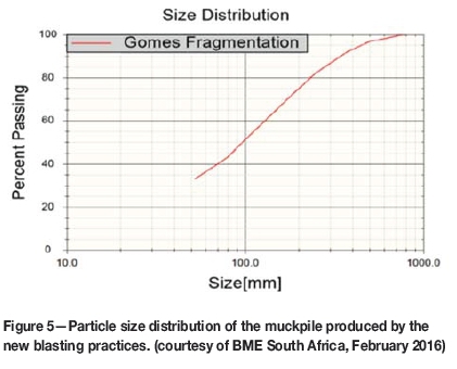
Image-based fragmentation analysis was again used to analyse the blast results. The oversize rocks had not been removed from the muckpile prior to this analysis. From Figure 5 it can be seen that the blast product was 80% < 237 mm and contained less than 3% oversize.
Analysis ofresults
After the new blast practices were implemented, a comparative study was conducted on the product of each blasting practice. The results from the month of August 2015, when the new blasting practices were implemented, were excluded since corrective measures were being done in the pit (blasting out toes) that resulted in a large amount of oversize being produced.
Effects of blasted product on crushing plant utilization
The crushing plant utilization increased from an average 91.5% when using the old blast practices to 96.3% with the new blast practices. When calculating the crushing plant's utilization, only downtime due to jaw crusher blockages (as a result of oversize entering the jaw crusher) was taken into account-all other downtime was excluded. The improvement in crushing plant utilization can be seen in Figure 6.

The increase in crushing plant utilization resulted from a decrease in jaw crusher blockages. Due to the decrease in jaw crusher blockages, the number of loads lost each month also decreased, as can be seen in Figure 7. The average number of loads lost each month decreased from 9.2% to 3.9% of plant throughput after changing the blasting practices. The throughput of the plant also increased by 15 t/h.

During September 2015 and February and March 2016, the material that was loaded and processed was from 6.5 m high benches that were blasted. As stated previously, the 6.5 m high benches were blasted out to develop 13 m high benches. When blasting the 6.5 m high benches the only blasting parameter that changed was the blast-hole depth. From Figure 7 it is evident that during these months there was an increase in the loads lost due to jaw crusher blockages in comparison to the other months during which the new blasting practices were used but 13 m high benches were blasted.
Effects of blasted product onjaw crusher power consumption
A working work index was calculated using the Bond Work Index theory, as the theory was modelling a crusher that was already in operation. It must be borne in mind that the theory does not account for any losses associated with crushing. The work index value for the rock mass at Gomes Sand was determined to be 11.2 ± 2.6 kWh/t (courtesy of Sandvik). To apply the Bond Work Index theory, the 80% feed size passing (F80) and 80% product size passing (P80) in Table I are required. These values were obtained through the mass balance conducted.

Working work index for new blasting practices:

Working work index for original blasting practices:

It is clear from the above two calculations that the working work index of the material decreased with the material resulting from the new blasting practices.
Hydraulic hammer usage
To quantify the use of the hydraulic hammer for secondary breaking of the oversize, only two blasts were analysed due to the paucity of available data. The evaluation was done by comparing the hours spent doing secondary breaking.
From Table II it is clear that there was a reduction in the time spent breaking oversize. This indicates that there is less probability of oversize being fed to the jaw crusher and blocking it. The reduction in oversize produced also reduces the time spent by the shovel removing oversize from the muckpile.

Conclusions
The evaluation of the blasting practices at the mine indicated that there was room for improvement. The implementation of new blasting practices resulted in an all-round improvement in the mine's operation and a reduction in downtime.
After placing more control over the drilling practices and the desired elevation of the blast-holes, the quality of the blasted floors in the pit has improved considerably. The correct and uniform spacing of the blast-holes allows for the correct and even distribution of explosives within the rock mass. This has helped to reduce the amount of oversize produced.
The increase in the bench height to 13 m high benches resulted in the production of less oversize rock along with a more consistent fragmentation, and the plant experienced less downtime due to jaw crusher blockages. The crushing plant's production also improved-loads lost each month due to jaw crusher blockages decreased, thus increasing the crushing plant utilization by 4.9%.
From the fragmentation analysis conducted it is evident that the new blasting practices produce a finer and more consistent sized muckpile compared to the original blasting practices.
Acknowledgments
The authors would like to acknowledge the following people for their contribution to this work.
Mr. W. Roux, from the Metallurgical Engineering Department at the University of Pretoria for his help with conducting mass balances on the jaw crusher.
Mr. P. Nell, from Demwreck Blast for his mentoring and making information freely available in order to conduct the exercise.
BME South Africa, for making the fragmentation analysis on the blasted muckpiles possible.
Thirushnee Padayachee (Fragmentation Analyst), for conducting the fragmentation analysis.
Mr. C. van Zyl, for his swift service and contribution towards the fragmentation analysis.
References
AEL Mining Services. 2014. Surface blasting handbook. Johannesburg. pp.16, 21, 31-32. [ Links ]
Aggregates and Mining Today. 2010. RockLock Stemming Plug now manufactured in the USA. http://a.aggregatesandminingtoday.com/rocklock-stemming-plug-now-manufactured-in-the-usa,2011-2,1485,0,0,featured-story.aspx [Accessed 29 October 2015]. [ Links ]
Chiappetta, R. 2014a. Optimizing your drill and blast strategy. Proceedings of Drill and Blast2014, Brisbane, Queensland, Australia, 29 April-1 May. International Quality & Productivity Centre, Sydney. [ Links ]
Chiappetta, R. (2014b). Practical methods for achieving better fragmentation with unique blast design concepts. Proceedings of Drill and Blast 2014, Brisbane, Queensland, Australia, 29 April-1 May. International Quality & Productivity Centre, Sydney. [ Links ]
Cunningham, C. 2005. The Kuz-Ram fragmentation model - 20 years on. https://miningandblasting.files.wordpress.com/2009/09/the-kuz-ram-fragmentation-model-e28093-20-years-on.pdf [ Links ]
GUPTA, A. and YAN, D. 2006. Mineral Processing Design and Operation. Elsevier, Amsterdam. [ Links ]
Hand, M. 2010. Electronic detonator systems. Proceedings of the Drilling and Blasting School, Misty Hills, Gauteng, South Africa, 19 February 2010. Southern African Institute of Mining and Metallurgy, Johannesburg. pp.39-64. [ Links ]
University of Pretoria. 2014. Course notes: Explosives Engineering 321. Department of Mining Engineering, University of Pretoria, pp.3-21. [ Links ]
Singh, S. and Narendrula, R. 2010. Causes, implications and control of oversize during blasting. Proceedings of the 9th International Symposium on Rock Fragmentation by Blasting (Fragblast 9), Granada, Spain, September 2009. Sanchidrian, J.A. (ed.). CRC Press, Boca Raton, FL. pp. 311-314. [ Links ]
Workman, L. and Eloranta, J. 2013. The effects of blasting on crushing and grinding efficiency and energy consumption. http://www.elorantaassoc.com/download/Papers/ESA_Effects_of_Blasting_ on_Crushing_and _Grinding_Efficiency_and_Energy_Consumption.pdf [Accessed 1 May 2016]. [ Links ]
Xtract Training Services 2015. Blasting Practices, Johannesburg. Chapter A5, C3. [ Links ] ♦
Paper received Jan. 2017
Paper written on project work carried out in partial fulfilment of B.Eng. (Mining Engineering) degree

