


Services on Demand
Article
 English (pdf)
 Article in xml format
 Article references
Indicators

Related links
-
 Cited by Google
 -
 Similars in Google
Share

 Permalink
Journal of the Southern African Institute of Mining and Metallurgy
On-line version ISSN 2411-9717
Print version ISSN 2225-6253
J. S. Afr. Inst. Min. Metall. vol.117 n.3 Johannesburg Mar. 2017
http://dx.doi.org/10.17159/2411-9717/2017/v117n3a8
GENERAL PAPERS
Narrow-reef mechanized mining layout at Anglo American Platinum
F. Fourie; P. Valicek; G. Krafft; J. Sevenoaks
Anglo American Platinum. Cyest Analytics
SYNOPSIS
Anglo American Platinum (AAP) is constantly striving towards safe, sustainable, productive, and cost-effective operations. There are many different initiatives, one of which is mechanization, and in particular, mining with extra-low profile (XLP) or ultra-low profile (ULP) equipment in pre-developed stoping areas.
This paper considers the best practices that have already been implemented within AAP's mechanized mining operations and details new-generation XLP and ULP equipment that is anticipated to be able to achieve monthly production rates in excess of 4000 m2, inclusive of the panel and advanced strike drive areas. The new-generation XLP equipment has completed its production trial and the ULP equipment is entering its proof-of-concept phase.
This paper will discuss the results obtained during the XLP production trial as well as the progress that has been made on the ULP equipment. Emphasis is placed on the higher production levels and greater efficiencies that can be achieved using this equipment. The paper will highlight the importance of the mining cycle as well as the availability of the equipment. It will also examine the new skills sets that will be required in the industry.
Keywords: mechanization, narrow-reef layout, extra-low profile, ultra-low profile, mining cycle
Introduction
Anglo American Platinum (AAP) is constantly striving towards safe, sustainable, productive and cost-effective operations. There are many different initiatives, among which mechanization, and in particular, mining with ultra-low profile (ULP) and extra-low profile (XLP) equipment in pre-developed stoping areas has been identified.
This paper considers the best practices that have already been implemented in AAP's mechanized mining operations and details the new-generation XLP and ULP equipment that is currently in the production trial and proof-of-concept phases respectively. This equipment is able to achieve a monthly production rate in excess of 4000 m2, inclusive of the panel and advanced strike drive (ASD) areas, when operating in the narrow-reef mechanized mining layout that was developed by AAP.
Emphasis is placed on the higher production levels and greater efficiencies that can be achieved using this equipment. The paper also highlights the importance of the mining cycle as well as the availability of the equipment. It examines the new skills sets that are required within the industry, and will discuss some of the interim results that have been achieved during the production trials and proof-of-concept trials.
The paper builds on initial analysis and modelling work that was conducted to understand and optimize AAP's existing XLP sections. The learning outcomes were then applied in the development of the ULP equipment.
The extensive modelling exercises demonstrated that improved safety and value can be achieved. The layout and technology discussed in this paper are currently being implemented in test sections at AAP. This paper is an expanded and updated version of the paper presented at the Sixth International Platinum Conference in 2014, and includes the results of the XLP production trial.
Purpose of the mine design
The mine design provides the parameters to be used in the layout of a new logistical mining method. The design criteria will be as practical as possible, and will endeavour to conform with and improve upon existing standards and best mining practices. The stoping method that will be used is an on-reef scattered breast mining system, utilizing ULP mining equipment that has been designed to operate in stoping widths of 0.90-1.20 m. It is important to note that the same mining method can be conducted using XLP mining equipment, which is operating in stoping widths ranging from 1.30-1.70 m.
This paper serves as a guideline to the ULP mining method; however, a 'fit-for-purpose' study must be conducted for each mine and circumstance prior to implementing the method.
Objectives of the new mine design
The introduction of the latest generation ULP and XLP equipment is expected to present the following opportunities.
► Safe operations through the reduction of personnel in the high-risk zone of the stopes
► Separation of machines and personnel through the use of remotely operated machines
► Creation of focused mining on primary development from the production stoping, thus having dedicated teams on development and stoping
► Primary development ahead of the stoping activity. This enables:
► Better understanding of the geology in advance
► Ability to install tipping points ahead of stoping, creating 'immediate stoping reserves', thereby enhancing flexibility and reducing production risk
► Improved productivity by having adequate faces available and reduction in re-development to establish faces through the adoption of a scattered breast mining system
► Low capital requirement due to recovering revenue from on-reef development
► Layout allows flexibility between stope sections, thereby enabling better resource sharing and scheduling
► Optimizing of the long-term ratio of machine makeup of the fleet in relation to the production outputs
► Creation of a flexible mining layout, allowing rapid response to market pressures
► Low stoping widths, resulting in higher head feed grades
► High-productivity stopes, resulting in high square metres mined per employee.
Mining method
The mining method is based on the concept that on-reef development takes place on the strike, prior to stoping, thereby ensuring that all the necessary services and infrastructure are in place prior to stoping. This results in an improvement in the overall efficiency of the section and will assist in providing a better understanding of the geology, which in turn will help to ensure better planning for the section before stoping commences. The stoping method that will be used is an on-reef scattered breast mining system, which will utilize ULP equipment that has been designed to operate in stoping widths of 0.90-1.20 m. The method that is described in this paper is based on a reef dipping up to 10°, although initial testing suggests that angles up to 16° can be explored.
The mining method described is suitable for both the UG2 and Merensky orebodies within the abovementioned range. As this is an on-reef mining method, the more uniform the ground conditions and the more limited the reef rolling conditions the better. On steeper dipping reefs, apparent-dip tramming roadways are required.
AAP's existing operations currently operate in reef dip angles ranging between zero and 30° with various ranges in depth. Where applicable, the on-reef pre-development layout outlined in Figure 1 provides an opportunity to choose the stoping technology that is most suited to the specific operations requirements. For the purpose of this paper, we will focus on a scattered breast mining method utilizing ULP equipment. However, it is important to emphasize that the mining method can change based on the operation's stoping width, mine depth, and angle of reef dip, resulting in condition-based mine design criteria (Figure 2).
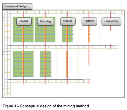
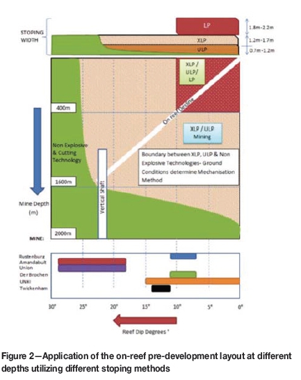
Table I gives a high-level summary of the various mechanized mining technologies that can be used for stoping.
Narrow-reef mechanized mining layout
The mine layout is based on a pre-developed seven-panel strike section that is mined from either side of each raiseline (scattered breast mining) and is capable of producing >4000 m2 per strike.
Twenty years ago, underground hard-rock mining traditionally made use of conventional mining methods. As the technology used in open pit mining evolved, the knowledge gained was applied to develop underground hardrock mechanized mining equipment. This resulted in the introduction of low-profile (LP) equipment into AAP's shallow operations (shallow operations are defined as operations up to 400 m in depth with a dip less than 10°), and subsequently in the development of the first generation of XLP equipment. The LP equipment was used for bord and pillar mining, and over the course of the past 15 years there have been significant improvements in both production and safety, with the average monthly production per crew currently being approximately 2400 m2.
Due to the historically high capital costs of the XLP equipment, as well as the inconsistent results (one month of high production followed by low production the next month) due to inefficiencies (from a logistical and geological perspective) in the traditional breast mining layout, the profit margins of an XLP operation were minimal compared to LP operations.
However, through the introduction of the latest generation XLP and ULP technologies as well as a clearer understanding of mechanized mining principles that was garnered through extensive analysis and modelling, XLP and ULP mining below 400 m utilizing the narrow-reef mechanized mining layout has been shown to create significantly more value from both a financial and an operational perspective, due to the extraction ratios that can be achieved using these methods coupled with the overall efficiencies (>4000 m2 production per month) of the XLP/ULP equipment.
The focus has therefore been on:
► The change management required to introduce the new XLP and ULP technologies
► Training in mechanization best practices through dedicated training centres
► Introduction of the narrow-reef mechanized mining layout.
Figure 2 provides a high-level overview of the various applications of the narrow-reef mechanized mining layout using various stoping methods. At present, significant work is being conducted within AAP in partnership with Anglo American in developing non-explosive technologies.
The layout consists of three main elements:
► On-reef pre-development
► Ledging
► Stoping (scattered breast mining).
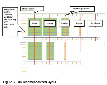
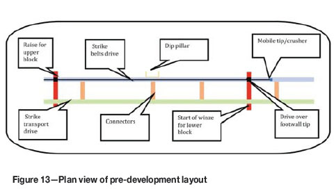
The on-reef pre-development is separate from the stoping activity, which forms an integral part of the stoping layout. The mining layout is designed around the principle of having four active raiselines (development, ledging, stoping, sweeping and vamping) as illustrated in Figure 3. To assist with the rapid development a mobile crushing unit has been developed.
Introduction to the XLP and ULP mechanized mining equipment
The mine design makes extensive use of mechanized mining equipment for on-reef pre-development as well as for the scattered breast mining stoping method. This section provides a brief introduction to the XLP/ULP mining cycle and equipment. The XLP equipment has been available within the industry for a number of years, and therefore greater emphasis is placed on the ULP equipment.
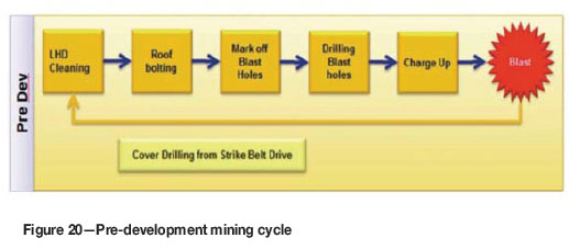
XLP/ULP mining cycle
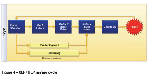
An overview of the mining cycle is given in Figure 4. It is important to note that the XLP/ULP equipment will be used to mine the panels and create the ventilation holings, whereas the low-profile (LP) mechanized equipment will be required to develop the advance strike drives (ASDs) and sidings.
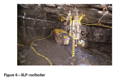
XLP equipment
In 2003 AAP partnered with Atlas Copco, Dok-ing, and Sandvik to develop equipment that was capable of operating in stoping widths ranging between 1.2-1.4 m (Figures 5 and 6).
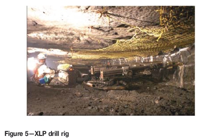
In 2007 the first XLP test trial was conducted at Amandebult mine. The equipment was later moved to Bathopele mine, where >3000 m2 has been achieved in a production section using the traditional (single-sided) XLP breast mining method.
ULP equipment
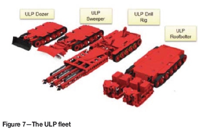
In 2003 the first XLP dozer was trialled at AAP. Following this trial, the need to develop a mechanized suite of equipment that would be able to operate in low stoping widths (<1.2 m) was identified. In 2007 a suitable original equipment manufacturer (OEM) was appointed and in 2011 an agreement was signed by AAP to develop the first ULP fleet.
The ULP technology is currently capable of operating in stoping widths ranging between 0.9-1.2 m at depths ranging from 350-1800 m at dip angles of up to 22°. The equipment has been designed to operate in fairly consistent orebodies. Figure 7 shows the ULP fleet
Key milestones in the progression of the ULP technology are:
► Full understanding of mechanization principles
► Modelling and optimization (mining cycle) of XLP and LP mining methods
► Development of a new on-reef mechanized layout (incorporating optimal face length and number of panels).
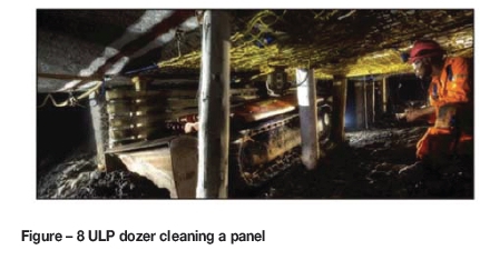
ULP dozer
The ULP dozer is designed to clean mined material from underground places of work and remove it into the ASD. Figure 8 illustrates the ULP dozer cleaning the panel.
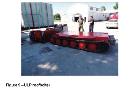
ULP roofbolter
The ULP roofbolter (Figure 9) is a double-boomed roofbolter that has been designed to operate in stoping widths between 0.9-1.2 m at a nominal bolting speed of less than eight minutes between collaring of successive 1.6 m holes.
ULPdrillrig
The ULP drill rig (Figure 10) is a three-boomed drill rig that has been designed to operate in stoping widths between 0.9-1.2 m.
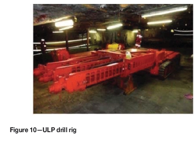
KPIs:
► The drill rig has been designed to drill a minimum of two panels in a five-hour working shift
► Power for the drill rig movement and positioning is provided by an onboard electric battery.
Depending on the deployed drilling technology and if technically possible, the same battery should be used as a source of energy for drilling. If this is not possible, an electro-hydraulic drilling system shall be deployed. In that case, this system shall be powered by the mine power grid
ULP sweeper
The ULP sweeper (Figure 11) is a cleaning tool intended to facilitate sweeping tasks in locations that the ULP dozer cannot reach. These sweeping tasks are currently performed manually.
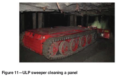
KPIs:
The mobile sweeper shall clean the following locations:
► The footwall of the stope between the face and the first line of support
► The accumulated remnant broken rock between the support structures of the first line of support
► The corner where the rock face and the footwall meet.
The unit is thus intended to sweep 10 m behind the face position. The sweeper has been designed to remove remnant rock in the work area.
Mining layout
Main access design
The orebody will be accessed via a barrel decline cluster as illustrated in Figure 12 (for the purpose of this paper, a three-barrel decline cluster has been used). The decline consists of a centre main dip conveyor decline and two transport declines, all of which are used for intake ventilation.

The dip of the three-barrel decline will be a maximum of 10° to accommodate trackless mobile equipment (TME). The spacing of the three-barrel decline cluster and regional and protection pillars will be in accordance with rock engineering requirements.
One of the transport declines will be a dedicated mine entry transport route and the other a dedicated mine exit transport drive. The drive under the belts will connect the decline transport system to the strike transport system.
Pre-development
The purpose of pre-development is to ensure that all the necessary services and infrastructure are in place prior to ledging or stoping taking place. The pre-development incorporates two strike drives, a raiseline, as well as pre-installed footwall (FW) tips. The layout has been designed to improve the overall efficiency as well as the logistics within the section. By pre-developing the strike before stoping takes place one is also able to gain a greater understanding of the geology, thereby improving the overall planning for the area.
The pre-development layout comprises the following design elements:
► Strike belt drives
► Strike transport drives
► Winze and raiselines
► Connectors
► Double-sided footwall tip.
The strike belt drive and transport drive are developed concurrently at intervals above and below the seven-panel mining area with a footwall tip situated in the strike belt drive on the top and bottom of each raiseline.
The strike belt drive is a designated drive for the belt and mine personnel, while the strike transport drive is a designated drive for machinery. The design makes use of connectors (interconnecting roadways) to facilitate movement between the strike belt drive and strike transport drive during pre-development. The interconnecting roadways ensure the tramming distances during the development of the strike belt, transport drive, and raiseline are kept to a minimum. This is achieved through the introduction of a mobile crushing unit fitted with a sacrificial belt, which is positioned in the strike belt drive.
A more detailed description of the footwall tip and mobile crushing unit is given in the section that follows; with the key design elements summarized in Table II.
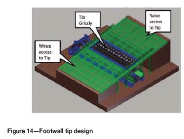
Footwall tip
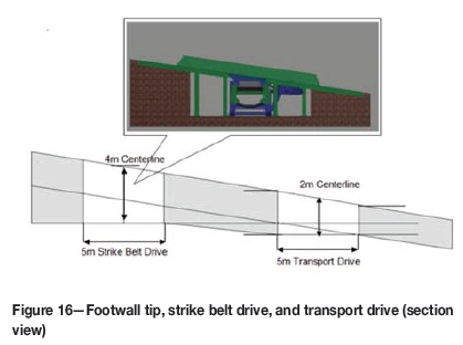
The double-sided footwall tip has been designed to establish flexibility between stope sections, thereby enabling better resource sharing. This is achieved by placing the tip in the footwall, thus making it accessible from either side of the raise. The tip has been designed to allow mechanized equipment to drive over the deck plates, allowing for quick and easy access into other stope sections. The tip has been designed to accommodate tipping by LHDs from both the updip and downdip sides of the raiseline. In order to reduce the tipping time as well as the need to go into the hangingwall, each LHD is fitted with a pushplate. Figures 14 to 16 illustrate the footwall tip and spoon feeder assemblies.
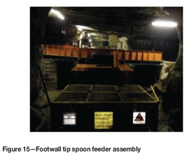
The spoon feeder has been designed to be applied in all AAP's underground operations. The design of the spoon feeder allows material from underground workings to be tipped onto the strike belt at a low trajectory angle by a vibrating or oscillating feed. The oscillating action of the spoon feeder controls the amount of ore that is deposited on the belt, ensuring that there will be no lumping and thus improving the lifespan of the belt.
The tip grizzly is designed to allow blasted rock smaller than 300 mm by 300 mm to pass through the tip into the spoon feeder (unless otherwise stipulated). The tip is equipped with a mobile pecker, which is able to break oversized rock into manageable pieces that will fit through the grizzly.
Figure 16 provides a cross-section of an installed footwall tip in the strike belt drive.
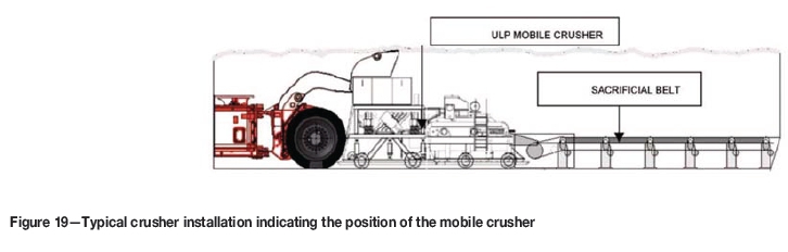
Mobile crusher
The mobile crusher (Figure 17) has been designed for underground mines, and will be installed in the centre of the strike belt drive. The crusher is intended to feed crushed material from development workings in a low-trajectory angle onto the strike belt. The mobile crusher has been designed to reduce the tramming distances of the LHD, thereby improving the overall development cleaning cycle. The mobile crusher is accessed from the transport drive via the interconnecting roadway as shown in Figure 18.
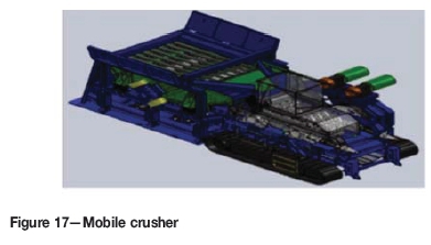
Figure 19 illustrates the LHD tipping onto the mobile crusher. The LHD should be fitted with a pushplate to reduce the tipping time.
Pre-development requirements
Pre-development will follow the mining cycle that is summarized in Figure 18. It is important to note that pre-development is done parallel with and independent of stoping.
The pre-development crew's role is to ensure that everything is in place for the stoping team to commence its work. Thus the crew will be responsible for the following:
► Development ends
► Cubbies
► Winzing and raising of the raiseline
► Satellite workshops
► Crosscuts (interconnecting roadways)
► Movement and installation of the tip and belts
► Reticulation extension
► Ventilation extension
► Vent holings (if required)
► Initial drainage.
Ledging
► On a true dip layout the stoping team will perform ledging. For ledging on apparent dip a separate ledging team will be required
► Ledging will proceed from the top to the bottom of the raiseline
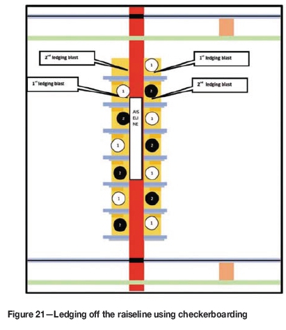
► Checkerboarding will be used for ledging to reduce long unsupported spans. The concept of checkerboarding is illustrated in Figure 21
► Off the raiseline, the ASDs and sidings will be blasted 6 m in (two blasts) using LP equipment
► At each alternative ledge face, a 1 m round followed by a 3 m round will be drilled by a LP drill rig positioned in the raiseline. This will be drilled to the required stope height between 0.9-1.2 m
► The blast will incorporate a ramp from the bottom ASD into the ledge so that the ULP equipment can access the ledge. This will predominately be throw-blasted into the ASD, the remainder will be cleaned with the ULP dozer
► The first 1 m of ledging will be supported using the LP bolter
► Once cleaned, the ledge will be supported using the ULP roofbolter (according to rock engineering specifications)
► From the third round onwards, the ULP equipment will be used to advance the ledge until the final primary support has been installed
► While the ledging is taking place the ASDs are kept at least 2 m, but not more than 10 m, ahead of the ledge using the LP equipment
► Permanent strike support is then installed along the raise according to rock mechanics standards
► Once the ledge is completed, then the ledge on the opposite side of the raise can be completed
► Once all ledging has been completed on either side of the raiseline, equipping can commence.
Stoping
The mining method that has been adopted for this layout is scattered breast mining utilizing ULP equipment with stope panels lagging the ASDs. Emulsion explosives will be used for charge-up and blasting.
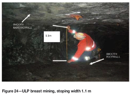
The stoping layout described in this paper is based on a mining depth of >500 m and therefore a siding has been incorporated into the layout. The stope face is to be drilled using at least a 2 m drill steel and advanced at the very least 1.8 m per blast while operating within stoping widths between 0.9-1.2 m (in this paper a stoping width of 1.1 m has been used).
The ASDs and sidings will advance at least 2.8 m per blast and should be drilled using a 3 m drill steel. Two 12hour shifts will be worked per day. Blasting is planned to take place on both shifts, although the layout offers an opportunity to create multi-blast conditions. Re-entry period will be as determined by the ventilation department. This results in an effective face time of eight hours and thirty minutes per shift.
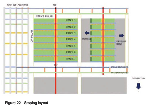
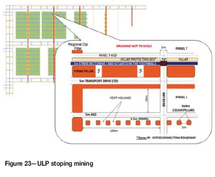
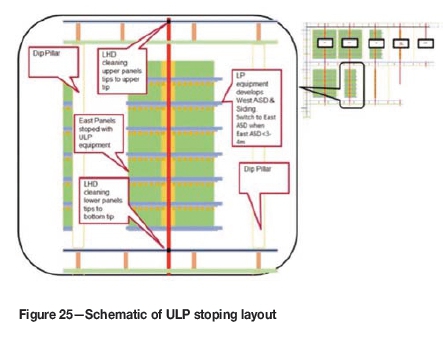
The stope panels and ventilation holings will be drilled using a ULP three-boom drill rig. A LP single-boom drill rig will be used to drill the ASD and siding. The ASD will be carried 2-10 m ahead of the stope. An overview of the stoping layout is given in Figure 22 and Figure 23.
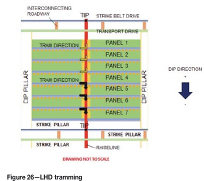
After the blast, the remaining ore that has not been throw-blasted into the ASD is dozed into the ASD from the stope panels using the ULP dozer. This ore is then trammed using the LHDs to either the updip or downdip footwall tips (refer to Figure 26).
During the first 30 minutes of stope face dozing the LHD must continue with other work so as not to interrupt the dozer cleaning the panel.
Stoping production outlines the anticipated production figures.
XLPI ULP mining cycle
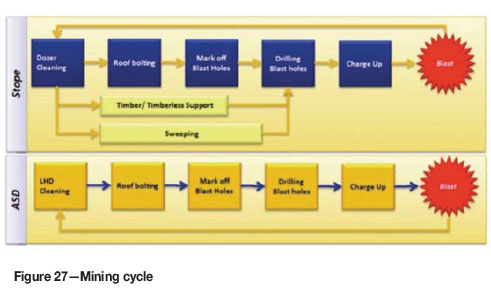
The mining method will follow the ULP mining cycle that is summarized in Figure 27. It is important to note that the pre-development is done in parallel to and independent of the stope and ASD development.
To blast 4000 m2, inclusive of the panel and ASD areas, 3.5 to 4 blasts per day (depending on the face configuration) are required for a two-shift cycle operating over 23 days per month. To achieve these blasts the resources available need to be scheduled to best fit within the seven-panel layout and mining logic. Consideration also needs to be given to the respective machines cycles and availabilities.
The general stope mining cycle is summarized in the ULP mining cycle depicted in Figure 27.
Some key sequencing concepts that were used to arrive at the monthly production figure of 4000 m2 are as follows:
> Panels 1 to 3 to be trammed to the upper tip, 5 to 7 trammed to the lower tip, and panel 4 can tram to either tip. This is done to reduce and optimize the average tramming distance
► Throw-blasting of 11 m is assumed in the stope panels due to:
►Breast stopes
- Electronic detonators
- Improved explosive technologies (emulsion explosives as well as tamping)
► The ASD needs to be of sufficient size so as to not choke the throw-blasted ore. The LHD needs to load the panel ore from the ASD for at least 2 hours to create sufficient space within the ASD for the dozer to doze the remaining ore into the ASD
► Note that in mechanized mining optimization, when a panel activity is complete, e.g. stope roofbolting needs to start at the next planned panel even if the activity will not be completed in the remainder of the shift. The object is to get as much work as possible done by the machines within the available face time. To optimize and control this scheduling, an intelligent management operating system (preferably a real-time system) is required to dispatch the machines and resources optimally. This should be managed from a control room.
Table III detail the cycle times for the cleaning, support, and drilling cycles. Existing LP and XLP equipment was modelled and a lost time factor was added to the total time based on underground time studies that had been conducted on both the LP and XLP equipment. This time includes time delays caused by changing drill bits, connecting water and power cabling to the machines, and other operational delays.
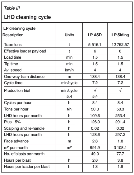
The design called for at least two 8 t LHDs to be used as optimization studies as well, as Arena modelling showed that the tons per hour reduces as the tram distance increases, which impacts the total tons that can be moved (Figure 28 and Figure 29).
The total face cycle time for both the LP and ULP equipment is a representative time that would apply to the total time it would take to support and drill panels 2 to 7, as these panels all carry a siding as well as vent holing. For the first panel, only the ASD and panel cycle times would be applicable as the first panel does not carry a siding or vent holing (Figure 22 and Figure 23).
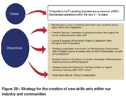
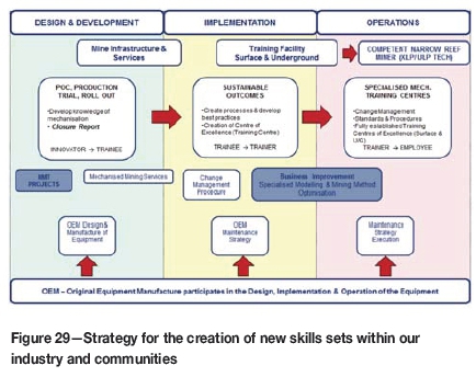
Training and development of new skills
Training, as well as the development of new skill sets, has been identified as a vital component for the implementation of mechanization in the mining industry.
The results thus far achieved from the XLP production trial clearly demonstrate that higher production levels (>4000 m2 per month) and greater efficiencies can be achieved with the new-generation equipment that has been developed. However, in order to maximize this potential, new skill sets (Figures 28 and 29) are required to be developed within the industry.
Operators of the future will need to be:
► Strongly focused on safety
► Goal-orientated
► Adaptable and flexible
► Able to think and act strategically
► Effective communicators
► Have a strong sense of teamwork and collaboration
► Visual spatial thinkers
► Capable of performing maintenance on their machines.
In order to create these skills for the future AAP has embarked on the creation of Centres of Excellence as well as experiential learning. Coupled to this, AAP is constantly looking at other innovative and creative ways to identify and garner these skills within the surrounding communities as well as applying best-practice measures taken from our peers in industry.
Conclusions and way forward
The following key milestones in the progression in narrow- reef mechanized mining have been met:
► Full understanding of mechanization principles
► Modelling and optimization (mining cycle) of XLP and LP mining methods
► Development of a new on-reef mechanized layout (incorporating optimal face length and number of panels).
The narrow-reef mechanized mining layout has been designed around (and focuses on) the following four key areas:
► Safety
► Sustainability
► Productivity
► Cost-effectiveness.
Safety
The mining layout is designed to remove personnel from the high-risk zone of the stopes.
► The ULP technology has been designed to separate machines and personnel through the use of remote- controlled technology
► The layout introduces a dedicated drive for machinery (strike transport drive) as well as a dedicated drive for personnel and belt system (strike belt drive)
► The layout allows for future automation of the mining process, which will be managed using a management operating system based in a control room on surface
► Through pre-development the orebody is better understood, resulting in better planning
►The layout requires a skilled workforce that is highly trained and highly safety-conscious
► The mechanized mining method improves underground conditions through the introduction of well-controlled hangingwall and sidewall conditions.
Sustainability, productivity, and cost-effectiveness
► The layout supports concentrated and dedicated mining within a section by divorcing the pre-development from the secondary development and stoping activities. The primary development team is responsible for ensuring that all the necessary services and infrastructure are in place before stoping commences within the section. The layout also offers the potential to switch between explosive (LP/XLP/ULP) and non-explosive stoping methods depending on the dip, depth, and resource width of the orebody
► Higher production levels and greater efficiencies can be achieved using mechanized equipment
► On-reef mechanization delivers early ounces (higher head grade). A majority of the capital and development costs are offset by revenue generated by on-reef development
► Flexible layout - the 14-panel layout has been designed to create flexibility within operations (the layout improves productivity by having adequate faces available and reduces the amount of re-development that is required to re-establish faces). The mining layout is designed around the principle of having four active raiselines (development, ledging, stoping, and sweeping and vamping)
► The layout incorporates logistical elements (optimal tramming distances, improved footwall conditions, tips, services, and IT infrastructure are in place prior to stoping)
► Pre-development results in upfront geological information
► The layout provides effective ventilation and support
► The ULP technology is able to operate in stoping widths of 0.9-1.2 m, thereby reducing the dilution and increasing the grade of the feed to the plant.
Through proper planning and the understanding of mining principles as well as the introduction of new technology, safer, more productive, and sustainable operations are possible in narrow-reef tabular mining systems.
References
Anglo American Platinum Limited. 2011. Building Foundations for the Future through Mining. Anglo American Integrated Report 2011. [ Links ]
Cambitsis, A. and Lane, G. 2012. A framework to simplify the management of throughput and constraints. Cyest Corp. Internal white paper [ Links ]
Valicek P., Fourie, F., Krafft, G., and Sevenoaks, J. 2012. Optimization of mechanized mining layout within Anglo American Platinum. Proceedings of the Fifth International Platinum Conference: A Catalystfor Change, Sun City, South Africa, 17-21 September 2012. Southern African Institute of Mining and Metallurgy, Johannesburg. pp. 1-34. [ Links ]
Fourie, F., Valicek, P., Krafft, G., and Sevenoaks, J. 2014. Narrow reef mechanized mining layout at Anglo American Platinum. Proceedngs of the 6th International Platinum Conference, 'Platinum-Metalfor the Future', Sun City, South Africa, 20-22 October 2014. Southern African Institute of Mining and Metallurgy, Johannesburg. pp. 1-20. [ Links ] ♦
Paper received Apr. 2016

