


Services on Demand
Article
 English (pdf)
 Article in xml format
 Article references
Indicators

Related links
-
 Cited by Google
 -
 Similars in Google
Share

 Permalink
Journal of the Southern African Institute of Mining and Metallurgy
On-line version ISSN 2411-9717
Print version ISSN 2225-6253
J. S. Afr. Inst. Min. Metall. vol.117 n.3 Johannesburg Mar. 2017
http://dx.doi.org/10.17159/2411-9717/2017/v117n3a5
NEW TECHNOLOGY PAPERS
Controlled foam injection: a new and innovative non-explosive rockbreaking technology
R.G.B. PickeringI; C. YoungII
IRod Pickering & Associates, Port Alfred, Eastern Cape, Cape Town, South Africa
IICFI Technologies, Steamboat Springs, Colorado
SYNOPSIS
Controlled foam injection, or CFI, is a highly effective, novel non-explosive rockbreaking technology that with appropriate implementation and application can replace traditional drilling and blasting methods with drilling and non-explosive breaking. The CFI technology is safer, more productive, environmentally friendly, and fully developed; and it can operate with the same flexibility as more traditional small-hole drilling and blasting. To date, CFI has been regarded as an interesting rockbreaking process that could be used only in a few specialized applications. However, in extensive trials it has successfully broken every rock type encountered and in reality it could be used in place of all mining and civil engineering rockbreaking processes that utilize explosives in short and small-diameter blast-holes. The narrow-reef hard-rock mines, typical of the southern African gold, platinum, and chrome sectors are under severe pressure to mechanize and preferably operate on a 24/7 basis, and this could be achieved through the application of CFI. What is still outstanding is a suitable machine to fit a defined application, such as tunnel development or stoping.
Keywords: non-explosive rockbreaking, controlled foam injection, mining cyble, continuous operatios.
Introduction
How do we increase productivity using technology as the driver for change? From studies in mining tunnelling it is obvious that developments in drilling technology, as well as increased drilling rates, have not led to a significant increase in the rate of tunnel development. Drilling rates with mechanized drills have increased fivefold in the last 50 years, while tunnel development rates in mechanized mining operations have reduced to about one-third of those 50 years ago.
The biggest obstacle to lower cost and safer mining in narrow-reef orebodies, typical of the gold, platinum, and chrome mines found in southern Africa, is the blasting cycle, with its inherent poor utilization of the mining assets. In conventional mining operations, the total face working time is typically less than eight hours per day and less than seven days a week. In reality only 25% of the totally available time is utilized to generate revenue (Fenn, 2016). What is required is a technology that allows for continuous mining, thereby maximizing the use of the asset. By implementing some form of non-explosive mining the rate of face advance can be increased and the length of face being worked can be reduced, which leads to more concentrated mining. Concentrated mining means less service infrastructure, less ventilation, and more effective management. In soft-rock mining this has been achieved with the introduction of pick-cutting machines, such as road-headers, shearers, and continuous miners. The introduction of pick-cutting in the coal mining industry in the 1950s led the move away from blasting and by the mid-1990s fatalities, measured in deaths per million tons produced, had reduced to only 1.6% of the 1947 figure and productivity at British Coal, measured in tons per employee, had risen by more than 20 times compared to the blasting era (Pickering, 2004). Replacing blasting with cutting also reduces the blast damage to the surrounding rock and increases safety. Operating 24/7 results in much higher rates of face advance in development ends, leading to shorter lead times to production and better NPV returns Thus, we see that the move to non-explosive mining had a major impact on safety, productivity, operating costs,, and return on invested capital.
The only rock-cutting machines that have been operated successfully in hard-rock mining are raise-boring machines and, in very limited applications, tunnel-boring machines (TBMs). All these machines use discs or buttons to break the rock, primarily in compression; and to overcome the high compressive strength of the rock requires very high forces, massive machines to supply these forces, high power, and consequently high capital cost. This is exacerbated by the high running cost of these machines due to the exceedingly high abrasivity of the rock. To make matters worse, these machines are difficult to manoeuvre, which makes following the reef very difficult, if not impossible, and furthermore they only cut circular openings.
Original equipment manufacturers (OEMs) have conducted extensive work, often funded by mining companies, to develop rock-cutting machines for hard-rock mining. Because of the inherent inefficiencies of cutting hard rock in compression, some OEMs have developed rock-cutting machines that attack the rock in an undercutting mode to break the rock in tension, as the tensile strength of these hard rocks is 5-10% of the compressive strength. Some examples are:
► The Mobile Tunnel Miner (MTM6), first developed by Wirth in the 1990s for HDRK and recently given a new lease of life by Rio Tinto when a new machine for tunnel development was commissioned (Tunnelling Journal, 2010). Within a few months of going underground in 2012 the project was cancelled. It is not known if this was due to technology challenges or a change in mine ownership (Delabio, 2015)
► The Sandvik MN220 Reef Miner, previously known as the ARM 1100, was first developed in 2001 and extensively developed over the next four years (Pickering et al., 2006). It recommenced trials in 2014. Despite achieving defined key performance indicators during both trial periods it still has not been implemented as a mining machine, and the required associated mining system is currently being optimized (Janicijevic and Valicek, 2015).
To date, no-one has been able to develop a hard-rock cutting machine for everyday commercial use in the mining industry, other than for the specialized application of raise-boring circular shafts and a few specialized TBM-driven mine access projects.
The above story is interesting and has been told many times to justify the introduction of new technology. However, the recent work carried out by the Chamber of Mines sheds a new light on the possible future of the gold and platinum mines in South Africa. This work was presented at the New Technology and Innovation in Mining Colloquium organised by the SAIMM and is part of the Mining Phakisa initiative.
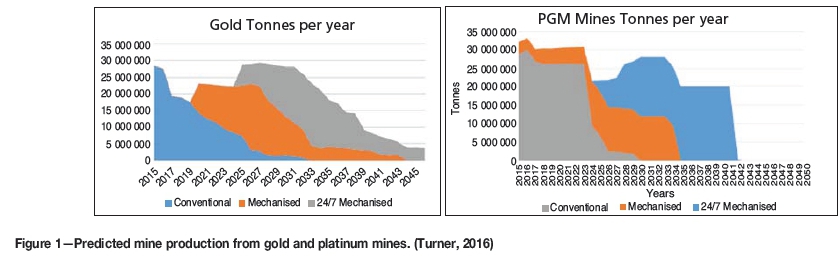
Figure 1 shows predicted production from the gold and platinum mines in South Africa. In each graph the block on the left is production from conventional mining and indicates the predicted closure of the gold and platinum mines by 2026; unless the mines mechanize. The central block indicates an increased lifespan if the mines are mechanized with drill-and-blast operations, and the block on the far right shows how the life of the mines could be extended until the middle of this century through the introduction of non-explosive mechanized mining operating 24/7. It has been stated that without this drive to modernize mining it will not be possible to unlock the potential to:
► Achieve zero harm and get closer to the goal of eliminating fatalities
► Mine South Africa's deep-level orebodies profitably. Consequently, without modernization, 200 000 jobs could be lost by 2030 (Macfarlane, 2016).
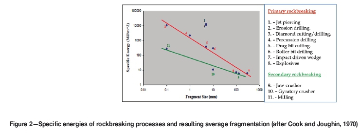
In today's environment of high energy costs, the energy efficiency of the rockbreaking process is also of paramount importance. The graphs in Figure 2 clearly show how the specific energy consumption per cubic metre of rock broken is directly proportional, on this log-log graph, to the fragmentation size produced by the rockbreaking process. The top line represents primary rockbreaking from a solid face, and the second line secondary rockbreaking associated with crushing and milling processes; two very different activities, best demonstrated by considering milling at 200 MJ/m3 and diamond drilling at 10 000 MJ/irr3 for the same particle size. With some of the more exotic rockbreaking processes proposed by researchers, such as the use of lasers, energy consumption is often ignored. It can be seen that with blasting the average fragmentation size is 100 mm and the specific energy about 6 MJ/m3, whereas in roller-bit drilling the average fragmentation size is 10 mm and the specific energy consumption 300 MJ/m3. With explosives, this energy comes from a chemical process, but in other rockbreaking processes this energy arrives at the face in the form of electrical energy. A typical example is the Wirth MTM6, which has an installed power of 1870 kW and was designed to drive a 5 m χ 5 m tunnel at a rate greater than 12 m/d.
What is really required for a continuous mining system is to eliminate the explosives, which generate fumes, dust, and violently break the rock; and instead use a simple flexible technology that relies on drilling a hole and breaking the rock in tension and that can be incorporated into a mining system that continuously removes the broken rock and installs appropriate support. Preferably, all this should be delivered with reasonable energy consumption.
Controlled foam injection
Controlled foam injection (CFI) is based on extensive research that has been funded by governments, mining companies, and OEMs. CFI breaks the rock in tension by pressurizing the bottom of a drilled hole with foam. Typical operating pressures of the foam are less than 50 MPa, as it exploits the tensile strength of rock, which is much lower than the compressive strength. The successful features of CFI are the development of a cheap and easily installed seal at the bottom of the hole and the use of foam as the pressurizing fluid. The foam is chemically inert and environmentally safe; with one exception, all the components of the foam are used in commercial food products. If water alone were used then, after the rock fractures and the pressurized volume increases, the water pressure would drop dramatically, as water at these pressures is substantially incompressible. The rock would be fractured but not liberated and removed from the breaking zone. If gas alone was the driving force, then the stored energy in the gas would propagate the fractures and violently displace the broken rock. CFI has the ability to pressurize a controlled fracture (or system of fractures) in such a manner that the pressures required to adequately propagate the fractures (without over-pressurizing them) can be maintained and it is possible to break the rock, propagate the fractures, and liberate the rock in a controlled fashion.
Foam, which is a two-phase mixture of liquid and gas, can be made to have a viscosity several orders of magnitude higher than those of gas or water, thus foam enters into a developing fracture system much more slowly than gas or water. With a much slower penetration of the fracture system, the pressures required to initiate, extend, and develop the desired fractures are much lower than if a gas is used. The use of water alone is not sufficient because this relatively incompressible liquid rapidly loses pressure as the fracture volume increases with fracture growth. The fracturing process will usually proceed so rapidly that the needed fluid pressure in a water-based system cannot be maintained by injecting additional liquid down the injection tube or barrel. In contrast, foam can maintain the pressures for efficient fracturing, due to the expansion of the gaseous phase of the fluid. Foam thus has the ability to provide the pressures for efficient controlled fracturing without requiring the excessively high pressures associated with explosives, propellants, water cannons, or electrical discharge.
Foam suitable for fracturing hard competent materials by penetrating foam injection may be made from any combination of liquid and gas; the most obvious liquid and gas to use are water and air. The surface tension properties of water alone are such that water/air foam would rapidly separate into its two components. This separation may be slowed or almost eliminated by using any of numerous commercially available surfactant materials, such as conventional soaps and detergents, or specific surfactant compounds such as lauryl sulphate (sodium dodecyl sulphate). The stability and viscosity of foam may be increased by adding a gel such as guar gum or hydroxyl-propyl guar. By varying the ratios of water, air, surfactant, and gel, foams with a very broad range of viscosities and stored energies can be manufactured. The foam may be generated externally to the actual controlled fracturing device in a conventional high-pressure reservoir using a variety of mixing and blending means.
The general features of a CFI device for rock excavation or concrete demolition are illustrated in Figure 3. The foam injection tube or barrel is inserted into a pre-drilled hole. The successful sealing of this tube into the hole, as indicated in Figure 3, is needed for the proper operation of the CFI process; this seal differentiates CFI from all the other propellant or water pressurization devices.
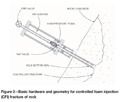
Once the device reservoir is charged with foam at the desired pressure, the foam is released into the pre-drilled hole by means of a rapid-acting reverse-firing poppet valve. A reverse-acting poppet (RAP) valve, as indicated in Figure 3 and illustrated in more detail in Figure 4, is attractive for controlling high-pressure foam injection because the valve has only one moving part, the poppet, which will open very rapidly when the pressure is dropped in the RAP control tube behind the poppet. As soon as the poppet moves, the reservoir foam pressure will act on the full sealing face of the poppet, causing it to retract or open quite rapidly. The high-pressure foam will then be rapidly delivered to the bottom of the hole and effect a controlled fracturing of the rock. Rapid opening is important so that the bottom of the pre-drilled hole may be brought to a high enough pressure rapidly enough to induce the desired combination of hole-bottom fracturing and radial fracturing needed to achieve complete fragmentation.
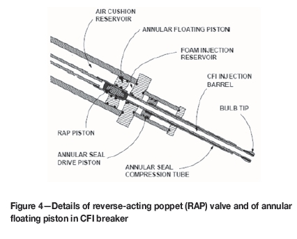
It is desirable to avoid injecting more foam than is needed to achieve the required fracturing. Excess foam injection represents a waste of energy and would result in some increase in the (albeit low) air blast and fly-rock associated with CFI fracturing. An effective means of controlling the amount of foam injected is by incorporating an annular floating piston into the foam reservoir as shown in Figure 4. This piston separates the rear portion of the reservoir, which need only contain a high-pressure air cushion, from the forward portion which contains the foam. The accumulator effect of this piston allows for the displacement and injection of a desired foam charge into the barrel and hole bottom without a significant drop in the accumulator pressure. This feature further increases the energy efficiency of the CFI rockbreaking process.
The sealing method for CFI fracture utilizes an injection tube with a bulb enlargement at its tip and an annular hydraulic piston acting around the smaller barrel of the tube, as illustrated in Figures 3 and 4. Sealing is effected by crushing an annulus of deformable material between the bulb tip and the annular piston. The crushing is effected with the annular sleeve on the CFI barrel driven by an annular piston. The crushing of this material along the axis of the hole causes it to expand radially and seal against the hole wall near the bottom of the hole. Application of high-pressure foam will cause the barrel and bulb tip to retract and further jam the material against the hole wall. With the proper selection of bulb tip angle and deformable material, the recoil will further jam the material against the hole wall and maintain a very effective seal. Any deformable material may be used, but granular materials such as sand, fine gravel, or a cementitious mix have been found to work well. Tests to date with a variety of cementitious materials have given excellent sealing, with negligible gas/foam leakage occurring around the barrel when breaking hard granite at pressures as high as 83 MPa.
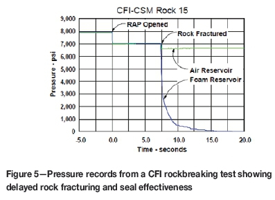
An example of the seal effectiveness is shown in Figure 5. The air reservoir trace is taken from behind the annular floating piston (see Figure 4), and the other trace is from the foam reservoir. The records in Figure 5 show the initial foam reservoir pressure of nearly 55 MPa (8 000 psi) prior to opening of the valve and the rapid drop of both pressures to 48 MPa (7 000 psi) as the hole is charged. As indicated in Figure 5, the 48 MPa foam pressure was not able to immediately fracture the rock and there was a 7.4 second delay before the rock fractured, with the seal holding firmly at this pressure. Once fracture was initiated the fracturing process was completed quite rapidly, with nearly 0.5 t of rock being excavated in a fraction of a second. Once fracture was initiated the foam pressure rapidly dropped to zero and the air-cushion pressure dropped 45 MPa.
There are other significant benefits derived from the unique viscous properties of foams. The viscosity of foam depends strongly upon foam quality, defined as the volume fraction of gas. Foams of gas volume fraction less than 50% typically have viscosities only slightly higher than that of the liquid phase. As the gas volume fraction increases from 50% up to about 90%, foam viscosity increases markedly and can be more than an order of magnitude higher than that of the liquid phase. As the foam gas volume fraction increases above 95%, the foam breaks down into a mist and the viscosity drops rapidly to approach that of the gas phase. In a CFI fracturing operation the foam might be generated initially with a gas volume fraction below 50%, albeit at very high pressure. As the foam expands into the developing fracture system, the gas volume fraction will increase with a concordant increase in viscosity until the foam has expanded to a 95% or greater quality. This variation of effective viscosity with expansion serves to improve the efficiency of the CFI process in two ways. While the higher pressure foam is being generated, delivered to the injection device, and injected via the barrel into the hole, viscosity will be low, as desired. Once the rock or concrete begins to fracture, the foam expands and viscosity increases, preventing the premature escape of the pressurizing medium before breakage is complete. Once breakage is complete the foam expands further, and as a gas volume fraction over 95% is realized, the viscosity drops, allowing the foam (now a gas mist) to escape more rapidly and thus reducing the time during which high-pressure foam can accelerate fragments of the broken material. By appropriate design of the foam, a sequence of viscous behaviours optimally tailored to the foam injection/material-breakage process can be achieved. This modification of foam properties is a simple process that can be carried out by the operator.
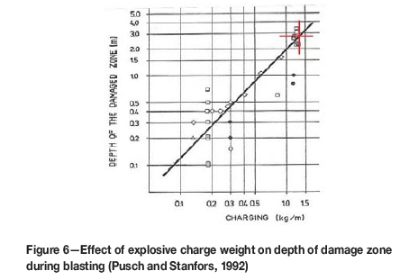
The rockbreaking characteristic of CFI dictate that the initial fracture is propagated from the bottom of the drilled hole at an angle of about 45° before curving around to the surface, as shown in Figure 2. This initial fracture breaks a slab of rock that is roughly three times greater in diameter than the depth of the hole. The structure of the rock dictates the final fragmentation. Further than the initial penetration of the fracture below the drilled hole there is no additional damage to the sidewall or hanging of the excavation. In blasting, the shock wave generated by the blast can cause extensive damage to the surrounding rock, and work by Pusch and Stanfors (1992) has shown that in a typical mechanized mining operation where the perimeter holes are drilled with a 43 mm bit and charged with pneumatically loaded ANFO, the depth of induced fracturing will be between 2.5 m and 3 m (Figure 6).
During fracturing by blasting, excessive dust is released from the zone of crushed rock around the blast-hole. Even when propellants are used to break the rock, and there is no zone of crushed rock, dust is generated during the rock fracturing process. No measurements of dust generated during the rockbreaking process using CFI have been made; however, after the break has been completed, the surface of the exposed rock of the primary fracture is covered in a smear of foam, and it is considered that this effectively reduces the amount of dust generated. Subsequent fracturing will generate dust from the fracture planes. When CFI is incorporated into a mining machine it may be necessary to introduce further dust alleviation methods such as flooding the breaking zone with a water mist, as in coal cutting.
Field tests with the 51 mm diameter device were carried out at the Colorado School of Mines (CSM) test mine located in Idaho Springs, Colorado. The rocks in this mine range from highly fractured gneiss to massive and competent schist and gneiss. Tests in the mine environment also allowed for the effects of developing face geometry and successive breakage interactions to be observed. For example, the influence of rock anisotropy and jointing upon breakage was evaluated. Similarly, the sensitivity of breakage to foam properties as controlled by surfactant, additives, and gas concentration was studied.
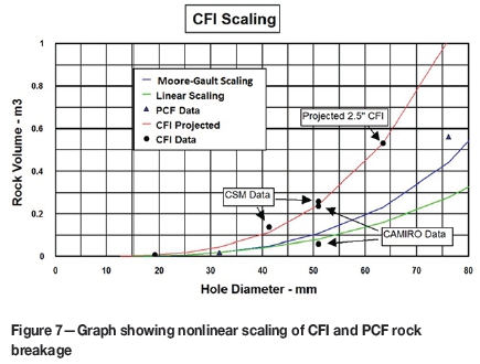
The tests conducted at the CSM experimental mine provided confirmation on scaling of the CFI process. Existing data on rock breakage by a variety of methods indicates that the efficiency of breakage improves with the scale of breakage. Thus, the energy required to excavate a unit volume of rock decreases with increasing scale of breakage. This effect is primarily due to the interaction of larger and weaker rock defects (fractures, joints, parting planes, etc.) with the process at larger scales. For propellant, gas-driven fracture the scale enhancement is approximately 50% for each doubling of the linear scale. That is, a doubling of the hole diameter and an equivalent increase in the device dimensions should yield eight times the material, but in reality it results in the breakage or removal of twelve times as much material. The data for CFI breakage in the CSM test mine, along with data for penetrating cone fracture (PCF) breakage in the same mine, is shown in Figure 7. Both PCF and CFI breakage follow a nonlinear scaling. This nonlinear scaling would be manifested both in a reduction in the pressure required to break rock, and in an increased breakage efficiency at larger scales.
During the course of efforts to evaluate the ability of the CFI method to break rock in the CSM mine, considerable experimental data on the process was obtained. This data served to both confirm the proper functioning of the prototype CFI equipment and to provide guidance for the measurements that might be utilized for process control in more commercial applications of the method. It was determined that control of the CFI process, including control of foam quality, could be achieved with simple measurements of gas pressure in the air-cushion reservoir, and foam pressures in the foam generator and subsequently the foam reservoir. Other aspects of a commercial CFI process, such as hole drilling, indexing for CFI injector placement, and hole-seal crushing, could all be monitored and controlled by existing hardware and techniques utilized in commercial automated machinery, including remote radio control.
The big question that still needs to be answered is what the mining rate will be in a specific application. To date it is estimated that the mining rate from one CFI breaking tool, in solid competent rock, will be between 3 m3/h and 6 m3/h.
This is based on past experience of the time to complete a cycle and experience in breaking from smaller drill-holes. The science based on Moore-Gault scaling and experience with PCF and CFI production suggests that with a 63 mm diameter drill-hole, CFI will break 0.5 m3 per event. To put this in perspective, with a typical 600 mm staggered drilling pattern used in gold mining stopes, with a stope width of 1.1 m and an advance of 0.9 m, each drill-hole produces 0.3 m3 of rock from the blast. Drilling intensity in platinum mines is higher due to the tougher rock conditions, and consequently production per drill-hole is even lower.
CFI has been extensively tested in a variety of different rock types and thus far all of the rock types have been successfully broken. The component parts required to compress the air and water and to generate and store the foam have been engineered and proven. Consequently, it is argued that the CFI technology is already developed - what is still lacking is a mining machine to accurately demonstrate the mining rate and operating cost in a specific application. The advantages of an integrated CFI mining machine will be a safer mining environment (as was demonstrated when coal mining moved from blasting to non-explosive excavation), low energy consumption, a relatively low capital cost combined with a low operating cost, and it will enable the mine to operate 24/7.
The exciting thing about CFI is that it can find application wherever small-diameter and short blast-holes have been used by the mining and construction industries. It can replace explosives in these applications and the mining and construction industries can have a genuine hard-rock, non-explosive rockbreaking tool. In southern Africa, a different machine could be designed and manufactured using CFI as the rockbreaking technology, and applied for tunnel development and stoping in the entire narrow-reef, hard-rock mining operations typical of the gold, platinum, and chrome mining sectors.
The following are some of the obvious applications for a tunnel development type of machine:
► In all mining, stoping, and development of narrow-reef tabular orebodies currently mined using a room-and-pillar layout and by mechanized trackless equipment. This is because in room and pillar mining the basic mining operation is tunnel development
► Globally, in all tunnel development for existing and new mines, whether they are mined conventionally or as mechanized operations.
With time, other specialized machines could be developed for:
►Narrow-reef stoping at flat and steep dips
► Narrow-vein mining practiced all over the world for a variety of minerals
► Breaking through dykes and rock too hard to mine with continuous miners in mechanized coal mining
► Secondary breaking in all cave and longhole open stoping operations.
Other applications could include the following:
► Many civil rockbreaking activities take place in built-up and congested environments. CFI could solve problems associated with noise, vibration, and fly-rock
► TBMs have found extensive application in civil rock excavation, but in hard rock it is often necessary to excavate rock not cut by the TBM, such as interconnections between two drives or the corners of a round TBM excavation. CFI could be used as it is a gentle rockbreaking process and the lack of violent fly-rock would minimize damage to other installed infrastructure in the already developed and equipped TBM drive.
Proposed project
How do we go about implementing this novel and developed rockbreaking technology in mining machines? CFI has been installed on eight different platforms; in all cases the primary concern was to develop and demonstrate the CFI technology. Machines have been tracked and wheel-mounted; the common denominator of these vehicles is that they have all used low amounts of power, with a rating of less than 60 kW. The disadvantage of these demonstration units is that none have been built for a specific underground application that takes advantage of the way CFI breaks the rock. The immediate requirement is to clearly demonstrate the rockbreaking rate and operating cost by building a rockbreaking machine based on CFI, which will be the basis for a mining machine designed to operate in a specific application such as tunnelling or stoping. In such a machine the various CFI parameters of pressure, hole size, and foam composition would be varied to determine the optimum rockbreaking performance in the defined application. At a later stage a mining machine that concurrently breaks the rock, removes the broken rock from the working face, and installs support would be designed and manufactured. At this stage it is considered that the application that should be focused on is tunnel development.
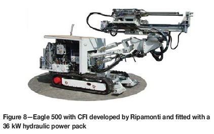
The machine that comes closest to meeting this requirement was developed by Ripamonti and used to break out safety niches when the Fréjus rail tunnel was recently enlarged and refurbished. This machine is shown in Figure 8.
Conclusion
Economic and societal pressures make it essential that the safety and productivity of the narrow-reef hard-rock mining industry improves. It is suggested that this can be achieved by replacing drilling and blasting with a novel non-explosive rockbreaking technology. The alternative technology is referred to as controlled foam injection (CFI). To date, CFI has been regarded as an interesting rockbreaking process for specialized operations; however, it can operate with the same flexibility and with higher productivity than more traditional small-hole drill-and-blast operations. Just as in blasting, where the explosive charge weight and composition are varied to achieve a specific performance, the CFI parameters of pressure, hole size, and foam composition can be varied to achieve different rockbreaking performance. Changes in CFI parameters are simple to make and as rock conditions in a tunnel change so CFI parameters can be adjusted. The major benefits of CFI can be summarized as follows:
► CFI is safer as it does virtually no damage to the rock surrounding the excavation due to the controlled manner in which the rock is fractured. The rockbreaking process is sufficiently gentle to allow workers in close proximity to mining. There have been no measurements of dust generated during a CFI event; however, on observing a rockbreaking event it can be seen that the newly fractured surface is covered in white foam. Experience with the change from blasting to non-explosive cutting demonstrated a massive improvement in safety in coal mining; CFI can have the same impact on narrow-reef hard-rock mining
► CFI is a very productive and efficient method of breaking rock as it generates more broken rock per metre drilled than conventional drilling and blasting. Over a ten-year period of experimentation CFI has successfully broken every rock type in which it has been tested. It is flexible in operation, with the CFI parameters easy to modify for different rock conditions. Installed machine power is low, and the specific energy of rock-breaking is very low when compared to hard-rock cutting. The installed power for the Wirth MTM6 is just under 2 MW; the power for a CFI machine would be more like 60-90 kW, as the stored energy in the foam is accumulated over a period of time. The fracture is generated from the bottom of the hole and thus maximizes the use of the drilled hole. The production of broken rock per metre drilled is higher than that in conventional drilling and blasting. A machine utilizing CFI will have to drill a hole and then break the rock, and it is envisaged that such a machine will be similar to a mechanized drill rig and consequently the capital cost of equipment should be similar to electro-hydraulic drill rigs. Additionally, because of the low power demand and low forces the equipment can be light and hence low cost in comparison to a MTM6 or TBM. Operating costs should also be similar to electro-hydraulic drill rigs, with the main costs being drilling consumables and general operation of the machine
► The CFI breaking process is environmentally friendly as it yields no fumes, no dust (except that released from existing rock fractures), very low noise levels, and very limited fly-rock, so people can work relatively close to the breaking process. The chemicals used in the foam are totally inert and thus environmentally safe
► The CFI technology is well developed, having been tried and tested for over 15 years. The hardware used to provide the high-pressure foam has proven to function reliably over long periods of service. The hardware for generating and delivering high-pressure foam to the bottom of the drilled hole has been proven in prototype rigs. The primary function of these rigs was to develop CFI and not to develop a mining machine. Finally, and very importantly, the sand seal is a very effective and very low-cost seal. This high-performance seal allows the injected foam to maintain the pressures to initiate and propagate the unique hole-bottom fracture.
CFI could be used in place of all mining and civil engineering rockbreaking processes where the rock is broken by explosives in short, small-diameter blast-holes. The narrow-reef, hard-rock mines typical of the southern African gold, platinum, and chrome sectors would then be able to operate continuously on a 24/7 basis. The next step will be to manufacture a narrow-reef mining machine for tunnel development or stoping and prove that this non-explosive rockbreaking technology can be integrated into a machine that will deliver safer and more productive mining operations.
References
Cook, N.G.W. and Joughin, N.C. 1970. Rock fragmentation by mechanical, chemical and thermal methods. Proceedings of the Sixth International Mining Congress, Madrid. [ Links ]
Delabbio. 2015. Personal communication. [ Links ]
Fenn, A.G. 2016. Unlocking value by reorganizing the operational value chain through modernization. Proceedings of the New Technology and Innovation in the Minerals Industry Colloquium. Emperors Palace, Johannesburg, 9-10 June 2016. Southern African Institute of Mining and Metallurgy, Johannesburg. pp. 35-50. [ Links ]
Janicijevic, D. and Valicek, P. 2015. A review of hard-rock cutting equipment technology development at Anglo American and Anglo Platinum. Proceedings of MPES 2015, Mine Planning and Equipment Selection 2015, 'Smart Innovation in Mining, Sandton Convention Centre, Johannesburg, South Africa. Southern Institute of Mining and Metallurgy, Johannesburg. pp. 455-468 [ Links ]
Macfarlane, A. 2016. Moving to next generation mining systems: a Chamber of Mines view. Proceedings of the New Technology and Innovation in the Minerals Industry Colloquium. Emperors Palace, Johannesburg, 9-10 June 2016. Southern African Institute of Mining and Metallurgy, Johannesburg. [ Links ]
Moore, H.J., Gault, D.E., and Heitowit, E.D. 1965. Change of effective target strength with increasing size of hypervelocity impact craters. Proceedings of the Seventh Hypervelocity Impact Symposium, Tampa, FL, February 1965. Vol. IV (Theory). Martin Co. [ Links ]
Pickering, R.G.B, Smit, A., and Moxham, K. 2006. Mining by cutting in narrow reefs. Proceedings of the International Platinum Conference - 'Platinum Surges Ahead', Sun City, South Africa, 8-12 October 2006. Symposium Series S45. Southern African Institute of Mining and Metallurgy, Johannesburg. pp. 221-230. [ Links ]
Pickering, R.G.B. 2004. The optimization of mining method and equipment. Proceedings of the First International Platinum Conference, 'Platinum Adding Value', Sun City, South Africa, 3-7 October 2004. Symposium Series S38. Southern African Institute of Mining and Metallurgy, Johannesburg. pp. 111-116. [ Links ]
Pusch, R. and Stanfors, R. 1992. The zone of disturbance around blasted tunnels at depth. International Journal of Rock Mechanics and Mining Science and Geomechanics Abstracts. vol. 29, no. 5. pp. 447-456. [ Links ]
Tunnelling Journal. 2011. www.tunnellingOurnal.com Dec 2010/Jan 2011 [ Links ]
Turner, P. 2016. Value creation through modernisation of South Africa's mining industry. Proceedings of the New Technology and Innovation in the Minerals Industry Colloquium. Emperors Palace, Johannesburg, 9-10 June 2016. Southern African Institute of Mining and Metallurgy, Johannesburg. [ Links ]
Young, C. 1999. Controlled-foam injection for hard rock excavation. Proceedings of the 37th US Rock Mechanics Symposium, Vail, CO, 6-9June 1999. American Rock Mechanics Association. [ Links ]
This paper was first presented at the New technology and innovation in the Minerals Industry Colloquium', 9-10 June 2016, Emperors Palace, Johannesburg, South Africa.

