


Serviços Personalizados
Artigo
 Inglês (pdf)
 Artigo em XML
 Referências do artigo
Indicadores

Links relacionados
-
 Citado por Google
 -
 Similares em Google
Compartilhar

 Permalink
Journal of the Southern African Institute of Mining and Metallurgy
versão On-line ISSN 2411-9717
versão impressa ISSN 2225-6253
J. S. Afr. Inst. Min. Metall. vol.117 no.2 Johannesburg Fev. 2017
http://dx.doi.org/10.17159/2411-9717/2017/v117n2a8
WITS SPECIAL EDITION - VOLUME II
Reflections on narrow-reef platinum mining pillar design systems as applied to a large platinum exploration feasibility project
T. ZvarivadzaI; J.N. van der MerweI, II
ISchool of Mining Engineering, University of the Witwatersrand, South Africa
IIStable Strata Consulting (Pty) Ltd, South Africa
SYNOPSIS
Platinum is a highly valuable resource, its safe and economic extraction is paramount. The success of platinum mining by the bord and pillar method depends heavily on a comprehensive and dependable pillar design method. Pillars need to be large enough to safely support the load and small enough to avoid loss of resources. A critical evaluation of current pillar design systems used in narrow-reef platinum mining was undertaken using practical experience from a large feasibility-stage platinum exploration project, supplemented by observations from several platinum mines in Zimbabwe. An extensive literature survey was undertaken in order to determine the current status of design systems. Through this approach, the shortcomings of current pillar design systems are highlighted. Areas are proposed for further research to obtain a better understanding on how additional factors influence pillar system stability. The exploration work highlighted how rock mass classification methods can be utilized in determining the overall strength of pillars. Current pillar design systems for narrow-reef platinum mining consider width-to-height-ratio (usually with different exponents for width and height) and the strength of the pillar material. However, there are many more important factors that are not considered and which have a bearing on pillar system stability. An in-depth study of these parameters with a view to establish effective narrow- reef platinum mining pillar design systems needs to be undertaken.
Keywords: pillar design, pre-feasibility, platinum mining, hard rock, comparative
Introduction
Pillars have been used as a means of support since the early days of mining. Pillar-supported mining methods such as bord and pillar require a reliable design system for them to be successful. This paper presents an evaluation of the current hard-rock mining pillar design systems as applied to a practical large-scale narrow-reef platinum mining feasibility study. It is vital to have a dependable pillar design system for economic and sustainable mining. Using an extensive database collected from the project, the pillar strength formulae were tested and several discrepancies noted. This necessitates the establishment of more reliable pillar design systems. In narrow-reef platinum mining, large compressive stresses accompanied by geological and geotechnical factors contribute to pillar instability. A well-formulated pillar design system is required that accounts for such factors so as to minimize pillar failures.
A pillar layout design system has to consider the hangingwall, the pillar material, and the footwall as all these three work together for the success of the system. Ozbay, Ryder, and Jager (1995) describe the hangingwall in shallow hard-rock mining situations as a rock mass containing well-defined discontinuities and subjected to deadweight compression. When the hangingwall is unsupported, it becomes susceptible to backbreaks if critical spans are exceeded (Ozbay, Ryder, and Jager, 1995).
Pillar design theory
Different pillars are used in narrow-reef platinum mining, depending on the function the pillar is to serve. In hard-rock tabular mining in general, a combination of pillar types is utilized. Dave (2009) classifies these types as shaft pillars, bracket pillars, boundary pillars, water barrier pillars, barrier pillars, crown pillars, sill pillars, strike-stabilizing pillars, dip-stabilizing pillars, non-yielding pillars, yielding pillars, and crush pillars. Salamon (1983) classified these pillars into three main types -support pillars, protective pillars, and control pillars. He explains that support pillars are usually laid out systematically to offer support to the undermined ground. According to this classification, protective pillars protect surface structures and underground mining excavations or separate one mine from its neighbour, while control pillars are those laid out systematically and cut in deep-level mines to curb rockbursts by reducing energy release rates.
Current pillar design systems are based on the empirical determination of pillar design parameters. This approach relies entirely on the failure of pillars for an empirical pillar design curve to be calibrated. It cannot be used for mines outside the empirical range that the pillar design is intended for. Several formulae are currently in use to determine pillar strength. For the calculation of load, the tributary area theory (TAT) which applies to regular mining layouts is used. Coates' (1981) method is also used to determine pillar load for large rectangular pillars like regional pillars. Parameters currently accounted for in the design of narrow reef platinum mining pillars are strength, load, width-to-height (w/h) ratio, and pillar foundation bearing capacity. The w/h ratio is generally used as a first indication of pillar strength. Martin and Maybee (2000) compared extensive data collected from back-analysis and concluded that most pillars fail at a w/h ratio of less than 1.5, while there is a substantial increase in pillar strength at a w/h ratio of more than 2. Stacey and Page (1986) mention that foundation failure, rather than pillar failure, can be expected at a w/h ratio of more than 7, provided that the pillar and foundation material are the same. Numerical modelling tools are also utilized to aid pillar design.
Pillar load determination
Tributary area theory
Pillar stresses are normally calculated using the tributary area theory (TAT), which accounts for the full cover load. This theory is used in regular mining layouts of large lateral extent (several times greater than the mining depth) and assumes that each pillar in the layout supports an equal load to the surface. This allocates full cover load to each pillar in the layout. Pillars of the same size must be used in the regular mining layout for the TAT to be applicable. This approach appears to be operationally convenient as it leads to fixed pillar-design dimensions for any given seam material and depth. The TAT assumes that a pillar carries the full load of the overburden above the pillar itself and halfway into the surrounding roadways (Salamon and Oravecz, 1976; Salamon and Munro, 1967; Hoek and Brown, 1980; Roberts et al., 2002).
The average pillar stress (APS) can be expressed as a function of extraction ratio as follows:
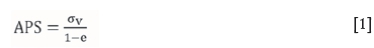
where σv is the vertical component of the virgin stress (MPa), e is the areal extraction ratio, ρ is rock density (kg/m3), g is gravitational acceleration (m/s2), h is depth below ground surface (m), and ov = pgh.
Hoek and Brown (1980) present an alternative formula for calculating APS for square pillars using the TAT. For a square pillar layout, the formula is:

where σv is the vertical component of the virgin stress, W0 is the excavation width (bord width), and Wp is the pillar width.
Coates' method
Coates (1981) presented his formula for load calculation after realizing that while the TAT can be utilized, it is insufficient since it does not consider geometrical and rock properties in its formulation. He went on to consider these parameters in the derivation of his formula. Coates (1981) admitted that his formula is only applicable in the centre of the mining area with undisturbed long rib pillars and in situations where the mine span does not exceed half the depth. Coates' formula (1981), which is applicable for calculating pillar load in deep and long mining zones, is given by:
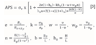
where σv is the vertical component of the virgin stress (MPa), e is the areal extraction ratio, H is height of the stope (m), σh is the horizontal component of the virgin stress (MPa), ν is Poisson's ratio for abutments, vp is Poisson's ratio for pillars, E is Young's modulus for abutments, Ep is Young's modulus for pillars, Bo is room width (m), Bp is pillar width (m), and L is width of extraction span (m).
It is evident that the formulation of Coates (1981) does not consider overburden stiffness and seam stiffness, factors that play a pivotal role in determining pillar load.
Note: Coates' method reduces to the usual TAT when L →∞ as shown in the calculation below.
When L →∞, Bp = 0, b = 0 and hs = 0 such that
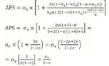
Coates (1981) mentions that his formula considers the following geometrical (layout) and rock characteristics: the span of the mining zone with respect to its depth, height of the pillars, pillar locations within the mining zone, horizontal stress, and modulus of deformation of the pillar and wall rock materials.
Theory of pillar strength determination
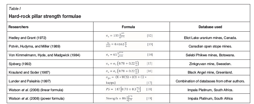
There are a number of issues that the current formulae used to determine hard-rock pillar strength do not address. Most of the strength formulae developed for hard-rock pillars have an empirical base. They were proposed after studies from different mines using failed pillar information. The formulae take the power form or linear form, but have a common aspect of considering the w/h ratio of the pillars under study. The forms of the pillar strength formulae are as given in Equations [4] and [5].


where
σsis the strength of a pillar with width w and height h K is the adjusted or non-adjusted strength of a unit cube of pillar rock determined statistically or through the use of laboratory results α, β, A, and B are constants.
There are several representative coal pillar strength formulae from which the currently used hard-rock pillar strength formulae were deduced. These are:
While there are a lot of factors to consider in calculating pillar strength, the rock mass strength of the pillar material and the shape and the size of the pillar are the three factors which several researchers, including Salamon and Munro (1967), Wagner (1980), Stacey and Page (1986), and Madden (1990) put forward as the factors on which the pillar strength depends. They mention that width and height, and gross structural features such as clay bands, faults, and joints are the parameters that define pillar shape and size.
Martin and Maybee (2000) propose that formulae developed empirically should not be used for w/h ratios of more than 2.
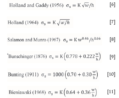
Hard-rock pillar strength formulae
Table I presents some strength formulae used in hard-rock pillar design.
Reflections on the practical application of the pillar design systems to a large-scale feasibility-stage platinum exploration project: some lessons
The geotechnical work undertaken by the authors for the exploration project gives an insight into areas that require attention if we are to come up with reasonably reliable pillar design parameters. It suffices to say that the quality of input into the pillar design system influences the quality of the results from it. The geotechnical work discussed in this section includes oriented core drilling, logging practice, core sampling procedure, laboratory tests, and rock mass classifications. Pillar design results for the project using different hard-rock pillar design formulae are also discussed.
Oriented core drilling
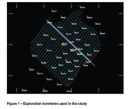
To get a true picture of the in situ rock, core is oriented. Core orientation involves the determination of the topmost or bottommost point of the top face of a drill run, which is then linked to the next run. The geotechnical holes were drilled using an automatic temperature control (ATC) orientation tool. In this way, an orientation line was drawn along the top of the core. This makes it easier to uniquely orient the core in space. This reference line is used to determine the trend and plunge of the joints. Several exploration boreholes were drilled on the site. These are shown in Figure 1. For this discussion, the authors chose borehole BO53A for illustrative purposes.
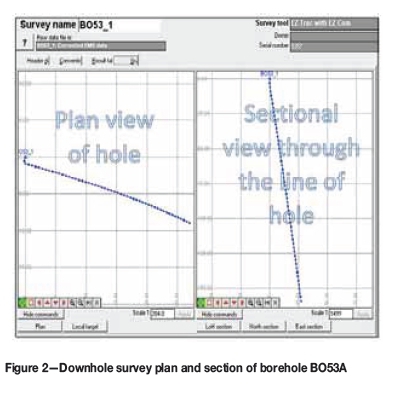
Downhole survey
Downhole surveying was carried out using a high-precision downhole survey instrument to identify any deviations from the planned drilling axis. The downhole survey plan and section of borehole BO53A are presented in Figure 2. No deviation from the drilling axis was identified. The deviation in the top portion of the hole was due to casing interference and is not an indication of true deviation. The high-precision instrument helps to prevent human error once set appropriately. The lack of deviation is advantageous since oriented core is recovered along the required drilling axis.
Logging practice
After core has been oriented it is then logged to determine the geotechnical parameters influencing pillar design. The logging process adopted at the exploration site is presented in Figure 3.
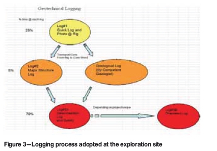
A total of 50 boreholes were geotechnically logged, some of which were oriented (BO53A, BO54A, BO55A, and BO61A). The oriented boreholes are used in this discussion as they capture much more geotechnical detail of the rock mass compared to the unoriented boreholes. BO53A is used for illustrative purposes in this paper. The logging was done in three stages. Three-metre runs were used for the assessment. Although geotechnical assessments were done throughout each drill-hole, the main zone of interest is the reef horizon and immediate hangingwall and footwall. As such, these are the areas presented in this discussion to maintain brevity and clarity.
Quick log per run - Log 1
Log 1 was a quick log per run, capturing rock type, total core recovery (TCR), solid core recovery (SCR), rock quality designation (RQD), as well as photographs and short comments for each run. Total core recovery is the sum of all measurable core recovered in one drill run, while SCR is defined as the sum of all sections of the core run that are greater than one core diameter. Sections of core with multiple mechanical breaks and handling breaks need to be considered as solid core. RQD is the ratio of the core recovered, counting pieces longer than 100 mm, to the total length of the run, expressed as a percentage. It is imperative to note that breakages due to handling and drilling have to be ignored and the core considered as being continuous at these points when calculating RQD. There has to be a guideline that enables the logger to pick these mechanical breaks. RQD is used for qualitative analysis of rock strength. Weak rock types like kimberlite may have low joint counts and thus record a high RQD. This RQD, when used in rock mass classification, gives an unrepresentative high value. Due to this, rock samples are sent to the laboratory for quantitative rock mass strength analysis.
Major structures - Log 2
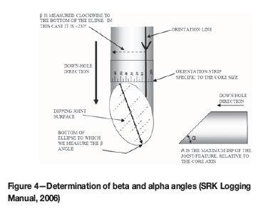
At this stage all major structures that have a bearing on the rock mass quality are logged and evaluated. The structures include shear zones, fracture zones, faults, fractures, joints, striation lineations, fold axes, veins, and dykes. Also logged at this stage are typical orientations and brittleness properties of these structures. Water staining properties of the discontinuities are recorded. When water pressure is present in a rock mass, the surfaces of the discontinuities are forced apart and the normal stress on the discontinuity is reduced. This in turn reduces the shear strength of the discontinuities. For the typical orientations, angles α and β were measured using a graduated strip and a carpenter's angle. The SRK Geotechnical Core Logging Manual (2006) was used as a guide. The alpha angle (α) is the maximum dip (α) of the feature relative to the core axis, as measured by the carpenter's angle. For the beta angle (β), the plastic calibrated strip is placed with the zero on the orientation line of the same piece of core and the tape is wrapped clockwise around the core so that the 360° point returns to the orientation line. The angle (β) is then measured, clockwise, to the bottom of the ellipse. In this convention, only the upper part of the feature is used for the measurement. The measured angles are as illustrated in Figure 4.
Error concerns in logging of major structures
It is often a challenge to determine whether a discontinuity represents an open joint or a cemented joint. For this reason, it is rational to consider a cemented joint that is open in the core as an open joint fracture, since the joint is weak, hence it easily opens up. Joint infill type has an influence on the strength of joints, so experience is required to differentiate between the various infill types. Joint strength is also affected by alteration, so knowledge of alteration analysis is critical. Estimation or averaging of joint parameters can also be a challenge since the influence of a joint set on excavation stability depends on the joint set orientation. It follows that it is advisable to assess joint conditions for individual sets as this permits the use of the most appropriate parameters for the most influential joint set.
Detailed geotechnical log - Log 3
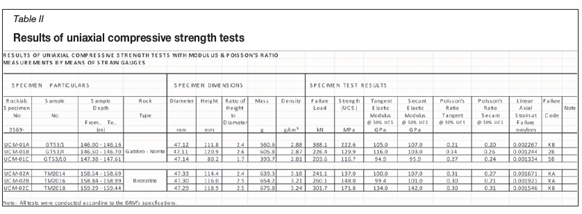
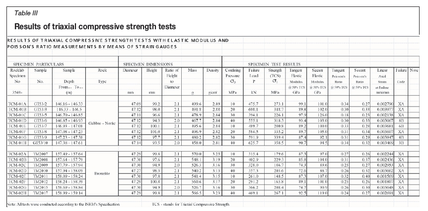
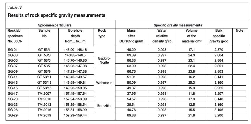
At this stage, an initial estimate of rock strength was obtained using a geological hammer. Rock strength was measured on a scale of R1 to R6, depending on its response to a knock by the hammer (SRK Logging Manual, 2006). R1 signifies highest strength while R6 is for the weakest rock. The geological hammer results were calibrated by sending samples of the rock for laboratory strength tests. The results of the laboratory strength tests are shown in Tables II and III. Table IV gives the results of rock specific gravity measurements from the laboratory tests.
For more accurate results, the authors observed that it is necessary to adopt an evaluation scale for weak rock that quantifies the level of weakness. A scale of S1 to S6 (SRK Logging Manual, 2006) can be used lest detail is lost. It was also observed that intact rock strength (IRS) is affected by elements such as microdefects, foliation, and schistosity, so for representative samples sampling has to be done in multiple orientations. Detailed geotechnical logging was done on a domain basis so as to pick sections of the core with the same geotechnical characteristics. The domains were kept to less than 3 m to preserve accuracy by avoiding over-averaging. In addition to IRS, other parameters evaluated were fracture frequency, joint conditions, cemented joint count, and microfractures.
Overall considerations in geotechnical logging
The geotechnical logging should suit the rock mass classification system to be used. It is imperative for the geotechnical logging sheet to accommodate all the parameters that will be used in the calculation of pillar strength. The logging sheet and instructions should be presented in a way which is easy to understand to minimize human errors and increase accuracy and precision.
Rock characterization from the geotechnical work done at the site
Rock mass classification systems were used to estimate the strength of the rock mass, which is an important parameter for determining pillar strength. The classification systems adopted for the project were the Q-system (Barton et al., 1974), Bieniawski's RMR (Bieniawski, 1989), and Laubscher's MRMR (Laubscher, 1990).
Link between RMR and Q-system
To compare the Bieniawski RMR and the calculated RMR, transformation Equations [20] and [21] were used.
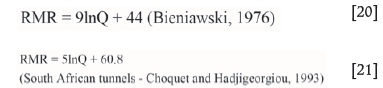
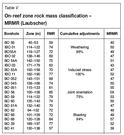
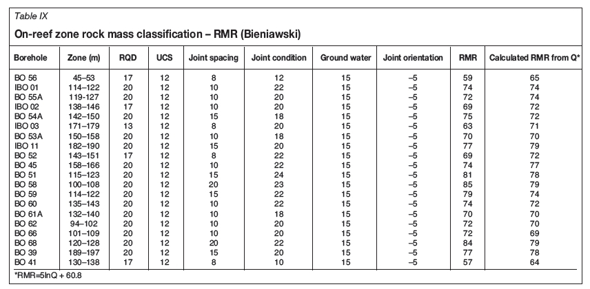
It was noted that results obtained using Equation [20] deviated from the Bieniawski RMR, so Equation [21] was used as it gave a closer correlation. Table IX gives the RMR values calculated from Q using Equation [21]. Table V gives the MRMR classification system results for the project.
Rock mass characterization
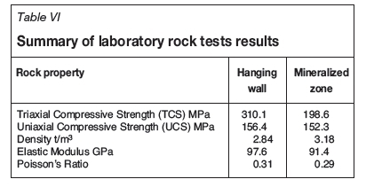
For a realistic pillar design criterion, rock mass properties were determined using laboratory uniaxial and triaxial compression tests. The parameters determined were UCS, Poisson's ratio, Young's modulus, and specific gravity. A summary of the tests results is shown in Table VI.
Pillar design considerations
The detailed logging data was processed to give some input into the pillar design at the exploration stage. For calculating strength, design rock mass strength (DRMS) was used instead of the strength of a unit cube of rock. This approach was adopted since DRMS considers all the parameters that were assessed in the logging programme which have a bearing on the pillar strength. In determining DRMS, rock mass strength (RMS) is first calculated using Equation [22] (suggested by Laubscher, 1990).

where: RMR is the total of the rock mass rating and RUCS is the uniaxial compressive strength rating determined using Bieniawski's (1989) rock mass rating system table.
To obtain the DRMR needed for calculating pillar strength, the RMS was adjusted for the effects of blasting, weathering, and joint orientation, which were 95%, 96%, and 74% respectively. The Hedley and Grant (1972) power formula was used for calculating pillar strength; however, the strength of a unit cube of rock, originally proposed as input, was replaced by DRMR, which is more representative of pillar experience. The formula used is given in Equation [23].
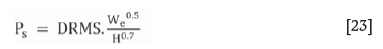
where DRMS is the design rock mass strength; Weis the effective pillar width given by 4 x Pillar area/Pillar perimeter, and H is the pillar height.
Since the maximum depth of orebody at the exploration site is less than 300 m, the mine to be established is considered to be shallow so the TAT (Equation [1]) was applied. However, the drawbacks of this theory, as discussed earlier, are still valid and further research work need to be undertaken to account for these shortfalls.
A constant safety factor (SF) of 1.6 was used for comparative analysis of the pillar strength formulae at different depth. A SF of 1.6 was used since it is the common SF for non-yielding pillars in South Africa. For calculating the square pillar width at different depths for a constant SF of 1.6, the following values were used in the SF equation (SF = Pillar strength/Pillar load):
The resultant square pillar widths at various depths for a constant SF of 1.6 are given in Table VII.
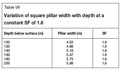
Note that the same approach was adopted to determine pillar width at different depths for a constant SF of 1.6 for different hard-rock pillar design formulae presented in this paper as applied to the project database. This was done to illustrate the uncertainty brought about by these formulae in the pillar design process. The results are as presented in Table X.
The rock mass classification data used for this research is presented in Tables VIII and IX.
Pillar design results using different hard-rock pillar design formulae
To highlight the current uncertainty in the pillar design process, the hard-rock pillar design formulae presented in this paper were used to determine square pillar sizes at different depth using the platinum exploration data. A constant SF of 1.6 was used in the calculations since it is the minimum permitted for the project. The TAT was used to determine the stresses at different depths since the mining layout is of large lateral extent, several times greater than the mining depth, and regular with same-size pillars. It is important to note that the Coates' method reduces to the usual TAT under these conditions (large width of extraction span, L) so only the TAT was used for the assessment.
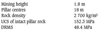
Since there is no straightforward way of calculating pillar width from the SF equation, several iterations were performed in Excel® to find the pillar width corresponding to a SF of 1.6 for each pillar strength formula. For the sake of clarity and brevity, the formulae presented earlier are not repeated here, but the values of the parameters as applied to the platinum exploration database are given and the results summarized in Table X. The parameters used in the pillar design exercise are as follows: mining height 1.8 m, pillar centres 18 m, rock density 2 700 kg/m3, UCS of intact pillar rock 152.3 MPa, and DRMS 48.4 MPa. The other parameter values for each of the formulae are as presented in Table I. The results of the pillar design exercise are summarized in Table X.
Comments on pillar design results from the different design formulae
After exploration is completed one needs a clear method for designing pillars to ensure a reliable, safe, and stable design. One is faced with an arduous task of choosing which formulae to use as the different formulae all give different pillar sizes at constant mining depth. The results show that there is no clear way of solving the pillar design problem. This points to a need for further research dedicated to resolving this problem. All the relevant factors influencing pillar design have to be considered and combined into an effective procedure or formula that pillar design practitioners for narrow-reef platinum mining can use.
The evaluation concluded that the current pillar design systems for narrow-reef platinum mining mainly consider w/h ratio and the strength of pillar material as important parameters in designing pillars. However, there are many more important factors that are not considered which have a bearing on pillar system stability. Some of the unaccounted-for factors that were discovered during the course of this research are contact of the pillar with the roof and floor, roof and floor conditions (Watson, 2010), effects of adversely oriented joints, spalling and side scaling effects, influence of pillar loading conditions, blast damage effects, influence of weak layers and weathering, impact of k-ratio, time-dependent effects, geology, fractured zones, and effects of different types of discontinuities within the rock strata.
Conclusions
A reliable pillar design system results in a layout with the desired stability. The main objective of this research was to critically evaluate the current pillar design systems used in narrow-reef platinum mining using practical experience from a large feasibility-stage platinum exploration project. The shortcomings of the current pillar design systems were highlighted. The exploration work also highlighted how rock mass classification methods can be utilized in determining the overall strength of pillars. Geotechnical parameters important for pillar design were collected by means of geotechnical logging and laboratory tests. The geotechnical logging consisted of three stages: quick log per run, major structures log, and detailed geotechnical log. Areas that require special attention in each logging stage were highlighted. It is imperative for the geotechnical logging sheet to accommodate all the parameters that will be used in the calculation of pillar strength. The logging sheet and instructions should be presented in a way that is easy to understand to minimize human errors and increase accuracy. It suffices to say that the quality of input into the pillar design system influences the quality of the results obtained.
► Pillar design results using different hard-rock pillar design formulae were significantly different, showing the uncertainty introduced by the current pillar design formulae in the pillar design process. These results show that there is currently no clear way of solving the pillar design problem. Further research has to be dedicated to resolving this challenge
► Reliable pillar design systems depend on the accurate determination of pillar load and pillar strength. There are many factors influencing these two variables that are unaccounted for in the current pillar design systems. The current systems consider pillar material strength and w/h ratio in determining pillar strength, but the failure of even high safety factor pillars is an indication of the overestimation of pillar strength because other determining factors are omitted, such as contact of the pillar with the roof and floor, roof and floor conditions, effects of adversely oriented joints, spalling and side scaling effects, influence of pillar loading condition, blast damage effects, influence of weak layers and weathering, impact of k-ratio, time-dependent effects, geology, fractured zones, and effects of different types of discontinuities within the rock strata
► The tributary area theory works well for shallow mining when the pillar layout is regular. The theory assumes that each pillar in the system carries an equal amount of load in the layout; however, pillars near permanent abutments carry less load. It is imperative to note that mining potholes and fault losses, often left out in practical mining, reduce extraction ratios, which in turn results in a lower APS than what is planned for
► The current pillar design systems for narrow-reef platinum mining were empirically developed and require pillar failure to occur in order to calibrate the pillar design empirical curves. This approach works for the design of pillars in areas lying within the empirical range used to develop the curves. However, some pillars designed this way and which meet the definition of the empirical database nevertheless fail, showing that more parameters need to be considered in the empirical database when deriving the formulae.
References
Barton, N., Lien, R., and Lunde, J. 1974. Engineering classification of rock masses for the design of tunnel support. International Journalfor Rock Mechanics, vol. 6, no. 4. pp. 189-236. [ Links ]
Bunschinger, J. 1876. Mitteilungen aus dem Mechanisch-Technishen Laboratorium der K, Technishen Hochschule inMunschen, 6. [Cited in Du etal. (2008)]. [ Links ]
Bieniawski, Z.T. 1976. Rock mass classification in rock engineering. Proceedings of the Symposium on Explorationfor Rock Engineering, Johannesburg, 1-5 November 1976. Vol. 1, Bieniawski, Z.T. (ed.). Balkema, Cape Town. pp. 97-106. [ Links ]
Bieniawski, Z.T. 1968. The compressive strength of hard rock, Journal of the South African Institute of Mining and Metallurg, vol. 8. pp. 163-182. [ Links ]
Bieniawski, Z.T. 1989. Engineering Rock Mass Classifications. Wiley, New York. [ Links ]
Bunting, D. 1911. Chamber pillars in deep anthracite mines. Transactions of the American Institute of Mining and Metallurgical Engineers (AIME), vol. 42. pp. 236-245. [ Links ]
Choquet, P. and Georgious, J. 1993. Design of support for underground excavations. Comprehensive Rock Engineering. Hudson, J. (ed.), Pergamon, vol. 4. pp. 314-348. [ Links ]
Coates, D. 1981. Rock dynamics. Rock Mechanics Principles. Department of Energy, Mines and Resources. Canada. p. 874. [ Links ]
Dave, S. 2009. Hard rock tabular mining: regional and support pillars. A lecture delivered to GDE (rock engineering) students class of 2009. University of the Witwatersrand, Johannesburg, South Africa. [ Links ]
Du, X., Lu, J., Morsy, K., and Peng, S. 2008. Coal pillar design formulae review and analysis. Proceedings of the 27th International Conference on Ground Control in Mining (ICGCM), Morgantown, WV, 29-31 July 2008. pp. 254-261. [ Links ]
Hedley, D.G.F. and Grant, F. 1972. Stope-and-pillar design for the Elliot Lake uranium mines. Bulletin of the Canadian Institute of Mining and Metallurgy, vol. 65. pp. 37-44. [ Links ]
Hoek, E. and Brown, E.T. 1980. Underground Excavations in Rock. Institution of Mining and Metallurgy, London. [ Links ]
Holland, C.T. and Gaddy, F.L. 1956. A study of the ultimate strength of coal as related to the absolute size of cubical specimens tested. Bulletin no. 112, Virginia Polytechnic. [ Links ]
Holland, C.T. 1964. The strength of coal in mine pillars. Proceedings of the 6th US Symposium on Rock Mechanics, University of Rolla. Spokes, E.M. and Christiansen, C.R. (eds.). University of Rolla, Rolla. MO. pp. 450-466. [ Links ]
Jager, A.J. and Ryder, J.A. 1999. A Handbook on Rock Engineering Practice for Tabular Hard Rock Mines. Safety in Mines Research Advisory Committee (SIMRAC), Johannesburg. [ Links ]
Krauland, N. and Soder, P.E. 1987. Determining pillar strength from pillar failure observation. Engineering and Mining Journal, vol. 8. pp. 34-40. [ Links ]
Laubscher, D.H. 1990. A geomechanics classification system for the rating of rock mass in mine design. Journal of the South African Institure of Mining and Metallurgy, vol. 90, no. 10. pp. 257-273. [ Links ]
Lunder, P.J. and Pakalnis, R. 1997. Determination of the strength of hard-rock mine pillars. Bulletin of the Canadian Institute of Mining and Metallurgy, vol. 90, no. 10. pp. 51-55. [ Links ]
Madden, B.J. 1990. An investigation into the factors affecting the strength of pillars in South African coal mines. PhD thesis, School of Mining Engineering, University of the Witwatersrand, Johannesburg, South Africa. [ Links ]
Martin, C.D. and Maybee, W.G. 2000. The strength of hard-rock pillars. International Journal of Rock Mechanics and Mining Sciences, vol. 37, no. 4. pp. 1239-1246. [ Links ]
Ozbay, M.U., Ryder, J.A., and Jager, A.J. 1995. The design of pillar systems as practised in shallow hard-rock tabular mines in South Africa. Journal of the South African Institute of Mining and Metalurgy, vol. 84, no. 8. pp. 7-18. [ Links ]
Potvin, Y., Hudyma, M.R., and Miller, H.D.S. 1989. Design guidelines for open stope support. CIM Bulletin, vol. 82. pp. 53-62. [ Links ]
Roberts, D.P., van der Merwe, J.N., Canbulat, I., Sellers, E.J., and Coetzer, S. 2002. Development of a method to estimate coal pillar loading. Safety In Mines Research Advisory Committee (SIMRAC), Johannesburg, South Africa. [ Links ]
Salamon, M.D.G. 1983. The role of pillars in mining. Rock Mechanics in Mining Practice. Budavari, S. (ed.). South African Institute of Mining and Metallurgy, Johannesburg. pp. 173-200. [ Links ]
Salmon, M.D.G. and Munro, A.H. 1967. A study of the strength of coal pillars. Journal of the South African Institute of Mining and Metalurgy, vol. 68, no. 4. pp. 55-67. [ Links ]
Salamon, M.D.G. and Oravecz, K.I. 1976. Rock mechanics in coal mining. PRD Series no. 198. Chamber of Mines of South Africa, Johannesburg. [ Links ]
Sjobergy, J. 1992. Stability and design of stope roofs and sill pillars in cut and fill and open stope mining with application to Zinkgruvan Mines. Liceniate thesis, Lulea University of Technology, Lulea, Sweden. [ Links ]
SRK. 2006. Geotechnical core logging generic internal training manual. Geotechnical Engineering Department, SRK, Johannesburg, South Africa. [ Links ]
Stacey, T.R. and Page, C.H. 1986. Practical Handbook for Underground Rock Mechanics (Series on Rock and Soil Mechanics). Trans Tech Publications. [ Links ]
Von Kimmelmann, M.R., Hyde, B., and Madgwick, R.J. 1984. The use of computer applications at BCL Limited in planning pillar extraction and design of mining layouts. Proceedings of ISRM Symposium: Design and Performance of Underground Excavations. Brown, E.T. and Hudson, J.A. (eds.). British Geotechnical Society, London. pp. 53-63. [ Links ]
Wagner, D. 1980. Pillar design in coal mines. Journal of the South African Institute of Mining and Metallurgy, vol. 80. pp. 37-45. [ Links ]
Watson, B.P. 2010. Rock behaviour of the Bushveld Merensky Reef and the design of crush pillars. PhD thesis, School of Mining Engineering, University of Witwatersrand, Johannesburg, South Africa. [ Links ]
Watson, B.P., Ryder, J.A., Kataka, M.O., Kuijpers, J.S., and Leteane, F.P. 2008. Merensky pillar strength formulae based on back-analysis of pillar failures at Impala Platinum. Journal of the Southern African Institute of Mining and Metallurgy, vol. 108, no. 8. pp. 449-461. [ Links ]
Paper received Jan. 2016
Revised paper received Nov. 2016
* Cited in Du et al. (2008)

