


Services on Demand
Article
 English (pdf)
 Article in xml format
 Article references
Indicators

Related links
-
 Cited by Google
 -
 Similars in Google
Share

 Permalink
Journal of the Southern African Institute of Mining and Metallurgy
On-line version ISSN 2411-9717
Print version ISSN 2225-6253
J. S. Afr. Inst. Min. Metall. vol.117 n.2 Johannesburg Feb. 2017
http://dx.doi.org/10.17159/2411-9717/2017/v117n2a4
WITS SPECIAL EDITION - VOLUME II
Value creation in a mine operating with open stoping mining methods
P.J. Le RouxI, II; T.R. StaceyI
IUniversity of the Witwatersrand, South Africa
IIBrentley, Lucas and Associates, South Africa
SYNOPSIS
Mining companies are under constant pressure to reduce their cost structures to sustain profitability. In mines using an open stoping mining method, dilution often has a significant effect on profitability. At Target mine in South Africa, dilution in some open stopes was found to exceed 10%, falls of ground being a major contributor to the problem. This dilution can reduce the recovered grade from 5.5 to 4.5 g/t, resulting in a potential loss of about R21 million per month based on a gold price of R240 000 per kilogram. In addition to the cost of dilution, the cost of damage to, or loss of, trackless equipment as a direct result of falls of ground in open stopes is significant. Other associated costs include transport, hoisting, secondary blasting, milling, and plant treatment of waste material. Stable open stopes are essential in order to reduce falls of ground. Back-analyses of stope instability at Target mine have indicated that conventional rock mass failure criteria are unsuitable for stope design. An alternative strain-based criterion has been developed, and has proved to be very successful, allowing the stability of open stopes to be calculated reliably. Since its implementation in 2010, dilution and equipment damage have decreased markedly, creating value for the mine.
Keywords: open stope, stope stability, stope design, dilution stress-strain index.
Introduction
Mines that make use of an open stoping mining method aim to extract only the ore, leaving the waste behind. Many orebodies have well-defined boundaries between the ore and the waste rock. In such orebodies, the introduction of waste into the ore due to overbreak dilutes the grade. In massive disseminated orebodies, dilution is less problematic. Overblasting, falls of ground, or other causes may result in dilution. A study undertaken in Canada (Pakalnis et al., 1995) found that approximately 51% of all underground metal mines utilized open stoping mining methods and, from surveys conducted at these mines, open stoping operations experienced dilutions of up to 20%, and occasionally more. Dilution of this magnitude has a significant economic impact on any mining venture. Research carried out in Australia by Capes (2009) came to the same conclusion.
Dilution has a significant effect on the viability of South African gold mines that utilize open stoping mining methods. At Target mine the dilution exceeded 10% in a number of open stopes, which could adversely impact the mine's future. This dilution can result in the reduction of the recovered grade from 5.5 g/t to 4.5 g/t, resulting in a loss of some R21 million per month (based on a gold price of R240 000 per kilogram) at current production levels of 70 000 t/month. Over the life of mine, the total loss could be in excess of R3 billion.
Capes (2009) briefly discussed the costs of dilution. Direct costs are primarily due to the removal and processing of the additional waste material; these costs are for hauling, transport, crushing, hoisting, and milling of the waste rock. Indirect costs are associated with damage to equipment due to falls of ground in open stopes during mucking. Numerous cases of such damage to equipment have occurred at Target mine.
It is obvious that a reduction in dilution and equipment damage will be of great benefit to the profitability of a mining operation. To achieve this requires the accurate prediction of instability in open stopes, and hence optimized stope design. It is not surprising that a significant amount of research into the prediction of dilution in open stopes has been undertaken, for example by Potvin (1988), Clark and Pakalnis (1997), Clark (1998), Sutton (1998), Wang (2004), Brady et al. (2005), and Capes (2009). The methods described in this research could be expected to be applicable for the design of stable stopes at Target mine. Their use will be described in this paper, as well as the development of a new approach that provided much greater accuracy in stope design and prediction of dilution at Target mine.
Open stoping at Target mine
Target mine hosts multiple reefs overlying one-another, forming an orebody approximately 180 m in thickness and 270 m wide on dip, termed the Eldorado Reefs. The dip of the reefs varies from 10° in the west to 75° in the east. In most Australian and Canadian open stoping operations, the hangingwall and footwall consist of waste rock, with the orebody dipping relatively steeply. In contrast, at Target Mine the hangingwall, sidewalls, and footwall generally consist of reef with different grades. If the stope being mined is adjacent to an existing old stope, one sidewall of this stope will be backfill. The mining direction of the open stopes is from the lowest position of the reef (on the west), progressing up towards the east, as shown in Figure 1.
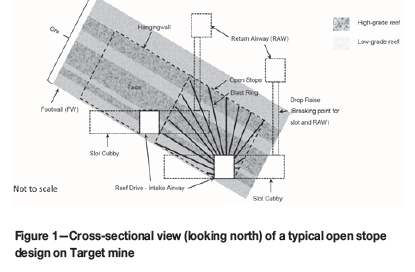
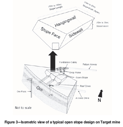
Owing to the depth of the mine, some 2300 m to 2500 m below surface, and resulting high stress levels, a destressing 'slot' is mined to create an artificial shallow mining environment in which the maximum stress does not exceed 60 MPa. This destressing slot involves narrow-reef mining on the Dreyerskuil Reef, with an average stoping width of 1.5 m. To extract the massive reefs, open stopes are excavated by blasting to mine selected reef packages within the orebody. These open stopes vary in size between 10 m and 25 m in width (span), 10 m and 35 m in height, and 10 m and 100 m in length. To establish an open stope, a reef drive is developed on strike at the lowest point where the stope will be situated, as shown in Figures 1, 2, and 3.
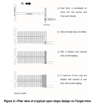
This reef drive is developed to the mining limit of that specific open stope. At the end of the open stope slot, cubbies are developed, cutting across the dip of the strata. In one of the cubbies, a drop raise is developed, holing into the top drive for ventilation. Once developed, the slot is drilled, as well as the blast rings for the open stope. When completed, the slot is blasted and cleaned using remote loading load, haul, and dump (LHD) mechanized equipment. The open stope is then created by blasting a maximum of four rings at a time, on retreat, and is cleaned using remote-loading LHDs. No personnel may enter these open stopes at any time.
Empirical database
To investigate and document the behaviour of open stopes at Target mine, and to evaluate alternative open stope design methods, a comprehensive empirical database was established based on the open stope mining information, rock mass properties, rock mass classification, and cavity monitoring system (CMS) data. The following information, from 28 case study stopes at Target mine, was included in the database.
► Planned stope volume
► Stope volume from CMS survey data
► Stope geometry: beam area (stope surface area analysed), circumference, hydraulic radius
► Rock mass properties and rock mass classification values
► Major principal stress at the open stope hangingwall and sidewall before mining the stope
► Modified stability number, N (Potvin, 1988)
► Equivalent linear overbreak slough (ELOS) (Clark and Pakalnis, 1997).
Information from the database indicated that, over an 11-year period, the major contributors to dilution in open stopes were hangingwall beam failures, poor blasting, and some sidewall failures. From all the open stopes mined on Target mine, only 28 case studies had sufficient information for this investigation. The dilution ranged from as high as 74% to as low as 1.1% for 22 of the case study stopes. 1.1 Mt of overbreak was recorded for this period in the open stopes. The remaining six stopes showed underbreak ranging from 2% to as high as 18% due to poor blasting and were not included in this study. Thus only 22 case studies were used.
The percentage dilution (% Dilution) in an open stope is calculated as follows:
% Dilution = (Measured stope volume by CMS - Planned stope volume) (Planned stope volume) x 100
Major dilution is defined as dilution greater than 10% (a mine management definition). Minor dilution is where the measured dilution is equal to or less than 10%, and underbreak is where the measured dilution is negative (<0%). At Target mine, all open stopes are designed for dilution of 5% and less, but this was rarely achieved. In half of the case study stopes, dilution was >10%, 29% had dilution <10%, and in the remaining 21%, underbreak occurred.
Prediction of stability of open stopes
The stability and design of open stopes was evaluated using empirical methods (Potvin, 1988), and numerical stress analysis methods with various rock mass failure criteria. These methods were applied to the case study stopes to evaluate their applicability.
Modified stability number
The modified stability number is used in the stability graph method (Potvin, 1988) to determine the stability of open stopes, and hence to design the stopes. This system is a modification of the Q system (Barton et al., 1974), and has particular application in the evaluation of the stability of open stopes. The stress reduction factor from the Q system is not used, and three specific modification factors are applied to take account of the effect of rock strength to stress ratio, the effect of joint orientation, and the influence of gravity. The result is the modified stability number N as shown in Tables I to III. In Tables I to III, R is the ratio of the uniaxial compressive strength (UCS) of the rock to the induced stress at the centreline of the stope surface. Details of the method are given in the original references.
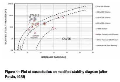
Making use of the case histories, the hydraulic radius (plan area of a stope hangingwall or sidewall divided by its perimeter) and the modified stability number N for each of the 28 case study stopes were determined. In Figure 4, the 28 case study results are plotted on the modified stability diagram (after Potvin, 1988). Although the Potvin (1988) method is not designed to determine dilution, trend lines were plotted on the diagram to bring out any correlation between percentage dilution, the modified stability number N, and hydraulic radius. It can be seen that seven of the open stopes with major dilution (>10%) plot in the 'support required' zone, with five of the case studies plotting in the transitional zone, two in the stable zone, and two in the caved zone. It would seem that there is some correlation between percentage dilution and HR/N as shown in Figure 4 and Figure 5.
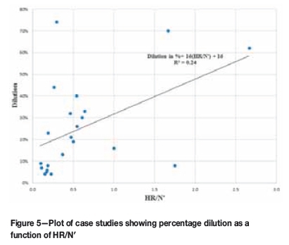
The percentage dilution, hydraulic radius (HR), and modified stability number, N for 22 of the case studies are plotted on the graphs for dilution greater than zero in Figures 5 and 6. Figure 5 simply considers percentage dilution as a function of HR/N for the surface exhibiting the most dilution. If more than one stope surface has significant dilution, this approach would not take this into account. In Figure 6, logarithmic trend lines are established for several N ranges. These trend lines represent a potential empirical approach to the design of the open stopes, since the predicted percentage dilution can be calculated making use of the equations for the lines, which are shown in the equation derived from Figure 5:
Dilution (%) = 16  + 16
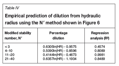
+ 16
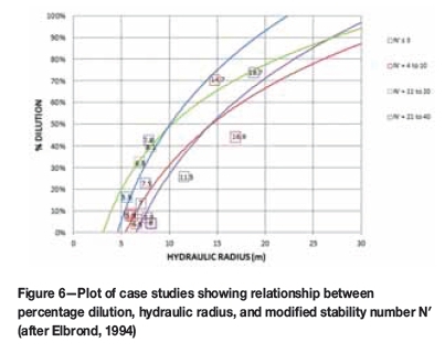
The fit of each equation to the data obtained from the 22 case studies is shown by the R2 value in Table IV, and visually in Figure 6 (after Elbrond, 1994). Unfortunately, the correlations are not good, and therefore it can be concluded that these simplified empirical approaches do not provide a sufficient level of design confidence for stopes at Target mine. The problems with this approach may be due to the sedimentary geology, the shallow dip and variable width of the orebody, and the fact that the total dilution has been measured whereas the dilution has been assessed for only one stope surface.
Equivalent linear overbreak slough (ELOS)
The dilution factor is defined as the ELOS predicted from the dilution design graph based on the modified stability number N and hydraulic radius for an open stope. The 22 case studies with dilution greater than zero are plotted on the modified stability diagram for ELOS (after Clark and Pakalnis, 1997) in Figure 7. The calculated ELOS is from 2.5 m up to 10.4 m for open stopes with major dilution (>10%). A contributing factor could be that the sidewall dilution has not been assessed for ELOS, so the calculated ELOS would be less than the total ELOS recorded. Also, in some cases the significant sidewall dilution greatly increased the hydraulic radius of the stope hangingwall, further increasing dilution, which was not predicted from the ELOS approach. The measured ELOS was based on the difference between the planned stope volume and the CMS actual stope volume, divided by the area of the surface creating the maximum dilution. In cases where significant dilution was from more than one surface, ELOS may be greatly underestimated. It should be noted that seven of the 14 cases of major dilution had significant dilution from one or two sidewalls as well as the hangingwall.
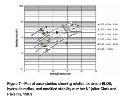
The modified stability diagram for ELOS (after Clark and Pakalnis, 1997) was further modified in an attempt to incorporate the ELOS values obtained on Target mine as shown in Tables I to III. The ELOS values for Target are much higher than those obtained by Clark and Pakalnis (1997) and Wang (2004), as shown in Figure 7. Due to the limited number of case studies, for the ranges of ELOS shown, the trend lines could not be verified. The maximum ELOS predicted by Figure 7 is greater than 2 m. The graph does not delineate the ELOS value if it is greater than 2 m, which makes it difficult to apply to many of the case histories.
Numerical stress analysis methods
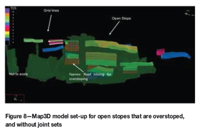
From the back-analyses on the 22 open stopes where sufficient data was available, three-dimensional stress analyses were conducted. MAP3D-SV was the numerical analysis package used to model the mining of the open stopes. The purpose of the analyses was to determine the median three principal stresses and the corresponding three principal strains at the centreline of the stope hangingwall and sidewalls for the specific mining configuration. To achieve this, strings (also known as gridlines) were placed on the boundaries of the hangingwall and sidewalls in the centre of the open stope hangingwall and sidewalls for each of the open stopes, and the actual mining extraction sequence shown in Figure 8 was simulated. It was found that the expected stresses on the boundaries of the open stope were not negative or zero due to the accuracy of the model in areas where overstoping was conducted. Overstoping is the process by which a narrow reef mining slot is blasted, creating an artificial shallow mining environment in which the open stopes will be mined, as shown in Figure 8.
The rock mass in the numerical model was assumed to be homogeneous and isotropic to simplify modelling (Wiles, 2006). The following input parameters were used in the MAP3D-SV analyses:
► Young's modulus 70 000 MPa
► Poisson's ratio 0.2
► Density 2700 kg/m3
► K-ratio 0.5
The Young's modulus, Poisson's ratio, and density values were determined from laboratory tests conducted at the University of the Witwatersrand by Le Roux (2004). The K-ratio is an estimate based on underground observations and back-analyses.
The principal stresses determined in the analyses were substituted into several rock mass failure criteria to determine whether any of these criteria would be suitable for predicting instability around open stopes at Target mine. The most widely accepted failure criteria currently used in rock engineering are the Hoek-Brown failure criterion (Hoek et al., 2002) and the Mohr-Coulomb failure criterion (Labuz and Zhang, 2012). These two criteria and the Zhang-Zhu (Zhang and Zhu, 2007), Pan-Hudson (Pan and Hudson, 1988), Priest (Priest, 2009), Simplified Priest (Priest, 2009), and Drucker-Prager criteria (Alejano and Bobet, 2012) were used in the evaluation.
Only 22 of the case study stopes proved to be appropriate with regard to the application of these criteria. From these studies, it was found that 14 open stopes had undergone hangingwall failure and eight sidewall failure, seven cases being a combination of hangingwall and sidewall failure. Major dilution occurred in nine of the 14 stopes with hangingwall failure, and minor dilution in five. For sidewall failure, it was found that five stopes had major dilution and three minor dilution. The open stopes with a combination of hangingwall and sidewall failure were included in analyses of both major and minor dilution in open stopes with hangingwall and sidewall failure. Using regression analysis (R2, a statistical measure of how close the data is to the fitted regression line), the most suitable statistical measure was determined. Using the results obtained from Map3D on the hangingwall and sidewalls for the 22 case studies simulated, the failure criteria were applied. Figure 9 and Figure 10 compare the results of application of the criteria with those obtained from the Map3D analyses.
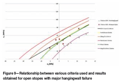
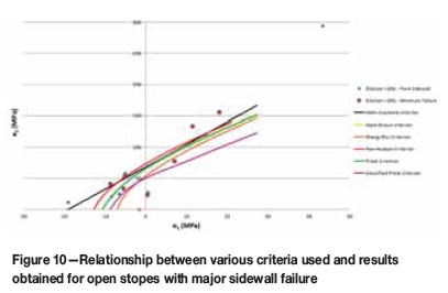
Using the stresses determined with Map3D, the various stress-based failure criteria discussed above were applied to predict failure depths into the hangingwall and sidewalls of the case study open stopes. The results obtained showed that the stress-based failure criteria either completely overestimated or underestimated the failure for most of the case studies. It can be concluded that these criteria are not appropriate for accurate design of open stopes in the Target gold mining environment.
Application of a strain-based criterion
The extension strain criterion (Stacey, 1981) was applied to the open stope case studies. Making use of the final CMS for the open stopes, the model was calibrated by modifying the modulus of elasticity until the fracture extent matched with the final CMS (after Louchnikov, 2011). By modifying the modulus of elasticity in the numerical model the principal strains would be increased or decreased. Although the resulting prediction from this criterion matched the expected failure shape in the hangingwall of the open stope, the predicted fracture propagation was significantly deeper into the hangingwall than the failure observed for Target mine. The lack of success with this strain criterion is perhaps to be expected, since the criterion (Stacey, 1981) applies to the initiation of fractures and not to failure. However, the correspondence of the failure shape suggested that a strain-based criterion could be more successful than a stress-based one.
Mean stress and volumetric strain
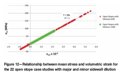
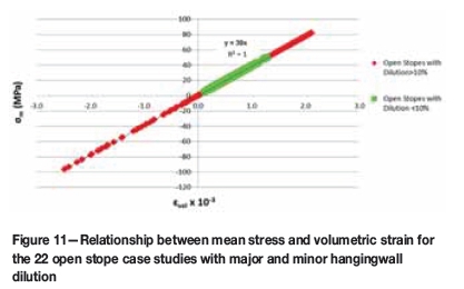
Open stopes have a three-dimensional geometry and are created in a three-dimensional stress field. It is therefore to be expected that the stability of these stopes, and the potential dilution, will be dependent on the three-dimensional stress and strain conditions around them. The commonly used Hoek-Brown and Mohr-Coulomb criteria do not consider the intermediate principal stress. To take the three-dimensional conditions into account, the mean stress, σm, also known as the octahedral normal stress, was plotted against volumetric strain, ∑vo/for open stopes with dilution greater than 10%, and dilution equal to or less than 10%, in the hangingwall and sidewalls respectively. These results showed, as expected, a linear relationship between the mean stress and volumetric strain, since stress and strain are linked in the linear numerical model by Hooke's Law (Brady and Brown, 1985).
Results obtained from the Map3D analyses on the gridlines around these 22 case studies in the hangingwall and sidewalls for major (>10%) and minor (<10%) dilution were plotted for the mean stress, σm, against volumetric strain, ενοl, as shown in Figures 11 and 12. From these plots, it is clear that the major and minor dilution for open stopes fall into distinct clusters, indicating the potential for a satisfactory three-dimensional criterion for the design of open stopes.
For the 22 case studies it was found that for open stopes with >10% dilution due to hangingwall failure, the volumetric strain and mean stress values were in the very low range, thus placing them in a relaxed or destressed environment. This low-stress environment is found when open stopes are mined very close to the narrow reef destressing or for open stopes with a large hydraulic radius greater than or equal to 9. The failure mode in these conditions would include beam failure and/or keyblock failure. Failure could also occur in the hangingwall and sidewalls where high stress conditions are encountered, such as in pillar areas or high-stress abutments at the narrow-reef destressing, resulting in stress fracturing. It should be emphasized that the open stopes with <10% dilution fell within a mean stress range where fracture propagation is minimal and hangingwall and sidewall dilation is optimal to prevent hangingwall or sidewall failure, suggesting that this method could be used to differentiate between stability and failure. The following results were obtained.
Dilution >10% from hangingwall failure occurred if σm> 50 MPa; εvol> 1.29 x 10⁻³, or σm4.8 MPa; εvol< 0,124 x 10-3 as shown in Figure 13.
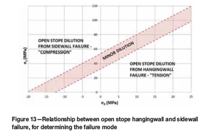
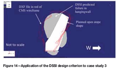
Dilution >10% from sidewall failure occurred if σm85.3 MPa; εvol> 2.19 x 10⁻³, or σm< 0.5 MPa; εvol < 0.013 x 10⁻³ as shown in Figure 14.
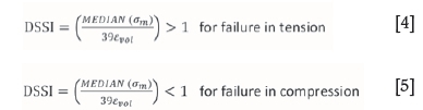
The data indicated the potential for a strain-based stability/design criterion for the Target open stopes, which has been termed the Dilution Stress-Strain Index (DSSI). The relation between mean stress σmand volumetric strain εvol can be expressed as follows:
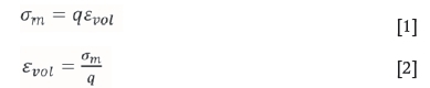
where q = 39 GPa, which is the slope of the linear trend lines in Figures 11 and 12. The DSSI is the relationship between mean stress and volumetric strain, expressed as follows:
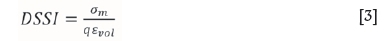
For a factor of safety of 1.0, the DSSI value is 1.0. A DSSI value of greater than 1.0 will indicate failure conditions in tension. For a set value of mean stress, if the volumetric strain were less than the threshold as determined by Figures 11 and 12, failure would occur due to relaxation. A DSSI value of less than 1.0 will indicate failure conditions in compression. This is a new criterion for determining the expected failure depth in the hangingwall or sidewalls of excavations, which does not appear in any literature reviewed. Although octahedral normal stress forms the basis of this criterion, this is a completely new method of determining failure depth: if the volumetric strain exceeds the critical value for mean stress, failure will occur. This method considers all three principal stresses and strains, which is appropriate for the three-dimensional environment of open stopes.
Application of the Dilution Stress-Strain Index (DSSI) design criterion to Target mine
A full 3D analysis of the open stopes is required, and stress and strain magnitudes must be determined on a dense grid of points adjacent to the hangingwall and sidewall surfaces. The next step is to determine the statistical median from the σ1, σ3, om, and εvolvalues for major and minor dilution in open stope hangingwalls and sidewalls. The obtained median mean stress and volumetric strain values for each case study are then plotted for major and minor dilution to determine q, which is the slope of the linear trend lines for mean stress and volumetric strain of the open stope case studies, as shown in Figures 11 and 12 for hangingwall and sidewall dilution. The σ1and σ3median results for each case study for major and minor dilution in hangingwall and sidewalls are plotted as shown in Figure 13. From these results, the failure mode (tension or compression) for major and minor dilution in open stope hangingwall and sidewalls is determined. By making use of the minor dilution data, the failure envelope cut-off can be determined as shown in Figure 13.
Application of DSSI and determination of dilution in open stopes
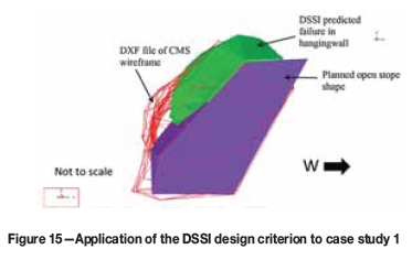
Making use of the median mean stress value σmdetermined for each case study, the DSSI can be applied for major failure in open stope hangingwall and sidewalls in Map3D. Now the open stope CMS can be imported into Map3D as a DXF file and superimposed on the numerical analysis data to compare the results, as shown in Figure 14. This is part of the calibration process. If a good correlation is found between the DSSI prediction and the open stope CMS, the criterion can be used; if not, the model calibration process must be continued until a reasonable result is obtained. To calibrate the model, the Young's modulus (E) and Poisson's ratio (v) are changed until the results match, (after Louchnikov, 2011). When the model is calibrated, the same values for Eand v must be applied for all case studies being used. The DSSI is applied for major failure in open stope hangingwall and sidewalls in Map3D for a planned open stope, and the failure depth determined. The DSSI failure lobes indicated in light grey in Figure 14 can also be exported as DXF files and compared with the design stope shape to determine the expected dilution, as shown in Figure 15. Using this information, the stope shape can be amended (reduced in size) so that the final shape corresponds with the actual required, planned shape due to the expected failure depth.
Applying the methodology shown in Figures 11 and 12, the open stope case studies were evaluated. Hangingwall and sidewall failure in open stopes can be predicted by the following equations proposed for Target mine:
After the DSSI design criterion had been established for hangingwall failure and sidewall failure on Target mine, the obtained median major principal stress σ1and median minor principal stress σ3were plotted for each of the 22 case studies. Using the obtained results for the 22 case studies, the failure mode for the open stopes with major hangingwall or sidewall dilution (>10%) could be determined. The same was done for open stopes with minor dilution (<10%). A failure envelope was established using the minor dilution trend line. By allowing for a failure envelope indicated as 'Minor Dilution' in Figure 13, upper and lower failure limits were found to be where σ1= 2.6σ3+ 54 and σ1= 2.6 σ3+ 34 respectively for open stopes with minor dilution.
Making use of the graph in Figure 13, and depending on where these results for median major principal stress σ1and median minor principal stress σ3plot for each open stope, the appropriate hangingwall or sidewall median mean stress value can be applied to the DSSI (Equation [4]). Figure 14 indicates such areas (light grey shading) around the open stope for hangingwall failure for case study 3. The minimum contour range for plotting the DSSI design criterion was set to zero and the maximum to 1, with intervals of 1 in Map3D. This means that a DSSI obtained value of >1 will be indicated as light grey on the grid plane. The predicted failure corresponded very well with an actual observed failure in the hangingwall, as shown by the CMS of the open stope plotted in red on Figure 15.
Prediction of dilution from volumetric strain
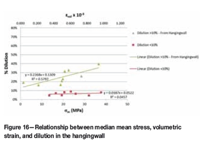
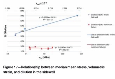
The median mean stress σmand median volumetric strain εvol results obtained from the case studies were plotted relative to the percentage dilution obtained for each case study as shown in Figures 16 and 17. This information proved useful in predicting the actual expected dilution in the open stopes from the hangingwall or sidewalls. Making use of regression analysis (R2), the trend lines for the 22 case studies were established. It was found that for dilution >10% from the sidewalls the regression coefficient (R2) was 97%, which is very good. The regression analysis indicated R2 = 58% for dilution >10% from the hangingwall.
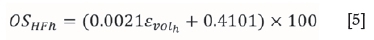
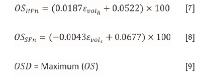
From the graphs in Figure 16 and 17, the following equations are proposed for calculating major hangingwall, major sidewall, or minor dilution in open stopes on Target mine:
If  > 1 then major sidewall dilution will occur as shown in Figure 13:
If  < 1 then major hangingwall dilution will occur as shown in Figure 13:

If  < 1 and
  > 1 then minor dilution will occur as shown in Figure 13:
where
OSHFs is the open stope hangingwall dilution in per cent for failure in compression
OSSFs is the open stope sidewall dilution in per cent for failure in compression
OSHFh is the open stope hangingwall dilution in per cent for failure in tension
OSSFh is the open stope sidewall dilution in per cent for failure in tension
OSHFn is the open stope hangingwall dilution in per cent for failure in normal open stope conditions
OSSFn is the open stope sidewall dilution in per cent for failure in normal open stope conditions.
OSD (open stope dilution) is the maximum value for the respective OS value obtained.
Making use of the graph shown in Figure 11, the relationship between open stope hangingwall and sidewall failure and ultimately dilution can be determined. This is done by plotting the obtained σ1and σ3median results for each separate case study on Figure 13 and reading off the graph whether there will be expected hangingwall dilution, sidewall dilution, or minor dilution. Thus for sidewall dilution, Equation [5] will be used; for hangingwall dilution, Equation [6] will be used. For minor dilution Equations [7] and [8] will be used. After calculating the expected dilution using the relevant equations, only the maximum calculated dilution (OSD) value is used for the open stope being evaluated.
Comparison of calculated open stope dilution to other empirical methods
The results predicted using the DSSI criterion were compared with the stope behaviour predicted with the stability number N' and hydraulic radius, as calculated for the modified stability graph (Potvin, 1988) as shown in Figure 4, and the site-specific average expected dilution as shown in Figures 5 and 6. The OSD method using the DSSI criterion provided reliable estimates of the depth of failure for all the available data. The Potvin (1988) modified stability diagram clearly shows the difference between stable and caving conditions for the case studies. The method used by Elbrond (1994) tended to overestimate the amount of dilution expected at Target mine, probably due to the narrow orebody that the method was developed from.
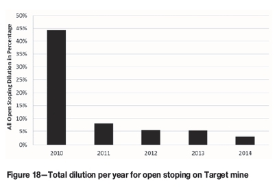
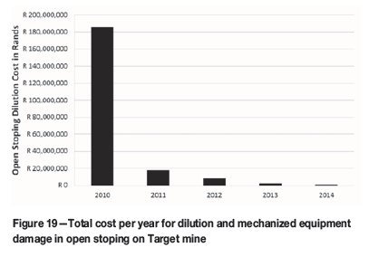
Since 2011, when the DSSI design criterion was applied at Target mine, a significant reduction in dilution has been recorded, as shown in Figure 18. With the ability to predict dilution in open stopes, these stopes could be re-designed to 'fail' to the desired final open stope shape. The DSSI design criterion has clearly influenced the sustainability and economics at Target mine, as shown in Figure 19. The financial benefit has been quantified, and this has proved the value of the design approach using the new DSSI criterion. There is no reason why the design approach could not have the same impact on any other mining operation: it has been shown to be equally applicable to different mining and geological environments (Le Roux, 2015).
Conclusions and recommendations
The objective of the research described in this paper was to develop an improved method of calculating the expected failure depth into the hangingwall and sidewalls of open stopes, and hence determine potential dilution in open stopes. Existing methods of evaluating open stope stability, which include empirical methods and stress analysis methods with stress-based rock mass failure criteria, were assessed. Rock mass properties, rock mass classifications, blast design, blast techniques, the stress-strain environment, and the hydraulic radius of the stope all have some effect on, or play a part in, the evaluation of dilution. It was found that the stress-strain environment also plays a significant role in the behaviour of open stopes at depth. Twenty-two case study stopes at Target mine, which yielded sufficient information for the research, were selected. The results of predictions of the depths of failure into the open stope hangingwall and sidewalls, based on application of the new DSSI design criterion, allowed open stopes to be redesigned to 'fail' up to the required stope shape, thus reducing dilution.
This research has contributed to the understanding of rock behaviour in an open stope environment, and identified a design methodology to reduce dilution. It also illustrated that, even with very limited information available (Le Roux, 2015) relatively accurate results could be obtained for the open stope design. This is significant, since when a new mine is designed there is very limited information available, and the expected dilution usually cannot be determined with any confidence. The design approach developed in this research allows the failure depth into the hangingwall and sidewalls of open stopes to be estimated with greater success, and dilution can be calculated for use in mine design as shown in Table V. Proof of the value of the new DSSI design criterion is the significant impact that it has had on the economics of Target mine, and that it has ensured the future of mining at this operation. It has in fact created substantial value for the mine.
Acknowledgements
The authors would like to thank Harmony Gold Mining Company Limited for the privilege of presenting this research. The permission to include data and make use of equipment, as well as the assistance received from colleagues at Brentley, Lucas & Associates, Mining Consultants, is greatly appreciated.
References
Alejano, L.R. and Bobet, A. 2012. Drucker-Prager criterion. Rock Mechanics and Rock Engineering, vol. 45. pp. 995-999. [ Links ]
Barton, N., Lien, I.R., and Lunde, J. 1974. Engineering classification of rock masses for design of tunnel support. Rock Mechanics, vol. 6. pp. 186-236. [ Links ]
Brady, B.H.G. and Brown, E.T. 1985. Rock Mechanics for Underground Mining. Allen and Unwin, London. [ Links ]
Brady, T., Pakalnis, R., and Clark, L. 2005. Design in weak rock masses, Nevada underground mining operations. Proceedings of the Annual General Meeting of the SME, salt Lake City. 9 pp. [ Links ]
CAPES, G.W. 2009. Open stope hangingwall design based on general and detailed data collection in rock masses with unfavorable hangingwall conditions. PhD thesis, University of Saskatchewan. [ Links ]
Clark, L. and Pakalnis, R. 1997. An empirical design approach for estimating unplanned dilution from open stope hanging walls and footwalls. Annual General Meeting of the CM, Calgary, Alberta. [ Links ]
Clark, L. 1998. Minimizing dilution in open stope mining with a focus on open stope design and narrow vein longhole blasting. MSc thesis, University of British Columbia. [ Links ]
Elbrond, J. 1994. Economic effects of orelosses and rock dilution. CIM Bulletin, vol. 87, no. 978. pp. 131-134. [ Links ]
Hoek, E., Carranza-Torres, C.T., and Corkum, B. 2002. Hoek-Brown failure criterion-2002 edition. Proceedings of the Fifth North American Rock Mechanics Symposium (NARMS-TAC). Hammah, R., Bawden, W., Curran, J., and Telesnicki, M. (eds.). University of Toronto Press, Toronto. pp. 267-273. [ Links ]
Labuz, J.F. and Zhang, A. 2012. Mohr-Coulomb failure criterion. Rock Mechanics and Rock Engineering, vol. 45. pp. 975-979. [ Links ]
Le Roux, P.J. 2004. Project on rock mass properties for the Free State, mechanical properties of rocks and rock masses. University of the Witwatersrand, South Africa. [ Links ]
Le Roux, P.J. 2015. Measurement and prediction of dilution in a gold mine operating with open stoping mining methods. PhD thesis, University of the Witwatersrand. 227 pp. [ Links ]
Louchnikov, V. 2011. Simple Calibration of the Extension Strain Criterion for its use in Numerical Modelling. Australian Centre for Geomechanics, Perth. pp. 85-96. [ Links ]
Pakalnis, R.C., Poulin, R., and Hadjigeorgiou, J. 1995. Quantifying the cost of dilution in underground mines. Mining Engineering. pp. 1136-1141. [ Links ]
Pan, X.D and Hudson, J.A. 1988. A simplified three-dimensional Hoek-Brown yield criterion. Rock Mechanics and Power Plants. Romana, M. (ed.). Balkema, Rotterdam. pp. 95-103. [ Links ]
Potvin, Y. 1988. Empirical open stope design in Canada. PhD thesis, University of British Columbia, Vancouver. [ Links ]
Priest, S.D. 2009. Comparisons between selected three-dimensional yield criteria applied to rock. Rock Mechanics and Rock Engineering, vol. 43. pp. 379-389. [ Links ]
Stacey, T.R. 1981. A simple extension strain criterion for fracture of brittle rock. International Journal of Rock Mechanics and Mining Sciences & Geomechanics Abstracts, vol. 18. pp. 469-474. [ Links ]
Sutton, D. 1998. Use of the modified stability graph to predict stope instability and dilution at Rabbit Lake Mine, Saskatchewan. Design Project, University of Saskatchewan, Canada. [ Links ]
Wang, J. 2004. Influence of stress, undercutting, blasting, and time on open stope stability and dilution. PhD thesis, University of Saskatchewan. [ Links ]
Wiles, T.D. 2006. MAP3D user's manual. Mine Modelling (Pty) Ltd, Mount Eliza, Victoria, Australia. [ Links ]
Zhang, L. and Zhu, H. 2007. Three-dimensional Hoek-Brown strength criterion for rocks. Journal of Geotechnical and Geoenvironmental Engineering, vol. 133, no. 9. pp. 1128-1135. [ Links ]
Paper received Apr. 2016
Revised paper received Dec. 2016

