


Services on Demand
Article
 English (pdf)
 Article in xml format
 Article references
Indicators

Related links
-
 Cited by Google
 -
 Similars in Google
Share

 Permalink
Journal of the Southern African Institute of Mining and Metallurgy
On-line version ISSN 2411-9717
Print version ISSN 2225-6253
J. S. Afr. Inst. Min. Metall. vol.117 n.2 Johannesburg Feb. 2017
http://dx.doi.org/10.17159/2411-9717/2017/v117n2a1
WITS SPECIAL EDITION - VOLUME II
A CFD model to evaluate variables of the line brattice ventilation system in an empty heading
T. Feroze; B. Genc
School of Mining Engineering, University of the Witwatersrand, South Africa
SYNOPSIS
Blind headings in room and pillar coal mines are a major source of methane and coal dust. Most methane and coal dust explosions therefore occur in the blind headings. The primary cause of these explosions is the disruption of the local ventilation system. Line brattice (LB) ventilation systems are used to ventilate blind headings by directing air from the last through road (LTR) into the heading. The amount of air available to ventilate the face of the empty heading depends on the heading dimension, settings of the LB, and velocity of air in the LTR. LBs are commonly installed by underground supervisory staff based on work experience, which may result in ineffective ventilation. The correct installation of LBs remains a challenge.
In this study, a validated computational fluid dynamics (CFD) model has been used to analyse the effect of the LB ventilation system variables on the air flow rates close to the face of the empty heading. Full-scale three-dimensional models with various heading heights, heading depths, LB settings, and LTR velocities were simulated. The air flow rates and patterns at various locations inside the heading were analysed. A comparative study was carried out to quantify the effect of each of these system variables on the flow rates close to the face of the heading. Based on the findings, a user-friendly numerical model was formulated that can be used to estimate the flow rate close to the face of an empty heading for different practical settings of the system variables. This model can help the supervisory staff to swiftly implement the ventilation plan according to the regulations and the mine standards. The model can also serve as part of the curriculum for educating future mining engineers.
Keywords: coal mining, mine ventilation, line brattice , empty heading, modelling, CFD.
Introduction
Ventilation is one of the most important aspects of underground coal mining. Mines have been using different techniques for centuries to provide sufficient air for breathing and to removing harmful contaminants. Initially natural ventilation was used in which the flow was created using the difference in masses of air in the intake and return shafts due to differences in temperature and hence density. These mines were abandoned once the natural ventilation was insufficient for the growing size of the mine. The introduction of steam-driven fans marked the beginning of mechanical ventilation. These were superseded by the powerful electrically driven fans currently in use. Growing awareness of the requirements for worker health and safety resulted in the mining industry striving for better practices, resulting in an early guideline for ventilation design in 1929 (Reed and Taylor, 2007).
The ventilation of underground mines, irrespective of the type of mine and mining method, is divided into two broad aspects -primary ventilation and secondary or auxiliary ventilation. The primary ventilation is responsible for the total volumetric flow through the mine and is calculated based on the pressure, size, complexity, equipment used, production rate, etc. The auxiliary ventilation is responsible for the ventilation of the development ends, production zones, and facilities disconnected from the main circuit; that is, where there are no through ventilation connections. Auxiliary ventilation is the most important but also the most difficult to achieve (Bise, 1996). Disruptions to the auxiliary ventilation system are considered to be the primary cause of methane and coal mine dust explosions (Creedy, 1996), which have resulted in a large number of causalities in coalfields around the world (Phillips and Brandt, 1995; Dubinski et al., 2011; Phillips, 2015).
A line brattice (LB) ventilation system forms part of the auxiliary ventilation circuit and is used to ventilate blind headings, both when being mined and when standing, by channelling the intake air from the last through road (LTR) to the working section and across the face (Cheremisinoff, 2014). It is manufactured of plastic sheeting with or without fabric reinforcement (Hartman et al., 2012). The design and installation of a LB is a fundamental issue for ensuring sufficient air supply for effective ventilation (Aminossadati and Hooman, 2008). Various studies have been undertaken to understand the performance of the LB ventilation system and ventilation of the working face. The earlier studies revealed that a LB is essential for the prevention of recirculation and for the control of respirable dust and methane in the face area (Tien, 1988). It was found that an upstream LB system increases the penetration of air by 46% with recirculation of only 10% compared to a downstream LB system with penetration of 16% and recirculation of 50% (Meyer et al., 1991; Meyer, 1993). The use of an air curtain was shown to be very effective in resolving the problem of dust isolation at a fully mechanized working face (Wang et al., 2011). A comparison of different auxiliary ventilation systems showed that the LB is the most suitable system for directing dust particles away from the face (Candra et al., 2014), and a hybrid brattice system can be effectively used to mitigate dust dispersion from the face and keep the workplace safe for the miners (Candra et al., 2015). Several studies have been undertaken to ascertain the effect of LB setback distance on the ventilation of a heading. A reduction in the setback distance and increase in the quantity of air at the exit of the LB has been shown to reduce dust and methane levels and improve ventilation (Lihong et al., 2015; Taylor et al., 2005; Goodman and Pollock, 2004, Thimons et al., 1999). A combination of brattice-exhausting system has been found to yield the best ventilation performance (Sasmito et al., 2013). arious studies by Wala and Petrov on the effect of setback distance and the other system variables on the ventilation of the empty headings have shown that 70-80% of the air exiting the LB does not even reach the face of the heading (Wala et al., 2002, 2004; Petrov et al., 2013).
Despite these studies, no models are available to estimate the effect of all the system variables associated with the LB system on ventilation. In the absence of such models, the installation is undertaken using past experience. The air flow close to the face of the heading is increased by increasing the distance of the LB from the wall and/or increasing the LTR velocity, or by using an auxiliary fan. This may lead to improper ventilation, and the correct installation of LBs is still a challenge. The present study was undertaken to quantify the effect of heading dimensions (depth and height), LB settings (LB length in the LTR, LB angle in the LTR, LB length in the heading, LB to wall distance in the heading), and LTR velocity on the ventilation of an empty heading using computational fluid dynamics (CFD). Models to calculate the effect of each of these variables were developed to facilitate the correct and quick installation of the LB. This study is part of a larger project that was undertaken using CFD to quantify the effect of various system variables related to the ventilation of headings using auxiliary ventilation systems in different mining scenarios.
Research matrix
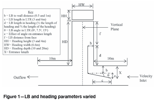
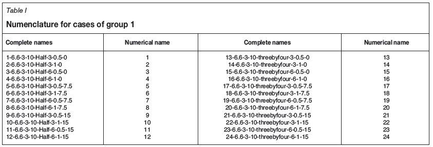
Four sets of heading dimensions (W x H x L): 6.6 x 3 x 10 m (group 1, cases 1-24), 6.6 x 3 x 20 m (group 2, cases 2548), 6.6 x 4 x 10 m (group 3, cases 49-72), and 6.6 x 4 x 20 m (group 4, cases 73-96) were used for this study. These heading dimensions were chosen by considering the most common dimensions of headings in South African coal mines, and also to cover a range of scenarios sufficient to carry out comparative analysis and capture the effect of heading height and depth. Lower seam heights are currently being investigated, but are not considered in this paper. The research was organized in such a way that there are 24 base cases in each group. The LB settings shown in Figure 1 were varied within each group in such a way that sets of cases became available within each group and between groups as well. In order to calculate the precise effect of each system variable through comparative analysis, one variable in each case of a set was varied while the others were kept constant. The cases of each group were simulated with three LTR velocities equal to 1 m/s, 1.5 m/s, and 2m/s. The sequence of cases in all groups was kept the same, as given in Table I for group 1. The 24 cases in each group were named using the syntax: case number - heading width - heading height -heading length - LB length inside heading - LB length in LTR - LB to wall distance in heading - LB angle in LTR. The sets of cases formed in this study to analyse the effect of the system variables are given in Table II.
Numerical modelling of the LB ventilation system in CFD
Model geometry and meshing
ANSYS Design Modeler and Mesher were used to model and mesh the geometries. The length of the LTR modelled on both sides of the heading was kept constant at 10 m for all the cases as shown in Figure 1. As far as possible a structured, conformal hexahedral mesh aligned with the direction of flow was created for all the geometries to avoid false diffusion and reduce the number of nodes as compared to a tetrahedral mesh. Inflation layers, where required, were used at the boundaries of the geometries to allow a smooth transition from the laminar flow near the wall to turbulent flow away from the walls. A fine-sized mesh equal to 0.04 m was used for geometries of all the cases to resolve the salient features of flow and reduce the interpolation errors. The number of nodes used varied between 8.5 million and 25 million. The final mesh size was selected after undertaking a grid independence test. This was carried out using mesh sizes of 0.1 m, 0.075 m, 0.04 m, and 0.03 m. A mesh size of 0.04 m was found to be appropriate, with less than 1% deviation with further reduction in mesh size.
Numerical calculations
Velocity inlet and outflow boundary conditions at the inlet and outlet, with the wall boundary condition at all the boundaries, was used as shown in Figure 1. Continuity and momentum equations along with the k-ε realizable turbulence model with enhanced wall treatment were solved using ANSYS Fluent. The details of the boundary conditions and the turbulence model are available in the software manual (ANSYS, 2015). The numerical model used for this research was validated using the study by Feroze and Phillips (2015) as well as the case study in this paper. The solution was calculated using a second-order scheme. The iterative process for all the cases was stopped when the desired convergence was achieved. Furthermore, the convergence in all the cases was judged by monitoring and ensuring that:
► Overall mass conservation was satisfied at the inlet and outlet of the domain (property conservation)
► The residual decreased to 10-5 (convergence criterion)
► The surface monitor of the integral of the velocity magnitude on a vertical plane, defined in the domain as shown in Figure 1, converged properly.
Results and discussion
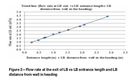
To develop an initial mathematical model for the estimation of air flow rate close to the face of the empty heading (0.5 m from face) only the first 12 cases of group 1, simulated with a LTR velocity of 1 m/s, were examined. These cases are termed the standard cases in this study. This analysis was then refined using comparative analysis by considering the effect of all the system variables on all the cases. The flow rates at the exit of the LB for the standard cases showed a direct proportionality with the product of the entrance length and the distance of the LB to the wall of the heading, as shown in Figure 2. Since this product is the same for cases where the LB was used with zero angle and the same LB to wall distance (same for cases 1 and 3 and 2 and 4), out of the first four cases only case 1 and 2 were used.
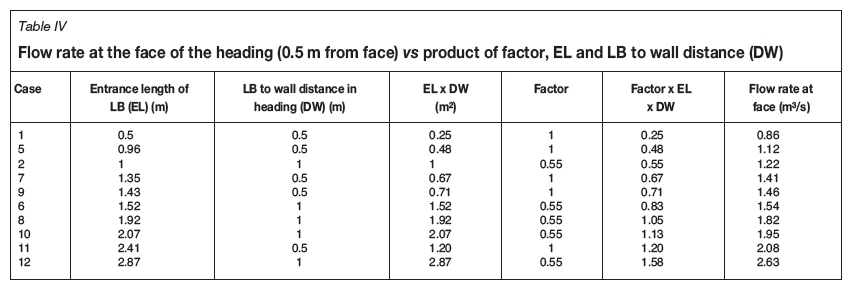
The flow rates close to the face of the heading for the standard cases, however, did not show this proportionality. Therefore, a comparison of the flow rates at the exit of the LB and the face of the empty heading was carried out as shown in Table III. The comparison showed that the difference in flow rates at the exit of LB and face of the empty heading for cases (2, 4, 6, 8, 10, and 12) with 1 m distance of LB to wall was around 65%, and 9% with 0.5 m distance (cases 1, 3, 5, 7, 9, and 11). To cater for this, and to keep the calculations simple, a factor equivalent to unity for cases with 0.5 m LB to wall distance in the heading and 0.55 for 1 m distance was used, as shown in Table IV. The relationship between the two plotted parameters with the factor is shown in Figure 3 and given by Equation [1].
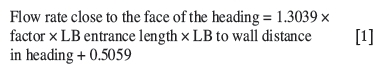
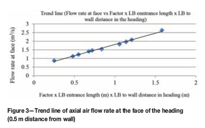
However, Equation [1] can only be used to estimate the flow rate close to the face of the heading for the ten cases given in Table IV, and when the LTR velocity is 1 m/s. To find an expression that could be used for any heading height, LTR velocity, and a range of LB settings, further analysis of the results was carried out and is discussed the following sections.
Effect of change in LTR velocity
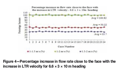
The results showed that for all the groups the average percentage increase in the flow rate close to the face with increasing LTR velocity was approximately equal to the corresponding percentage increase in the LTR velocity (maximum average difference of less than 2%). The results for all the groups were very similar, therefore this increase is illustrated here only for the cases in group 1 (Figure 4).
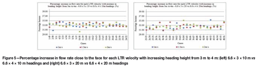
Effect of change in heading height
The percentage increase in the flow rate close to the face with increasing height of heading (that is 6.6 x 3 x 10 m vs 6.6 x 4 χ 10 m and 6.6 χ 3 χ 20 m vs 6.6 χ 4 χ 20 m is given in Figures 5. The results show that the average percentage increase in flow rate was approximately equal to the corresponding percentage increase in height of the heading (maximum average difference of less than 1%).
LB length and angle in LTR
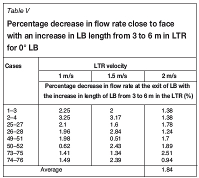
The effect of changes in length and angle of the LB in the LTR for a LB used at an angle is already catered for in Equation [1] by using the product of the entrance length and distance of the LB from the wall in the heading. The viscous effect due to the increase in length of the LB in the LTR when used at zero angle was calculated by comparing the flow rates of the set of cases with different LB lengths in LTR and similar remaining settings as shown in Table V. It was found that the flow rate on average decreased by 0.61% per 1 m increase in LB length. This was approximated as 1% decrease per 2 m increase in the LB length for simplicity of calculation.
LB length in heading and distance from face
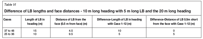
The length of LB used inside the heading for the standard cases (10 m deep heading) was 5 m. The flow rate measurements were taken at a distance of 4.5 m from the exit of the LB and 0.5 m from the face. The effect of changes in this length of LB and distance from the face was ascertained by comparing the standard cases with the cases of the 20 m deep heading (group 2 with a similar heading height of 3 m). A comparison of lengths and distances from face of LB between the standard and cases from group 2 is given in Table VI. In the cases of group 2, when a 15 m long LB was used the distance of the LB from the face was 4.5 m, similar to the standard cases. Therefore, such cases of group 1 and the standard cases were compared to capture the effect of the change in LB length. This was then used to find the effect of the distance of the LB from the face by comparing the standard cases with the cases of group 2 where a 10 m long LB was used.
LB length in the heading
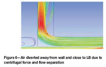
Before discussing this comparison, it is necessary to understand how the LB to wall distance and LB length inside the heading affect the flow of air. The main feature of the air flowing through the channel between the LB and the wall of heading was the propelling of air due to centrifugal force and flow separation close to the LB and away from the wall at the turn into the heading, as shown in Figure 6. As a result, the air flow at the exit of the LB was not uniform, and the air was more concentrated close to the LB (due to higher velocity).
It was found that part of the air leaving the LB is diverted towards the left wall of the heading; air close to the LB turns first and as the air moves farther away from the LB exit the effect becomes more marked, as shown in Figure 7 (the movement of air in the centre of the heading has been omitted). This reduces the amount of air actually reaching the face after exiting the LB. Consequently, when the variation in flow rate at the exit of the LB was high, a greater proportion of the air was diverted before reaching the face. Furthermore, the flow of air moving through a narrow channel is higher than in a wider channel. Hence the reduction in flow rate was much greater with 1 m LB to wall distance (Table III). However, it was found that this reduction decreases with increasing length of the LB in the heading, as the air becomes uniformly distributed at the exit of LB with this increase in length (similar to fluid flow in a pipe or channel).
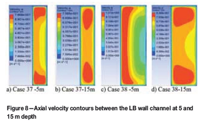
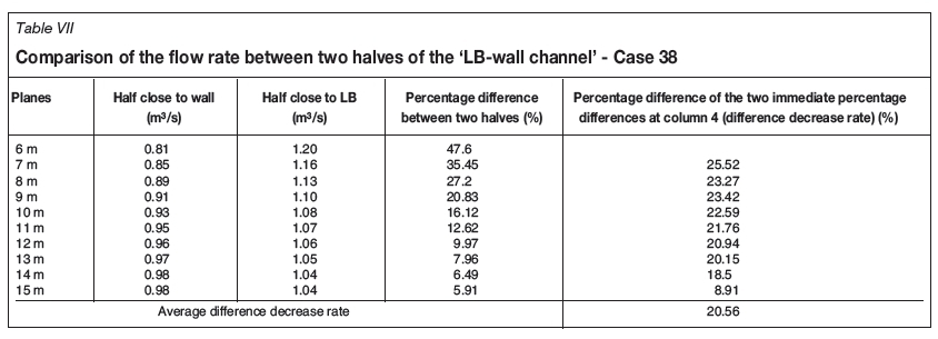
To quantify the effect of the increase in LB length in the heading on this flow rate reduction, cases with LB to wall distances of 0.5 m and 1 m in the long heading (with 15 m long LB, the maximum for this study) were analysed. This was done by constructing eleven equally-spaced vertical planes inside the channel between the LB and the wall of the heading. The first plane was constructed at a depth of 5 m. These vertical planes were split into two halves equal to 0.25 m and 0.5 m each for the 0.5 m and 1 m LB to wall distances respectively, and flow rate through these halves at each depth was calculated. All the cases of each category (0.5 m and 1 m wall distance) showed similar results. Therefore, only one case from each category is presented here, i.e. case 37 with 0.5 m LB to wall distance and case 38 with 1 m distance. The rest of the configurations are the same for both the cases. The detailed results are given in Tables VII and VIII. The difference in flow rates was found to be around 50% at 6 m depth, reducing to approximately 5% at the depth of 15 m for case 38 (1 m wall distance). The difference in flow rates between the two halves of the planes constructed for case 37 (0.5 m wall distance) was very low -around 5% even at 6 m depth and close to zero at 10 m depth (LB length of 10 m). To illustrate the impact of length on the air flow variation, the velocity contours at depths of 5 and 15 m are shown in Figure 8 for both the cases. It can be seen that the increase in LB length had a greater effect at a LB to wall distance of 1 m (as flow rates were already very uniform with 0.5 m LB to wall distance).
It was therefore concluded/assumed that for the air flow in the channel between the LB and wall of the heading to become uniform (negligible difference in the flow rates between the two halves at LB exit), a minimum length of LB is required. This length was found to vary with the LB to wall distance in the heading, being 15 m and 10 m for the 1m and 0.5 m LB to wall distance in heading respectively. Therefore an increase of 0.1 m in the LB wall distance from 0.5 m requires an additional length of 1 m over the 10 m length of LB to evenly disperse the air flow at the exit of the LB.
In Tables VII and VIII the percentage decrease rate, i.e. how the difference was decreasing with each metre increase in length of the LB, is also shown (percentage difference between the two immediate percentage differences). The average decrease rate for case 38 was approximately 20%, and for case 37 approximately 57%. Although the decrease rate for the case with 0.5 m wall distance was greater, the overall effect on the difference in magnitude of the flow rates in the two halves of the planes (constructed in the channel between the LB and wall of the heading) was much higher for the 1 m LB to wall distance.
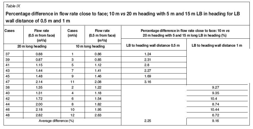
► Factor for length of LB in heading-The distance of the LB from the face of the heading is the same (4.5 m) for the standard case and cases 37-48 of group 2 (15 m long LB) (Table VI). Therefore, a comparison of these cases was used to calculate the effect of the length of LB. The percentage difference between the flow rates at the face of the heading for this set of cases was calculated and is given in Table IX. The average difference between the set of cases with 5 m LB and 15 m LB (from 10 m and 20 m headings) was found to be approximately 2.25% when the LB to wall distance in the heading was 0.5 m, and 9.16% for 1 m distance.
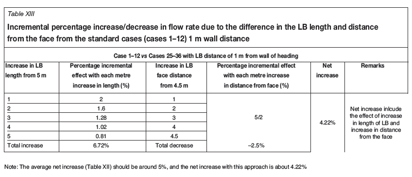
This increase in flow rate was caused only by the difference in the length of the LB. As seen in Tables VII and VIII, the average rate of decrease in the difference between the halves of the LB exit was 20% and 57% per metre increase in LB length for cases with LB to wall distances of 1 m and 0.5 m respectively. Therefore, it was concluded that the effect of increase in the length of the LB from the standard 5 m should also be incremental, changing at the rates given above. These incremental factors for each metre increase in LB length above 5 m are calculated in Tables X and XI for cases with 1 m and 0.5 m distance of the LB from the wall of the heading. The average percentage difference in flow rates close to the face of the heading with 5 m and 15 m long LB's were equated using the incremental factors. The incremental factor was calculated up to a difference of 10 m (15 m length of LB) for 1 m distance of LB from the wall of the heading and 5 m (10 m length of LB) for 0.5 m distance (to cater for the effect of flow rate variations at the exit of the LB, see Tables VII and VIII). The increment was found to be 2% for the first metre increase in LB length in the heading (from the 5 m standard cases) for the 1 m wall distance, and 1% for the 0.5 m wall distance. For a further increase in length this percentage was incremented at 80% and 43% of the previous increment for the 1 m and 0.5 m wall distances respectively.
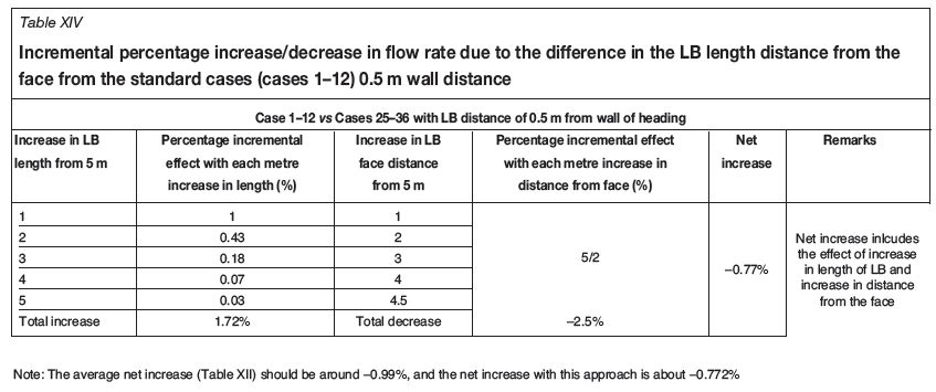
► Distance of LB from face. As discussed in Table VI, both the length of the LB and the distance from the face of the heading are different for the standard cases and the cases of group 2 using a 10 m long LB (cases 25-36). Therefore, these cases were used to estimate the effect of the distance of the LB from the face of the heading. The difference in flow rate close to the face between these 12 cases is given in Table XII. The average difference was approximately -1% when the distance of the LB from the wall in the heading was 0.5 m, and 5% for 1 m distance.
When the distance from the exit of the LB to the face increased beyond 4.5 m (standard case distance), the increase in travelling distance increased the frictional effect between the air and wall of the heading, reducing the quantity of air reaching the face. A 1% reduction in flow rate per 2 m increase in this distance, along with the previous considerations for length of the LB, was used. The estimated flow rates were calculated for the set of cases with the LB 1 m and 0.5 m from the wall of the heading, as shown in Tables XIII and XIV respectively.
Summary of the rules for using Equation [1]for any heading dimension
Keeping in view the above discussion, Equation [1] could be used to estimate the flow rate for the rest of the cases and for any other case falling within the boundaries of the studied cases, with the following conditions.
► Factor-The factor used in Equation [1] can be interpolated for any wall distance between 0.5 and 1 m (between the value of 1 and 0.55)
► Velocity-For LTR velocity greater than or less than 1 m/s, increase or decrease the flow rate calculated using Equation [1] according to the proportional increase or decrease in velocity
► Heading height-Increase or decrease the flow rate calculated using Equation [1] proportional to the percentage increase or decrease in height of the heading (as compared to 3 m)
► Length of LB in heading
- 1 m LB to wall distance - Use a factor of 2% for the first metre increase in length from the 5 m length. For a further increase in LB length, increase by 80% the previous increase in length up to a maximum of 10 m. Add the cumulative effect and increase the percentage calculated using Equation [1]
- 0.5 m LB to wall distance - Use a factor of 1% for the first metre increase in length from the 5 m length. For a further increase in LB length, increase 43% of the previous metre increase in length up to a maximum of 5 m. Add the cumulative effect and increase the percentage calculated using Equation [1]
- Any other LB to wall distance-Interpolate to find the percentage for the first metre increase in length, the reduction factor, and the number of metres to calculate the cumulative effect
► Distance of the LB from the face: Use a factor of 1% for every 2 m increase/decrease in distance from the 4.5 m distance (distance from face). Add the cumulative effect and decrease/increase the same percentage amount of flow as calculated using Equation [1]
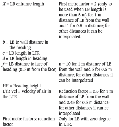
► Length of LB in the LTR: The effect of the change in the length of the LB in the LTR for a LB used at an angle is already catered for in the expression by using the product of the entrance length and distance of the LB from the wall in the heading. However, for the LB with zero angle in the LTR, the viscous effect for an increase in length of the LB of more than 3 m is estimated at 1% decrease in flow rate per 2 m increase in the length of the LB.
Generalized equation
Given the conditions above, a generalized equation to estimate the flow rates at the exit of the LB was developed to simplify the solution procedure. All the conditions given above were incorporated in the formulation of this equation.
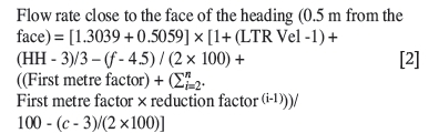
where
Validation case study
Validation of a numerical model is required to demonstrate its accuracy so that it may be used with confidence and that the results can be considered reliable. The present validation study was carried out in the Kriel Colliery, which is situated 120 km east of Johannesburg and 50 km southwest of Witbank. The velocity of air at a number of locations inside a heading ventilated using a LB was measured. A comparison of the in situ measurements with the numerical results showed that the numerical results are in line with the experimental results and the k-ε realizable model is suitable for carrying out studies related to the ventilation of a heading using a LB.
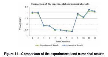
The in situ measurements were taken in a heading ventilated using a LB; the dimensions of the heading and LB are given in Figure 9. The velocities of air at the entrance of the LB, inside the heading, and at the exit of the LB were measured. The air velocities and direction of the air inside the heading were recorded using hot wire and rotating vane digital anemometers and a smoke tube respectively. Access to within 4 m of the face was not allowed, therefore flow rates close to the face were not taken. The same case was simulated in ANSYS Fluent, and a comparison of the results is given in Table XV and Figure 11.
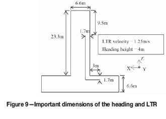
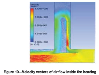
The flow of air inside the heading is shown using velocity vectors in Figure 10. It can be seen that the air entered the LB - wall channel, ventilated the heading, and returned from the downstream side. As expected, since the minimum length of LB required for a LB to wall distance of 1.7 m was not used and a LB to wall distance of 9.5 m was used, very little air exiting the LB actually reached the face. Therefore, LB to wall distance should always be less than 1 m, unless additional engineering solutions are also used.
The measured velocities are given in Table XV along with the coordinates of these points. The bottom right corner of the LTR was considered as (0, 0, 0). Positive and negative signs indicate the direction of air movement. As expected, at the exit of the LB, air velocities were higher close to the LB. The validation study showed that the ANSYS Fluent k-ε realizable model is suitable for studying the ventilation of a heading connected to the LTR.
Conclusions
To address some of the challenges faced underground by supervisory staff installing LB systems in coal mines, a model was developed using CFD. The effect of system variables related to the installation of the LB, LTR velocity, and heading dimensions on the flow rates close to the face of the empty heading (0.5m from the face), were evaluated. The outcome was represented in a user-friendly numerical model to estimate the consolidated effect of all the studied variables, which can be used to estimate the flow rates close to the face of the heading for different configurations of LB, LTR velocities, and heading dimensions. The model can assist ventilation engineers and the supervisory staff to install LBs correctly and quickly, so as to comply with environmental regulations and mine standards. It can also help academia as part of the curriculum for teaching future mining and ventilation engineers how the different variables associated with the LB ventilation system affect the ventilation in an empty heading.
Acknowledgement
The work presented in this paper is part of a PhD research study in the School of Mining Engineering at the University of the Witwatersrand. The authors would like to acknowledge the Wits Mining Institute (WMI), University of the Witwatersrand, for making the Digital Mine facility available for the research, and the financial assistance required to purchase the high-performance PC and the CFD software.
References
Aminossadati, S.M. and Hooman, K. 2008. Numerical simulation of ventilation air flow in underground mine workings. Proceedings of the 12th US/North American Mine Ventilation Symposium, Reno, Nevada, 9-12 June. Wallace, K.G. Jr. (ed.). Society for Mining, Metallurgy, and Exploration, Littleton, CO. pp. 253-259. [ Links ]
ANSYS® Academic Research. 2015. Release 15.0, Help System, ANSYS Fluent Theory Guide. ANSYS, Inc. Chapter 4. [ Links ]
Bise, C.J (ed.). 2013. Modern American Coal Mining: Methods and Applications. Society for Mining, Metallurgy and Exploration, Englewood, Co. [ Links ]
Candra, K.J., Sasmito, A.P., and Sadashiv, M.A. 2014. Dust dispersion and management in underground mining faces. International Journal of Mining Science and Technology, vol. 24, no. 1. pp. 39-44. [ Links ]
Candra, K.J., Sasmito, A.P., and Sadashiv, M.A. 2015. Introduction and evaluation of a novel hybrid brattice for improved dust control in underground mining faces: A computational study. International Journal of Mining Science and Technology, vol. 24, no. 1. pp. 537-543. [ Links ]
Cheremisinoff, N.P. 2014. Dust Explosion and Fire Prevention Handbook: A Guide to Good industry Practices. Wiley-Scrivener, Beverly, MA. [ Links ]
Creedy, D.P. (1996). Methane prediction in collieries. Report COL 303. Safety in Mines Research Advisory Committee (SIMRAC), Johannesburg, June 1996. [ Links ]
Dubinski, J., Krause, E., and Skiba, J. 2011. Global technical and environmental problems connected with the coal mine methane. Proceedings of the 22nd World Mining Congress and Expo 2011, Istanbul, Turkey, 11-16 September. [ Links ]
Feroze, T. and Phillips, H.W. 2015. An initial investigation of room and pillar ventilation using CFD to investigate the effects of last through road velocity. Proceedings of the 24th International Mining Congress and Exhibition of Turkey (IMCET15). Antalya, Turkey, 14-17 April. Chamber of Mining Engineers of Turkey. pp. 970-977. [ Links ]
Goodman, G.V.R. and Pollock, D.E. 2004. Use of a directional spray system design to control respirable dust and face gas concentrations around a continuous mining machine. Journal of Occupational and Environmental Hygiene, vol. 1, no. 12. pp. 806-815. [ Links ]
Hartman, H.L., Mutmansky, J.M., Ramani, R.V., and Wang, Y.J. 2012. Mine Ventilation and Air Conditioning. 3rd edn. Wiley-interscience. [ Links ]
Lihong, Z., Christopher, P., and Yi, Z. 2015. CFD modeling of methane distribution at a continuous miner face with various curtain setback distances. International Journal of Mining Science and Technology, vol. 25, no. 4. pp. 635-640. [ Links ]
Meyer, C.F. 1993. Improving underground ventilation conditions in coal mines. Final Project Report CoL 029a. Safety in Mines Research Advisory Committee (SIMRAC), Johannesburg. November 1993. [ Links ]
Meyer, J.P., le Grange, L.A., and Meyer, C. 1991. The utilisation of air scoops for the improvement of ventilation in a coal mine heading. Mining Science and Technology, vol. 13, no. 1. pp. 17-24. [ Links ]
Petrov, T., Wala, A.M., and Huang, G. 2013. Parametric study of airflow separation phenomenon at face area during deep cut continuous mining, Mining Technology, vol. 122, no. 4. pp. 208-214. [ Links ]
Phillips, H.R. and Brandt, M.P. 1995. Coal mine explosions - risk and remedy. Proceedings of SIMRAC Symposium, Johannesburg, 1 September 1995. Southern African institute of Mining and Metallurgy, Johannesburg. [ Links ]
Phillips, H.R. 2015. Lessons learnt from mine explosions. Proceedings of the Australian Mine Ventilation Conference, Sydney, NSW, 31 August - 2 September 2015. Australasian institute of Mining and Metallurgy, Melbourne. pp.19-28. [ Links ]
Reed, W. and Taylor, C. 2007. Factors affecting the development of mine face ventilation systems in the 20th century. Proceedings of the Society for Mining, Metallurgy and Exploration (SME) Annual Meeting and Exhibit, Denver, Colorado, 25-28 February 2007. [ Links ]
Sasmito, A.P., Birgersson, E.Ly.H., and Mujumdar, A.S. 2013. Some approaches to improve ventilation system in underground coal mines environment - A computational fluid dynamic study. Tunnelling and Underground Space Technology, vol. 34. pp 82-95. [ Links ]
Taylor, C.D., Timko, R.J., Thimons, E. D., and Mal, T. 2005. Using ultrasonic anemometers to evaluate factors affecting face ventilation effectiveness. Proceedings of the 2005 Annual Meeting of the Society for Mining, Metallurgy and Exploration (SME), Salt Lake City, Utah. 28 February- 2 March. [ Links ]
Thimons, E.D., Taylor, C.D., and Zimmer, J.A. 1999. Ventilating the box cut of a two-pass 40ft extended cut. Journal of the Mine Ventilation Society of South Africa, vol. 59, no. 3. pp. 108-115. [ Links ]
Tien, J.C. 1988. Face ventilation during cross-cut development in a room and pillar operation. Proceedings of the 4th US Mine Ventilation Symposium, Berkeley, CA, 20-22 June. Society for Mining, Metallurgy and Exploration, Littleton, Co. pp. 202-208. [ Links ]
Wala, A.M., Vytla, S., Taylor, C.D., and Huang, G. 2007. Mine face ventilation: a comparison of CFD results against benchmark experiments for the CFD code validation. Mining Engineering, vol. 59, no. 10. pp. 49-55. [ Links ]
Wala, A.M., Vytla, S., Huang, G., and Taylor, C.D. 2008. Study on the effects of scrubber operation on the face ventilation. Proceedings of the 12th US/North American Mine Ventilation Symposium, Reno, Nevada, 9-11 June. Wallace, K.G. Jr. (ed.). Society for Mining, Metallurgy, and Exploration, Littleton, Co. pp. 281-286. [ Links ]
Wang, P.F., Feng, T., and Ronghua, L. 2011. Numerical simulation of dust distribution at a fully mechanized face under the isolation effect of air curtain. Mining Science and Technology, vol. 21, no. 1. pp. 65-69. [ Links ]
Paper received Mar. 2016
Revised paper received Nov. 2016

