


Services on Demand
Article
 English (pdf)
 Article in xml format
 Article references
Indicators

Related links
-
 Cited by Google
 -
 Similars in Google
Share

 Permalink
Journal of the Southern African Institute of Mining and Metallurgy
On-line version ISSN 2411-9717
Print version ISSN 2225-6253
J. S. Afr. Inst. Min. Metall. vol.117 n.1 Johannesburg Jan. 2017
http://dx.doi.org/10.17159/2411-9717/2017/v117n1a8
GENERAL PAPERS
The influence of mining sequence and ground support practice on the frequency and severity of rockbursts in seismically active mines of the Sudbury Basin
P. MorissetteI; J. HadjigeorgiouI; A.R. PunkkinenI; D.R. ChinnasaneII; A. Sampson-ForsytheII
ILassonde Institute of Mining, University of Toronto, Canada
IIVale Canada Ltd., Canada
SYNOPSIS
The performance of ground support systems under dynamic loading is typically assessed in a qualitative and subjective manner. As a result, it is difficult to develop an explicit knowledge on the mechanisms of action and interaction of support elements subjected to rockbursts. This paper examines rockbursts that have occurred at Creighton, Copper Cliff, and Coleman mines since 2000, 2004, and 2006, respectively. The mines are located in the Sudbury Basin, in Ontario, Canada. The majority of pertinent information was obtained through on-site field assessments, seismic system records, and numerical elastic stress modelling. Passive monitoring is used to link the evolution of the frequency and severity of rockbursts to the evolution of mining and support practice at the three mine sites. Based on the collected data, ground support elements that enhanced the capacity of support systems to withstand dynamic loads are identified.
Keywords: rockburst, ground support systems, passive monitoring.
Introduction
The selection of appropriate mining methods, extraction sequences, rock mass de-stressing techniques, and ground support systems is of great importance in mitigating the level of rockburst-related risk. In burst-prone conditions, the design of support systems should account for the anticipated dynamic load demand and the capacity of the available support options. Furthermore, an economical design should, implicitly or explicitly, take into consideration the consequences of a rockburst and its impact on worker safety and mine productivity. Stacey (2012) has argued that we have a limited understanding of the mechanisms of rock mass behaviour in seismic conditions. This is compounded by a 'lack of understanding of the mechanisms of action and interaction of support elements under dynamic loads' (Stacey, 2012). Consequently, the design of support systems required to manage dynamic loads is usually based on experience. The assessment of the dynamic performance of ground support systems is typically subjected to qualitative (and sometimes subjective) interpretations from ground control personnel.
Passive monitoring is a useful tool in assessing the performance of ground support systems. Forensic analysis, in the context of rock support in burst-prone ground conditions, is the assessment of the damage to an excavation or its support with the purpose of identifying the cause(s) of failure and/or validating design parameters (Kaiser and Cai, 2013). This information can be used to propose remediation strategies or to design new reinforcement elements (Li, 2010, 2012; Li and Doucet, 2012) or ground support systems. Passive monitoring based on reviews of historical rockburst data, on the other hand, can trace the evolution of mining and support practice at a mine site and further trace their relation to the frequency and severity of rockbursts. This type of analysis, based on observed improvements in managing the consequences of rockbursts, can justify changes in mining strategy and/or support practice.
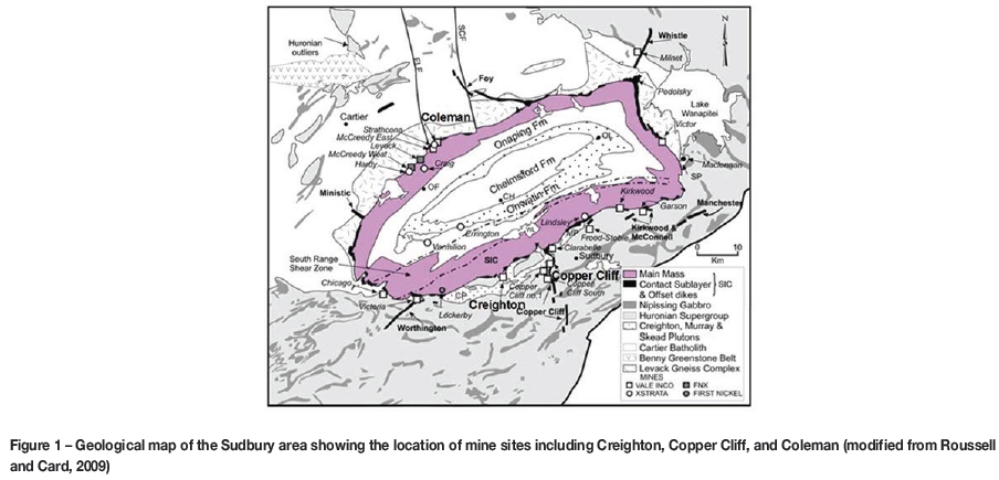
Unusual occurrence reports for groundfalls/rockbursts (MASHA, 2009) were collected at Vale's Creighton, Copper Cliff (formerly Copper Cliff North), and Coleman mines. These mines are located, respectively, within the South Range, Copper Cliff Offset, and North Range of the Sudbury Basin in Ontario, Canada (Figure 1). Each site employs dedicated ground control personnel. This has ensured continuity in the quality of the collected data. Information from on-site assessments was cross-validated with information obtained through seismic monitoring systems, geological mapping layouts, external reports, and site inspections.
A retrievable database was constructed with 183 case studies of ground support damage from Creighton, 35 from Copper Cliff, and 105 from Coleman. This paper reports on lessons learned by monitoring changes in mine design and ground support with references to rockburst case studies from three high-stress underground mines. This is a continuation of previous work by Morissette et al. (2014).
History of rockbursts at Creighton, Copper Cliff, and Coleman mines
Creighton, Copper Cliff, and Coleman mines operate at different depths and are located within several lithological units. The majority of rockburst case studies considered in this analysis were associated with mining of the Deep 400 and 461 orebodies at Creighton, the 100 and 900 orebodies at Copper Cliff, and the Main (MOB) and 153 orebodies at Coleman. These six orebodies are represented on the same scale in order to illustrate variations of size and depth among the three mine sites (Figure 2).
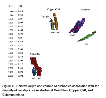
Slot-and-slash and vertical retreat mining (VRM), i.e. variations of open stope mining, are the predominant mining methods at Creighton and Copper Cliff. The Deep 400 and 461 orebodies at Creighton are mined using a top-down/centre-out (or V-shaped) sequence in order to accommodate higher levels of mining-induced stresses and seismicity. Mining at Copper Cliff, on the other hand, progresses using a bottom-up sequence. At Coleman mine, until December 2013, post pillar cut-and-fill was the predominant mining method in the MOB, with open stope mining being used for sill pillar recovery in the upper part of the orebody (MOB1). The mine is currently transitioning from cut-and-fill to open stope mining in the lower MOB (MOB2 and MOB3) for sill pillar recovery. These areas are represented in magenta on the side view of the MOB (Figure 2). Overhand cut-and-fill is the predominant mining method employed in the 'narrow-vein' 153 orebody. Underhand cut-and-fill is used for most of the sill pillar recovery; open stoping accounts for less than 10% of the mining in the 153 orebody.
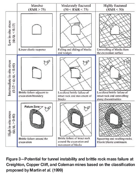
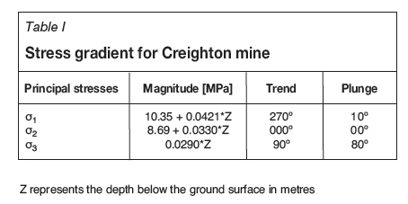
Morissette et al. (2014) have presented a comprehensive review of the geology and rock mass properties at Creighton, Copper Cliff, and Coleman mines. Ranges of rock mass quality and stress conditions typical for the three mines are represented in Figure 3. In this conceptual diagram, the observed conditions suggest the potential for brittle rock mass failure and movement of blocks. The stress gradient for Creighton mine is provided in Table I. Stress gradients at Copper Cliff and Coleman mines are similar to that at Creighton, given the proximity of the mines.
The mine sites were selected for this investigation based on their history of rockbursts and the quality of their seismic data. Creighton mine has operated a calibrated seismic monitoring system for many years. For the purposes of this project, the collection of rockburst data at Creighton covered events from January 2000 to September 2013. At Copper Cliff and Coleman mines, the operation of a calibrated seismic monitoring system began in 2004 and 2006. Consequently, rockburst data from January 2004 and January 2006 to September 2013 was collected and analysed for Copper Cliff and Coleman mines.
From the collected rockburst data, the severity of each rockburst was assessed using visual estimates of the displaced tonnage reported by the ground control personnel at the time. The evolution of the frequency and severity of rockbursts can be represented by the cumulative displaced tonnage over time, given that the complete rockburst history has been collected over the studied time period (Figure 4).
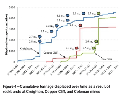
Large-magnitude seismic events (> 2.0 mN) and the associated damage have been much more frequent at Creighton than at Copper Cliff and Coleman. This is reflected by the steady increase in the cumulative displaced tonnage at Creighton (Figure 4). Copper Cliff and Coleman have been occasionally affected by very severe rockbursts that displaced substantial amounts of material. However, at Copper Cliff and Coleman, the rate of displaced tonnage between severe events is relatively low. This distinction in the evolution of the frequency and severity of rockbursts might reflect the influence of the increasingly high-stress conditions faced at Creighton as the mining progressed to greater depths. The trend observed at Creighton mine further suggests a gain of experience in managing high-stress and burst-prone conditions over time. Since 2004, Creighton has experienced the least amount of rock displaced due to rockbursts, despite being the deepest of the three mines and the one that experienced rockbursts the most frequently. In the following sections, the evolution of the frequency and severity of rockbursts at Creighton, Copper Cliff, and Coleman mines is analysed by exploring correlations with the evolution of mining and ground support practice at the three sites.
Evolution of mining and support practice
Creighton mine
The 400 and 461 orebodies (Figure 2) have been mined at Creighton over the time period covered by this study. Most of the ore extraction took place in the deep part of the mine, i.e. below the 6400 level (1950 m). Currently, the majority of economic mineralization has been depleted down to the 7400 level (2255 m) in the Deep 400 orebody and to the 7840 level (2390 m) in the 461 orebody.
Stope design and seismic risk management
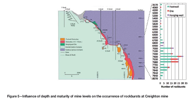
At Creighton mine, the occurrence of rockbursts appears to be influenced by the depth and maturity of mine levels (Figure 5). A noticeable increase in the total number of rockbursts is observed as the mine depth approaches the 7400 level (2255 m). Open stopes varying from 53 to 60 m in height were mined at levels above 2255 m depth in the 400 orebody. Below the 7400 level, the spacing between top and bottom sills was reduced to 40 m in anticipation of higher stress conditions at greater depths and to better delineate the mineable reserves. Since 2005, the majority of stopes were mined below the 7400 level in Creighton Deep. Mining in the 461 orebody began in 2006. Recognizing the unfavourable orientation of the orebody with respect to the major principal stress, reflected by seismic activity in the area over the last few years, the mine employed stopes with a design height of 26 m. Fine-tuning of stope design is an ongoing process at Creighton mine.
The reduction in the stope height at Creighton has likely contributed to preventing an escalation of seismic activity as the mine progressed to greater depths. This is reflected by the evolution of the rate of seismicity, which was assessed from January 2000 to September 2013 using the magnitude-time history analysis technique (Figure 6). This technique is described in detail by Hudyma and Potvin (2010).
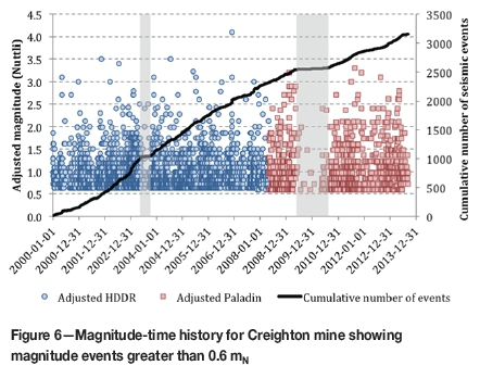
On the magnitude-time history chart, an approximately constant rate of seismicity was observed between two labour interruption periods, which lasted from April to August 2003 and from July 2009 to July 2010. These two periods are highlighted by grey-shaded areas in Figure 6, within which decay of seismic activity is representative of labour interruption. Between these two periods, a slight decrease in the rate of seismicity was noticed starting late 2005, which could be attributed to the mining of smaller stopes in the 400 orebody.
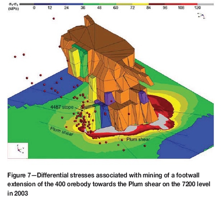
On the other hand, a noticeable increase in the rate of seismicity at Creighton occurred, starting September 2001 and accelerating in September 2002. Seismicity during this period was exacerbated by mining a footwall extension of the 400 orebody between the 7000 and 7200 levels, which generated stress concentrations in the vicinity of the Plum shear zone. This structure is currently amongst the most seismically active of ten major shear zones interpreted within Creighton Deep. Figure 7 illustrates the concentration of seismic events from January to April 2003 in the immediate footwall of the 4487 stope mined in early 2003. These events, of reported magnitude greater than 0.8 mN, coincide with the observed high stress conditions in this area. Differential stresses were assessed using Map3D, a 3D elastic boundary element numerical package.
The magnitude-time history analysis for Creighton included data from the two macroseismic monitoring systems employed at the mine: the HDDR from 2000 to May 2008 and the Paladin starting May 2008. The magnitudes recorded on site were cross-validated using the large-magnitude seismic events captured by the Geological Survey of Canada (GSC) (Figure 8). The Nuttli magnitudes of those large events were obtained through the National Earthquake Database (National Resources Canada, 2015).
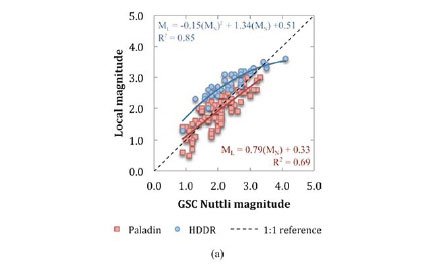
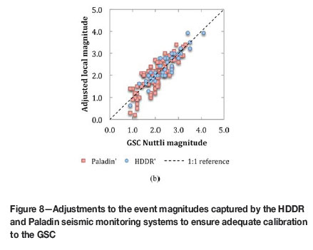
A discrepancy was observed between the HDDR and Paladin raw magnitude data (Figure 8a). To enable comparison with the Nuttli magnitude scale employed by the GSC, the magnitudes recorded by the HDDR and Paladin systems were fitted using polynomial regression and further adjusted accordingly. The objective was to centre the two sets of magnitude data on the 1:1 reference line, using the parameters from the regression equations (Figure 8b). This validation process facilitated the comparison of magnitude data between the two macroseismic systems employed at the mine over time. The adjustment was validated further using the magnitude-time history chart (Figure 6) to ensure that no significant variation in the rate of seismicity could be detected near May 2008 that could be attributed to the change of seismic monitoring system.
The magnitude-time history analysis demonstrated that, although mining has influenced seismicity at Creighton mine, the seismic hazard has been adequately managed. This was reflected by the relatively constant rate of mining-induced seismicity over time, despite mining at greater depth and within the unfavourable stress conditions associated with the 461 orebody. The magnitude-time history analysis corroborated the engineering decision of adjusting the stope design in anticipation of higher stress environments in the 400 and 461 orebodies. This case study exemplified that in deep underground mines, the role of engineering is not to eliminate seismicity, but to manage it.
Enhanced ground support systems
Ground support practices at Creighton mine evolved as mining progressed to greater depths. The mine began to install modified cone bolts (MCBs) in conjunction with 0/0 gauge straps as part of its 'enhanced' ground support system in December 2004. In February 2005, a 2.0 m long, 46 mm diameter friction set was introduced as part of the wall support system. This bolt replaced the 1.7 m long, 35 mm diameter friction set and its predecessor, the 39 mm version (Punkkinen and Yao, 2007). As of November 2006, the minimum ground support standard consisted of a diamond pattern of 2.4 m long resin rebars and mechanical bolts in the back and 2.0 m long 46 mm friction sets in the walls. Mechanical bolts and rebars in the back were both installed on a 1.2 m x 1.5 m diamond pattern. Friction sets were the only reinforcement elements employed in the walls and were installed on a 1.2 m χ 0.8 m pattern. Reinforcement elements were installed in conjunction with no. 4 gauge galvanized welded wire mesh down to floor level. Shotcrete was frequently applied over the bolts and mesh to provide further surface support. In areas of the mine susceptible to rockbursts, the support standard was enhanced by adding 2.4 m long MCBs and 0/0 gauge straps (Malek et al. 2008) (Figure 9a).
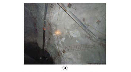
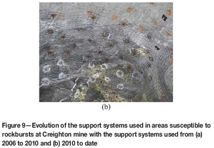
The use of mechanical bolts at Creighton mine was discontinued in June 2010 in response to corrosion issues and inadequate performance under dynamic loads. In September 2010, MCB33s (modified cone bolts for installation into 33 mm diameter boreholes) became part of the primary support system below the 7810 level in areas where enhanced support is prescribed. MCB33s are installed along with resin rebars on a dense, 1.2 m x 1.0 m, diamond pattern. 0/0 gauge mesh squares (0.3 m) are installed in order to enhance the connection between the no. 4 gauge screen and the reinforcement elements and to protect the surface support from being damaged by the cutting action of the plates (Figure 9b). The support system in the walls was enhanced further with the addition of MCBs and 0/0 gauge squares in areas susceptible to rockbursts. Shotcrete is no longer part of the minimum support standard as it could not effectively manage higher dynamic loads and often cracked and spalled, requiring frequent rehabilitation. Shotcrete is, however, still used regularly on the lower walls and pillar noses of bottom sills to prevent damage by production equipment or to rehabilitate damaged mine openings. It is also used as a stiff support element beneath mesh installed with dynamic support for permanent infrastructure such as refuge stations or mine power stations, at stope bottom sills as brow control for the production phase, and in backfill development beneath backfill stopes. Shotcrete is also used for all stope fill barricades and in wall or post construction to reduce span in wide openings. Large-diameter inflatable bolts are often used in rehabilitation and in areas where the presence of highly fractured rock mass does not facilitate the use of resin-grouted bolts.
Ground control personnel at Creighton mine monitored the performance of individual reinforcement and surface support elements over time in order to identify limitations in the employed support systems. Following observations of rebar failures in the threaded portion of the tendon through 2011 and 2012, the rebar nut was modified with a spherical seat to accommodate a dome washer plate (Vale, 2012). The dome assembly provides for effective installation of the rebar without risking damage to the threaded portion of the bolt when installed in unavoidable angular orientations.
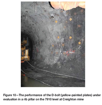
For several years, the mine successfully employed 46 mm post galvanized friction set bolts (FS-46) with a crimp design bushing. As the production front adversely loaded pillars with the progression of mining to greater depths, crimp failures began to occur in 2011-2012. These repeated failures suggested the limitation of this bolt configuration for the high-stress bottom sills of the 461 orebody and motivated the adoption of a welded-ring design. Pull tests conducted on site demonstrated that the capacity of the ring was enhanced from 10-11 t to 17-18 t with the welded design (Vale, 2012). Furthermore, as part of continuous efforts to explore new support strategies, the mine was, as of September 2013, investigating the performance of the D-bolt on 7910 level (Figure 10).
Cable bolting of large excavations
Cable bolting at Creighton Deep is performed systematically and in a timely manner, prior to the installation of mine services, in all intersections where development headings are larger than 5 m x 5 m. In practice, the mine cable-bolts excavations with a span greater than 7.3 m, which corresponds to three times the length of primary reinforcement elements, as per the support standard reviewed in June 2005. Cable bolts are also employed where geological structures, high walls, dynamic loading conditions, or ground conditions warrant, at the request of the ground control department (Vale 2012). Double 16 mm (5/8 inch) plated cables are typically installed on a 2.1 m χ 2.1 m pattern. For excavation spans smaller than 12 m, the pair of cement-grouted cables installed in 5 cm diameter drill-holes consists of a 6.4 m long bulged cable and a 5.5 m long plain strand cable.
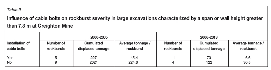
A systematic review of rockburst occurrences at Creighton mine indicated that in large excavations (span or wall height > 7.3 m), the installation of cable bolts tended to enhance the overall performance of the support system (Table II). This was reflected by the increased severity of damage, represented by the reported displaced tonnage, in areas where cable bolts were not part of the support system. The advantage of using cable bolts can be attributed to their capacity of tying the support back to stable ground due to the additional length. It may, furthermore, be attributed to the softer behaviour of cable bolts as opposed to other reinforcement elements. Bulged cables provide an immediate stiff load response, which is desirable in highly fractured ground, whereas the plain strand cables are capable of withstanding moderate dynamic loading conditions (Hutchinson and Diederichs, 1996).
Discussion
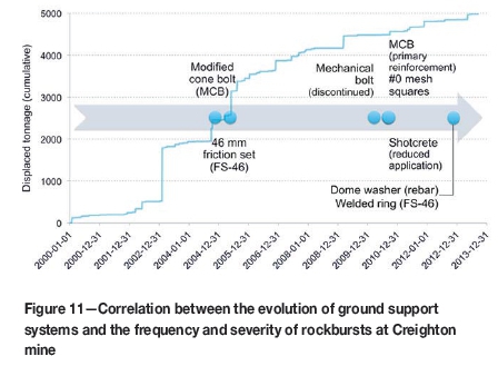
The majority of changes in stope dimensions and support practice at Creighton were initiated between 2004 and 2005. Recent modifications to the enhanced support system became part of the standard in 2010. The evolution of the frequency and severity of rockbursts at Creighton, depicted in Figure 4, shows strong correlations with these changes. These correlations are emphasized in Figure 11. As ground support practice was modified for deep and high-stress conditions, a significant decline in the rate of rockburst damage was observed.
Copper Cliff mine
Copper Cliff and Coleman mines, although not as deep and seismically active as Creighton, have encountered very severe, although sporadic, rockbursts since 2004 and 2006 respectvely. At Copper Cliff Mine, the most severe events occurred on 25 March and 11 September 2008 (Figure 4).
25 March 2008 rockburst
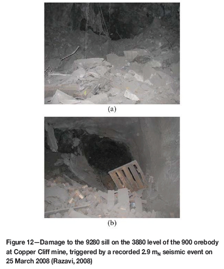
On 25 March 2008, a recorded 2.9 mN seismic event generated over 635 t of displaced material on the 3880 level of the 900 orebody. The seismic source was located in the vicinity of the Trap Dyke, one of the most prominent seismically active geological structures at the mine (Hudyma and Brummer, 2007), which is located between the 100 and 900 orebodies (Figure 2). Damage to the installed ground support system occurred within 31 to 39 m from the epicentre of the 2.9 mN seismic event. The damage areas at the time were supported using a combination of 1.8 m long mechanical bolts and rebars in the back and 1.7 m long 39 mm friction sets in the walls. The surface support consisted of no. 6 welded wire mesh overlapped with plain shotcrete. In intersections, 6.4 m long cable bolts were installed on a 2.1 x 2.1 m pattern. Photographs of the most severely damaged areas revealed a complete collapse of the surface support and failure of several friction set and mechanical bolts, which were found in the muck pile (Figure 12).
11 September 2008 rockburst
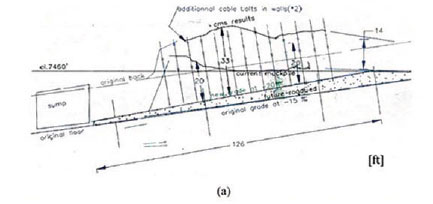
The 11 September 2008 rockburst was the result of a series of 10 seismic events that ranged from 1.2 to 3.8 mN and occurred from 07:21 to 08:06 (Yao et al., 2009). The series of events was triggered by the crown blast of the 94561 stope in the upper 100 orebody (3050 to 3200 level) at 07:21. The seismic events resulted in damage to mine excavations from 2700 level down to 3710 level. The distance between the epicenter of the 3.8 mN seismic event and the damage ranged from 40 m to over 200 m. The rockburst displaced an estimated total of 2100 t as the most prominent damage mechanism was interpreted as seismic shakedown due to the 3.8 mN event (Suorineni and Vasak, 2008). The most severe damage, estimated at 1360 t displaced, occurred in the mine ramp between the 3500 and 3550 levels (Figure 13a). This damage area was located 73 m away from the 3.8 mN event and was characterized by a span of 4.9 m. The reported depth of failure in the ramp extended far beyond the primary reinforcement, varying from 3 m to 6 m. The other three most severely damaged areas comprised the section of the ramp between the 3000 and 3050 levels (Figure 13b), the return air drift on 3500 level, and the 3710 level footwall drift. The damage to mine excavations and support systems in these three areas was localized at the intersection with the Trap Dyke and was estimated at 181, 363, and 91 t respectively.
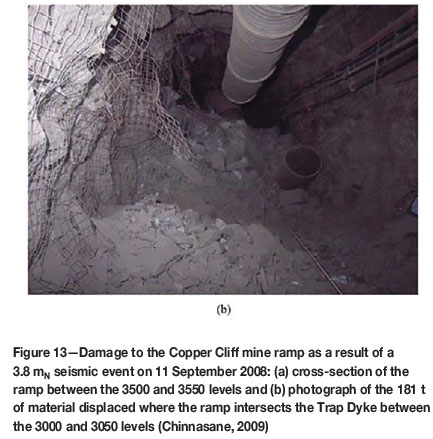
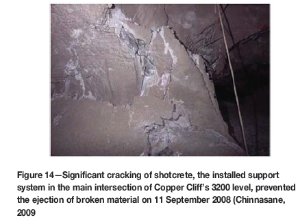
The ramp, as well as the majority of the excavations affected by the 11 September 2008 rockburst, was supported using a diamond pattern of 1.8 m long mechanical bolts and rebars in the back and 1.8 m long mechanical bolts in the walls (Chinnasane, 2009). The surface support in the damage locations generally consisted of no. 6 welded wire mesh. Plain shotcrete, however, was applied over the mesh on the 3200 (Figure 14) and 3710 levels. Although the damage was typically less severe in areas where shotcrete was applied, the support system generally did not perform satisfactorily under seismic shaking (Suorineni and Vasak, 2008).
Adjustments to support practice and mining sequence at Copper Cliff mine
The significant levels of rehabilitation required after the 11 September 2008 rockburst prompted a revision of the support practices at Copper Cliff mine. Since 2008, many of the support elements successfully used at Creighton mine have been introduced on the site. At the present time, the minimum ground support standard employed at Copper Cliff consists of no. 4 welded wire mesh installed with 1.8 or 2.4 m long resin rebars in the back, depending on the size of the opening, and 1.7 m long 39 mm friction sets in the walls. The reinforcement is installed on a 1.2 x 1.5 m diamond pattern. When burst-prone conditions were anticipated, the 39 mm friction sets were replaced by 46 mm friction sets in the design. Shotcrete was applied over the mesh and 2.4 m long MCBs were installed in conjunction with 0/0 gauge straps on a 1.2 χ 1.8 m pattern (Chinnasane et al., 2012). Since 2013, Copper Cliff mine has moved towards the use of 2.4 m long D-bolts on a 1.2 m χ 1.5 m diamond pattern in the back and shoulders, and 46 mm friction sets in the walls as part of a first-pass dynamic ground support strategy. Second-pass wall support includes 2.4 m long D-bolts on a 1.5 m χ 1.5 m pattern in conjunction with three 0/0 gauge straps installed horizontally at 1.5 m spacing.
Since 2008, the mining sequence has been adjusted by postponing the extraction of the 900 orebody in order to minimize the seismic hazard associated with mining on both sides of the Trap Dyke, (Vale, 2010). Finally, preconditioning of rock masses became standard practice when developing in the vicinity of the Trap Dyke.
From a ground control point of view, the use of de-stress blasting in development headings and adjustments to the mining sequence and ground support systems have been beneficial to Copper Cliff mine. Since the 11 September 2008 events, only eight rockbursts have occurred at the mine. These rockbursts resulted in 91 t of cumulated displaced rock material from nine mine locations. Damage to the installed support system occurred in only four of these locations. In the remaining locations, the broken material was displaced from unsupported areas such as lower walls or development faces. Since 2008, the mine has been able to significantly reduce the rockburst hazard associated with production blasting. In effect, six of the eight rockbursts since 2008 were associated with development activities, and three of them occurred while progressing through the Trap Dyke.
Coleman mine
At Coleman mine, the most severe series of rockbursts occurred from September 2010 to April 2011 (Figure 4). The three rockbursts that were the most damaging to the support are reviewed in this section.
24 September2010 rockburst
On 24 September 2010, a 2.6 mN seismic event displaced approximately 181 t from two accesses to Block 2 of the 153 orebody on the 4700 mine level (Figure 15a). The seismic event was located in the footwall of the 153 orebody, approximately 55 m from the resulting damage. About 172 t were displaced from the back of the 11/12 access (5.5 m span) near the intersection, at the location of a narrow bornite stringer (Razavi, 2010).
The 2.4 m long rebars and mechanical bolts installed in the backs of the Cut 11/12 and 9/10 accesses were heavily corroded (Figure 15b, c). Consequently, the bolts were not effective in holding the damaged ground. The no. 6 gauge mesh-reinforced shotcrete was also severely damaged during the event. Cable bolts installed in the backs of the intersections were, however, very effective in preventing further damage from extending outside of the accesses.
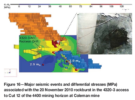
20 November 2010 rockburst
An estimated 360 to 450 t was displaced from the 4320-3 access on the 4400 level of the narrow-vein 153 orebody on 20 November 2010. A development blast had been fired at 05:07 that day in the 4320-3-access footwall drift, triggering a recorded 2.9 mN seismic event which plotted in the vicinity of the blast. The 2.9 mN event occurred at 05:20 and was followed two minutes later by a 2.0 mN event which plotted in the vicinity of the ore contact. The succession of events therefore suggested that the 2.9 mN event triggered a slip along the ore contact. The damage was located in the access to Cut 12, at the intersection of the ore/footwall contact (5.8 m span), about 45 m southeast of the blast. Most of the broken material was displaced from the back of the excavation and extended up to 3 m deep, beyond the 2.4 m length of the installed resin-grouted rebars.
Numerical elastic stress modelling indicated that the footwall drift where the development blast had been fired was likely undergoing stress changes due to mining of the sill pillar between the 4400 and 4250 mining horizons (Figure 16). Greater stress concentrations were located in the immediate footwall of the 153 orebody at the Cut 12 elevation. It is therefore possible that, prior to the 2.9 and 2.0 mN seismic events, the rock mass at the damage location was already highly fractured. The mining-induced seismicity observed in the morning of 20 November 2010 would have, consequently, contributed in shaking the broken material and resulted in the load-bearing capacity of the installed support system being exceeded. A rehabilitation plan released after the event requested the installation of MCBs or Yielding Swellex in conjunction with 0/0 gauge straps, as well as a second pass of cable bolts in the back of the Cut 12 intersection (Sampson-Forsythe, 2010).
6 April 2011 rockburst
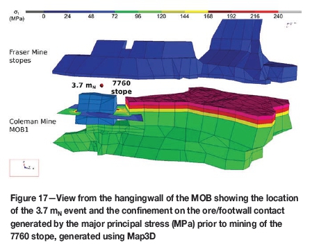
Mining of the 7760 secondary pillar in the narrow west end of the MOB1 generated extensive seismic activity in late 2010 and early 2011. The first and final (crown) blasts in this stope were fired on 17 December 2010 and 4 April 2011. During this period, five seismic events were recorded with a magnitude greater than 2.0 mN. Rockbursts occurred on the 3511 top sill level, in the vicinity of the 7760 stope, on 26 January, 18 March, and 6 April. These rockbursts were associated with 2.9, 3.4, and 3.7 mN seismic events, as reported by the GSC. The 6 April 2011 rockburst was the most severe of the three events, resulting in a total of about 2360 t displaced from six stope accesses on the top sill level, 17 to 50 m away from the epicentre of the 3.7 mN event. Given the orientation of the major principal stress, roughly perpendicular to the trend of the MOB in this area, high stress conditions were observed within the 7760 stope and generated high confinement on the ore/footwall contact (Figure 17). It is our interpretation that mining of the 7760 stope contributed in 'unclamping' this discontinuity, which in turn resulted in the occurrence of large-magnitude seismic events.
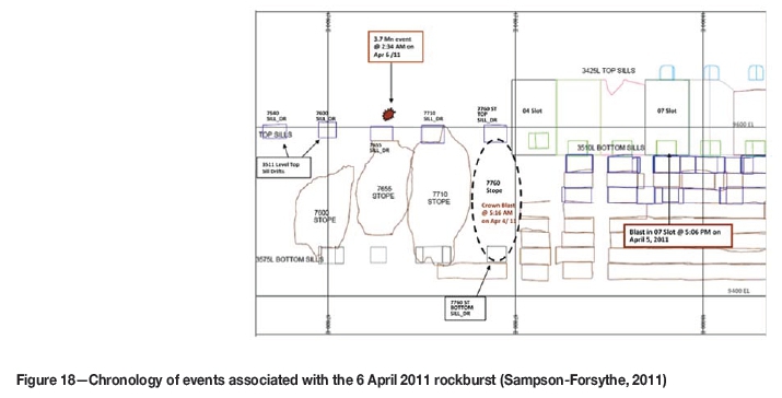
The 3.7 mN event plotted at the footwall contact of the MOB and occurred at 02:34 on 6 April 2010, 45 hours after the crown blast. It had been reported that the blast did not break through the crown and that a 10 m thick pillar remained. Consequently, it was suspected that the footwall of the 7760 stope was still under high stress at that time. At 17:06 on 5 April, in the 07 slot, a development blast was fired at the ore/footwall contact, about 60 m northeast of the 7760 stope. This development blast most likely triggered the fault-slip event along the ore/footwall contact, which resulted in a 3.7 mN magnitude event. Subsequently, seismicity migrated toward the west abutment of MOB1, indicating that stresses had been diverted from the 7760 stope area (Sampson-Forsythe, 2011). A chronology of the events is presented in Figure 18.
The support system installed in the damaged accesses at the time of the event consisted primarily of 2.4 m and 1.8 m long resin rebars in the backs and walls, respectively, and no. 6 gauge welded wire mesh. The excavation span in the damage locations varied from 7.0 to 7.6 m. In the 7760 access, however, the support was enhanced with the installation of 2.4 m MCBs and 0/0 gauge straps. The majority of the damage extended beyond the length of the reinforcement. Following the event, the installation of enhanced support was prescribed in the west abutment of the MOB1 in order to manage high stress levels and promote the stability of mine openings in this area, as mining of the sill pillar progresses to the west (Sampson-Forsythe, 2011).
Adjustments to support practice at Coleman mine
Since the 6 April 2011 3.7 mN event, there has been a significant reduction in excavation damage due to rockbursts at Coleman mine (Figure 4). This can be attributed partly to the introduction of a yielding support system. The current practice in burst-prone ground conditions consists of enhancing the primary support system (composed predominantly of resin rebars and no. 6 welded wire mesh) using 0/0 gauge straps and either Yielding Super Swellex or D-bolts. Yielding Super Swellex is usually preferred at Coleman due to its ease of installation in areas where (a) the ground is significantly fractured in the immediate vicinity of excavations and seismic shakedown is anticipated, (b) older excavations have previously experienced large magnitude seismic events, and (c) excavations have a shorter service life. The D-bolt and 0/0 gauge straps are used in newer development headings and are installed immediately after the primary support. The demonstrated performance of the support systems at Coleman from April 2011 to September 2013 corroborates the adjustments made to the support practice during this period (Figure 4).
Discussion
Three mines, three stories
The evolution of the frequency and severity of rockbursts has been reviewed for Creighton, Copper Cliff, and Coleman mines. Creighton mine provides an excellent example of the evolution of ground support systems as mining progressed to higher stress environments. Correlations were identified between the improved performance in dynamic loading conditions at Creighton and changes in mining and ground support practice since 2005. Significant mining-induced seismicity is a more recent occurrence at Copper Cliff and Coleman mines. This is attributed to the maturity of the mines and the mining of narrow multi-sill pillars at Coleman and sill pillars of the 100/900 orebodies at Copper Cliff. The high-severity rockbursts of 2008 at Copper Cliff and 20102011 at Coleman necessitated an immediate intervention in the ground support systems as opposed to the continuous evolution at Creighton. Consequently, lessons from Creighton Mine provided a useful template.
Designing mining sequences under high-stress conditions requires attention to both ground control and production constraints. The 11 September 2008 rockburst at Copper Cliff and the 6 April 2011 rockburst at Coleman were potentially attributable to issues related to the extraction sequence. Mining both the 900 and 100 orebodies, on each side of the Trap Dyke, contributed to the 3.8 mN seismic event at Copper Cliff. At Coleman, the 7760 stope was used as a secondary pillar in order to allow the mining of open stopes west of the post pillar cut-and-fill area. When mining of the 7760 stope began, the footwall contact was clamped due to the high major principal stress. Severe mining-induced seismic events occurred as the stress along the contact was released due to production blasting. It is recognized that mining in burst-prone ground conditions requires a trade-off between production requirements and ground control.
Typical causes of ground support failure under dynamic loading conditions
The review of support performance over time has identified typical causes of ground support failure under dynamic loading conditions, which have been assigned to three phases of the ground support cycle: the design; the installation, quality control, and quality assurance processes; and the performance under dynamic loads (Figure 19).
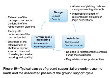
In the design phase, the selection of yielding reinforcement elements in conjunction with strong connecting elements and the systematic installation of cable bolts in large excavations improves the performance of the ground support systems. The rate of rockburst severity, as represented in Figure 4, was significantly reduced following the introduction of yielding reinforcement elements at the three mines. Since 2005, part of Creighton mine's success in managing the ejection of large volumes of rock was due to the systematic approach of cable-bolting large excavations.
Installation and quality control reviews at Creighton identified cases of premature damage to certain reinforcement elements. This led the mine to implement a series of measures to minimize early damage to the threaded portion of rebars and to the rings of friction sets. These measures were implemented at all Vale mines in the Sudbury area. Furthermore, corrosion was identified as an important factor leading to the degradation of ground support systems, as it severely affected the support performance during the 24 September 2010 rockburst at Coleman mine.
Through rockburst case studies from Copper Cliff and Coleman mines, it was demonstrated that ground support systems cannot manage dynamic loads when the depth of the damage zone exceeds the length of the installed reinforcement elements. Furthermore, some reinforcement elements, such as mechanical bolts, have been found to be inadequate in managing dynamic loads at Creighton, Copper Cliff, and Coleman mines.
Finally, based on the experience at Creighton mine, it would appear that the effectiveness of shotcrete is diminished beyond a certain threshold of loading. Shotcrete performs poorly under dynamic loads due to its high stiffness and fundamentally brittle behaviour. Shotcrete loosening has become a major issue in high-stress mines under both static and dynamic loads (Counter, 2012). Nevertheless, shotcrete is capable of keeping the ground tight by limiting rock mass dilation, as opposed to mesh, which is passive. As a result, shotcrete is capable, to a certain extent, of preserving a laminated beam and maintaining confinement around reinforcement elements (Simser, 2012). The 3.8 mN seismic event at Copper Cliff mine indicated that the use of shotcrete could be effective in preventing large seismic shakedowns. Recently, some high-stress mines have adopted a mesh-over-shotcrete approach in order to better manage dynamic loads (Punkkinen and Mamidi, 2010; Counter, 2012; Simser, 2012). Such an approach allows the shotcrete to keep the ground tight, whereas the mesh can better absorb high levels of kinetic energy and accommodate larger deformations. The topic of shotcrete requires more attention in order to define its use as part of support systems designed for managing dynamic loads.
Conclusions
The paper has reported on lessons learned over time at Creighton, Copper Cliff, and Coleman mines in managing dynamic loading conditions. By considering the evolution of the frequency and severity of rockbursts, the justification for introducing new support technologies, identifying limitations in the employed support designs, and managing the mining process over time were demonstrated in quantifiable terms. Empirical experience, developed through the analysis of rockburst case studies, has provided valuable elements of design information that have contributed to the implementation of successful support strategies at Creighton, Copper Cliff, and Coleman over time. The lessons learned in managing dynamic loading conditions were transferable in these cases from one mine site to another.
Acknowledgements
The authors would like to acknowledge Vale for financial support and permission to publish this paper. Ground control personnel at Creighton, Copper Cliff, and Coleman mines are thanked for their technical assistance and their contributions to this paper.
References
Chinnasane, D.R. 2009. Unusual occurrence report for rockburst NM-117. Vale, Copper Cliff, ON. [ Links ]
Chinnasane, D.R., Yao, M., Landry, D., and Paradis-Sokoloski, P. 2012. Performance of dynamic support system in highly burst-prone ground conditions at Vale's Copper Cliff Mine-a case study. Proceedings of the VI International Seminar on Deep and High Stress Mining. Potvin Y. (ed.). Australian Centre for Geomechanics, Perth, WA. pp. 57-69. [ Links ]
Counter, D.B. 2012. Support system evolution at Kidd mine. Proceedings of the Dynamic Ground Support Applications Symposium, Sudbury, ON, 13 September 2012. Workplace Safety North, North Bay. http://www.workplacesafetynorth.ca/sites/default/files/ Support%2520System%2520Evolution%2520at%2520Kidd%2520Mine.pdf [Accessed 4 August 2014]. [ Links ]
Doucet, C. and Voyzelle, B. 2012. Technical information data sheets. CanmetMINING, Ottawa, ON. 37 pp. [ Links ]
Hudyma, M. and Brummer, R. 2007. Copper Cliff North Mine seismicity review: 2004-2006-first draft. Itasca Consulting Canada, Sudbury, ON. [ Links ]
Hudyma, M. and Potvin, Y.H. 2010. An engineering approach to seismic risk management in hardrock mines. Rock Mechanics and Rock Engineering, vol. 43. pp. 891-906. [ Links ]
Hutchinson, D.J. and Diedrichs, M.S. 1996. Cablebolting in underground mines. BiTech Publishers, Richmond, BC. [ Links ]
Kaiser, P.K. and Cai, M. 2013. Critical review of design principles for rock support in burst-prone ground-time to rethink. Proceedings of the VII International Symposium on Ground Support in Mining and Underground Construction. Potvin, Y. and Brady, B. (eds). Australian Centre for Geomechanics, Perth, WA. pp. 3-38. [ Links ]
Li, C.C. 2010. Field observations of rock bolts in high stress rock masses. Rock Mechanics and Rock Engineering, vol. 43. pp. 491-496. [ Links ]
Li, C.C. 2012. Performance of D-bolts under static loading. Rock Mechanics and Rock Engineering, vol. 45. pp. 183-192. [ Links ]
Li, C.C. and Doucet, C. 2012. Performance of D-Bolts under dynamic loading, Rock Mechanics and Rock Engineering, vol. 45, pp. 193-204. [ Links ]
Malek, F., Trifu, C., Suorineni, F.T., Espley, S., anD Yao, M. Management of high stress and seismicity at Vale inco Creighton Mine. Proceedings of the XLII US Rock Mechanics Symposium, San Francisco, CA, 29 June-2 July 2008. American Rock Mechanics Association. pp. 1069-1076. [ Links ]
Mansour Mining. (2015). Product catalogue. http://mansourmining.com/Downloads/MMTI%20Product%20Catalogue%20V2.pdf [Accessed 17 Apr. 2015]. [ Links ]
Martin, C.D., Kaiser, P.K., anD McCreath, D.R. 1999. Hoek-Brown parameters for predicting the depth of brittle failure around tunnels. Canadian Geotechnical Journal, vol. 36, no. 1. pp. 136-151. [ Links ]
Mines and Aggregates Safety and Health AssociATion (MASHA). 2009. Technical report-unusual occurrence report for groundfall/rockburst. MASHA, North Bay, ON. [ Links ]
Morissette, P., Hadjigeorgiou, J., and Thibodeau, D. 2014. Investigating the dynamic-load demand on support systems using passive monitoring data. International Journal of Rock Mechanics and Mining Sciences, vol. 67. pp. 115-126. [ Links ]
Map3D (Version 62). Mine Modelling Pty Ltd, Mt. Eliza, Vic. [ Links ]
Natural Resouces Canada. 2015. National earthquake database. http://www.earthquakescanada.nrcan.gc.ca/stndon/NEDB-BNDS/index-eng.php [Accessed 8 Apr. 2015]. [ Links ]
Ortlepp, W.D. and Stacey, T.R. 1998. Testing of tunnel support: Dynamic load testing of rockbolt elements to provide data for safer support design. Report no. GAP 423. Safety in Mines Research Advisory Committee, Johannesburg, South Africa. 43 pp. [ Links ]
Player, J.R., Thompson, A.G., and Villaescusa, E. 2008. Dynamic testing of reinforcement systems. Proceedings of the Sixth International Symposium on Ground Support in Mining and Civil Engineering Construction, Cape Town, South Africa. Stacey, T.R. and Malan, D.F. (eds). Southern African Institute of Mining and Metallurgy, Johannesburg. pp. 597-622. [ Links ]
Punkkinen, A.R. ANd Yao, M. Change of ground support system and mining practice in the Deep at Creighton Mine. Proceedings of the CIM Conference and Exhibition-Montreal 2007, Montreal, QC. 2007. Canadian Institute of Mining, Metallurgy and Petroleum, Montreal. [ Links ]
Punkkinen, A.R. and Mamidi, N.R. 2010. Effective ground support system design to manage seismic hazard in a high stress diminishing pillar at a Vale mine. Proceedings of the Fifth International Seminar on Deep and High Stress Mining. Potvin, Y. and van Sint Jan, M. (eds). Australian Centre for Geomechanics, Perth, WA. pp. 367-381. [ Links ]
Razavi, M. 2008. Unusual occurrence report for rockburst NM-115. Vale, Copper Cliff, ON. [ Links ]
Razavi, M. 2010. ME-149 rockburst at Coleman mine. Vale, Levack, ON. [ Links ]
Roussell, D.H. and Card, K.D. 2009. Sudbury area geology and mineral deposits. A Field Guide to the Geology of Sudbury, Ontario. Roussell, D.H. and Brown, G.H. (eds.). Open File Report 6243. Ontario Geological Survey. pp. 1-6. [ Links ]
Sampson-Forsythe, A. 2010. Unusual occurrence report for rockburst ME-152. Vale, Levack, ON. [ Links ]
Sampson-Forsythe, A. 2011. Unusual occurrence report for rockburst ME-156. Vale, Levack, ON. [ Links ]
Simser, B. 2012. Ground support in 'deep' underground mines. Proceedings of the Dynamic Ground Support Applications Symposium, Sudbury, ON, 13 September 2012. Workplace Safety North, North Bay. http://www.workplacesafetynorth.ca/sites/default/files/Ground%2520Support%2520in %2520Deep%2520underground%2520Mines.pdf [Accessed 4 Aug. 2014] [ Links ]
Stacey, T.R. 2012. Support of excavations subjected to dynamic (rockburst) loading. Proceedings of the XIII SRM International Congress on Rock Mechanics, Beijing. Qian, Q. and Zhou, Y. (eds). International Society for Rock Mechanics. pp. 137-145. [ Links ]
Suorineni, F.T. and Vasak, P. 2008. Expert opinion report on North Mine seismic events of September 11th 2008. Mirarco, Sudbury, ON. [ Links ]
Vale. 2010. Mining methods. Copper Cliff Mine - 2010 Mine Design Package. Chinnasane, D.R. (ed.). Vale, Sudbury, ON. [ Links ]
Vale. 2012. Ground support. Plant 17 Creighton Mine - Mine Design Package 2012 Update. Punkkinen, A. (ed). Vale. Sudbury, ON. [ Links ]
Yao, M., Chinnasane, D.R., and Harding, D. 2009. Mitigation plans for mining in highly burst-prone ground conditions at Vale Inco Copper Cliff North Mine. Proceedings of the 3rd CANUS Rock Mechanics Symposium. Diederichs M. and Grasselli, G. (eds). Canadian Rock Mechanics Association, Toronto, ON. [ Links ]
Paper received Jan. 2015
Revised paper Received June.. 2016

