


Services on Demand
Article
 English (pdf)
 Article in xml format
 Article references
Indicators

Related links
-
 Cited by Google
 -
 Similars in Google
Share

 Permalink
Journal of the Southern African Institute of Mining and Metallurgy
On-line version ISSN 2411-9717
Print version ISSN 2225-6253
J. S. Afr. Inst. Min. Metall. vol.116 n.11 Johannesburg Nov. 2016
http://dx.doi.org/10.17159/2411-9717/2016/v116n11a9
WITS SPECIAL EDITION - VOLUME I
A step towards combating rockburst damage by using sacrificial support
A. MudauI; R.A. GovenderII; T.R. StaceyI
ISchool of Mining Engineering University of the Witwatersrand, Johannesburg, South Africa
IIBlast Impact and Survivability Research Unit (BISRU), Department of Mechanical Engineering, University of Cape Town, Capetown, South Africa
SYNOPSIS
Rockbursts continue to be a major contributor to mine accidents and cause of damage to mine excavations, particularly at great depth. The problem of rockbursts has also escalated in civil engineering tunnels driven at depth, due to high levels of in situ stress at such depths. Attempts have been made in the past to mitigate the impact of rockbursts, with rock support remaining the ultimate method for providing stability in rockbursting environments. However, records show that, on many occasions, conventional support elements such as rockbolts, wire mesh, shotcrete, and lacing fail to withstand severe rockburst events.
Recently, a support method termed 'sacrificial' support was proposed as a potential additional method to prevent rockburst damage, based on observations made after rockburst events in a mine. The philosophy behind a sacrificial support system is that, under dynamic loading conditions, support in the form of a liner must fail; leaving behind, undamaged, what was previously supported rock mass. The sacrificial support concept reported herein is applicable in situations where the source (i.e. seismic event) of the rockburst is located remote from where rockburst damage is likely to occur.
Spalling tests based on the split Hopkinson pressure bar (SHPB) technique were conducted to study some aspects of dynamic rock fracturing in tension at high strain rates and the role a sacrificial layer plays in combating dynamic rock failure. A single Hopkinson pressure bar, with a long cylindrical intact rock specimen attached at the bar free end, was impacted by a striker on the opposite free end in order to generate a dynamic stress pulse responsible for spall failure upon reflection from the specimen free end. Different liners and liner combinations were then introduced at the specimen free end as support. Such a simple, yet robust, experimental set-up allowed the potential benefits and failure mechanisms associated with sacrificial support under dynamic loading to be demonstrated and compared with 'sacrificial support' behaviour observed in real rockburst events in a mine. Analysis of the results revealed that varying liner thickness and mechanical impedance between rock and support liner play a significant role in limiting rockburst damage.
Keywords: rockburst, seismic waves, sacrificial layer, Hopkinson pressure bar.
Introduction
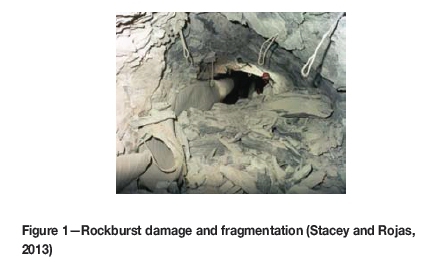
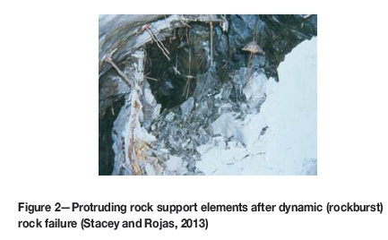
The trend of extracting mineral deposits to their lowest payable grade has characterized mining in most parts of the world for several decades. This is due to pressure to meet the expanding demand for mineral commodities in the world market. Mining operations in major mining countries such as South Africa, Canada, and Australia have already gone beyond 4 km, 3 km, and 2 km, respectively (Potvin and Wesseloo, 2013), and this poses serious threats from a safety point of view. Among many identifiable and quantifiable safety hazards associated with deep-level mining, the effect of rockbursts, often manifested by violent ejection of rock from excavation walls, has been a major safety hazard and will continue to pose a threat in future mining, endangering both mine personnel and the structural integrity of the mine (Ortlepp, 1997). Figures 1 and 2 illustrate examples of rockburst damage and support failure under dynamic (rockburst) loading conditions.
The rockburst phenomenon is now considered to be a universal problem (Ortlepp, 1997). Numerous cases of rockbursting in civil engineering tunnels developed at great depth have also become prevalent around the world due to the increase in in situ stress fields at such depths. It has been documented that some countries, for example Australia, experience high horizontal stresses that in themselves could result in rockburst damage without necessarily factoring in the effect of depth increase (Ortlepp, 1997; Stacey and Rojas, 2013; Potvin and Wesseloo, 2013).
Despite significant research in this area, it cannot be claimed that the rockburst problem is now well understood, nor that a solution has been attained. In fact, many have regarded rockbursts as one of the least understood phenomena. For example, designing a rockburst-resistant support system appears to be far-fetched, considering the complexities associated with quantifying the capacities of support elements (collectively known as a support system) and the demand imposed by accelerated rock strata under dynamic loading conditions. Stacey (2011; 2012) attributed the continuing failure of support systems in burst-prone conditions to be a result of design indeterminacy resulting from a lack of understanding of the support system capacity and the demand imposed by ejected rock strata in a dynamic loading environment. There is still an urgent need, therefore, to seek alternative mitigation measures to help contain rockburst damage.
This paper builds on recent research work (Stacey and Rojas, 2013) that proposed an alternative potential method to help contain rockburst damage using a sacrificial layer. The philosophy behind a sacrificial support/liner is that, under dynamic loading conditions, the liner will fail, leaving behind an undamaged, previously supported rock mass. This support concept is based on a wave trap mechanism suggested by Stacey (1991). The proposed support concept may sound controversial, but this paper will demonstrate, through simple experimental arrangements, the potential benefits and failure mechanisms associated with sacrificial support under dynamic loading. In addition, comparisons will be made with 'sacrificial support' behaviour observed in real rockburst events in a mine.
Sacrificial protective layer concept
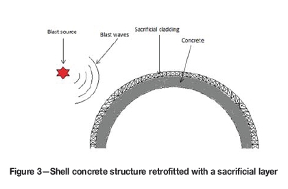
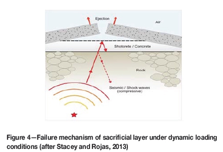
Figures 3 and 4 illustrate the sacrificial protection concept for a concrete shell structure exposed to external blast loading and a mine excavation (e.g. tunnel) subjected to a remote seismic event, respectively. In both scenarios presented, the ultimate purpose of the sacrificial layer is to protect the integrity of the structure by allowing the sacrificial protective layer to deform or fail under dynamic loading conditions.
Behaviour of sacrificial support in a rockbursting environment - a case study
After a study of shock waves in blasting and their application, Stacey (1991) proposed the wave trap mechanism approach to help tackle the problem of rock damage associated with rockbursts. He was motivated by the promising results obtained by Hino (1959), which demonstrated the potential to alleviate the impact of reflected shock waves and thus reduce rock damage.
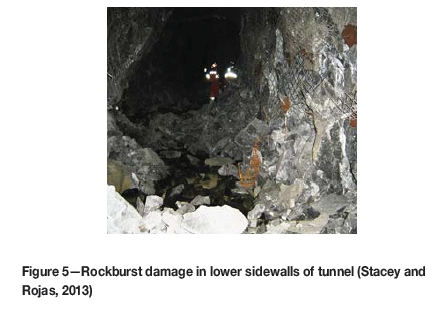
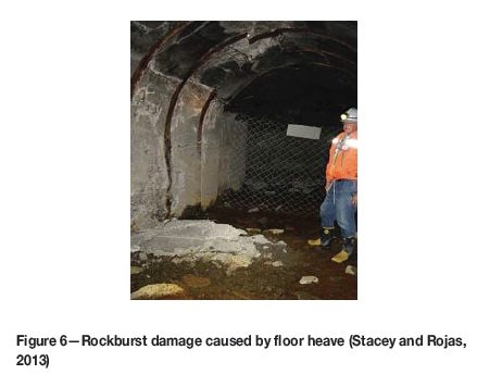
The experience gained in a rockburst event reported in a Chilean mine has presented possible evidence of the effectiveness of one of the previously suggested methods to help reduce wallrock damage induced by shock waves. Figures 5 and 6 show rock and support damage in tunnels as a result of the rockburst event. Figure 5 shows ejected rocks from both sidewalls of the tunnel, and the failure of support can easily be noted. In Figure 6, heave of the floor, which the authors (Stacey and Rojas, 2013) referred to as 'clean concrete', is apparent. The concrete was referred to as 'clean' because it was not covered with water or mud before the rockburst event. The interesting feature in both these figures is that where the floor is covered with water or mud there appears to be no damage to the rock. This raises the question as to whether the presence of the water or mud layer influenced the failure in some way.
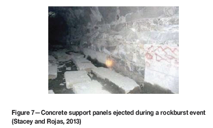
Stacey and Rojas (2013) further present a fascinating case pertaining to support behaviour in a dynamic loading environment. Figure 7 depicts some concrete panels, which initially were designed to provide stability to the tunnel walls, now lying on the floor of the tunnel. A close scrutiny of the figure shows that the wallrock was apparently undamaged after the rockburst event. This type of support was termed a sacrificial support because it saved the rock from damage, with failure experienced only by support itself. The sacrificial support concept can also be applied to the previously presented case. Both cases led the authors to develop a conceptual model to explain possible mechanisms of sacrificial support behaviour.
Tensile wave trap mechanism - a possible explanation of sacrificial support behaviour
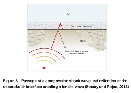
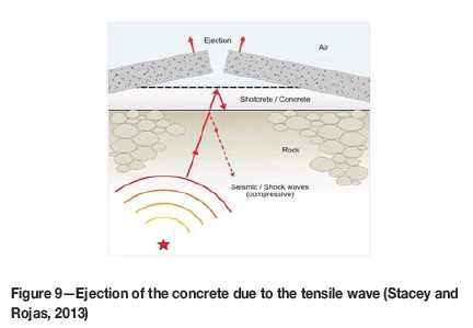
To understand the conundrum presented by the two incidents reported above, Stacey and Rojas (2013) developed a simple conceptual model, which is referred to as a tensile wave trap mechanism. The conceptual model assumes a seismic compressive wave generated from a point source which is distant from the excavation boundaries. In Figure 8, a seismic compressive wave is propagating through a rock medium lined with a concrete/shotcrete layer at the upper boundary, which in this case represents the tunnel excavation surface. Due to differences in the stiffness or mechanical properties between the rock and concrete, part of the propagating wave will be reflected (possible minor reflections) at the interface, and then propagation will take place through the concrete until reflection takes place at the concrete/air boundary. This is because air cannot support the passage of the compressive wave and thus the compressive wave will be reflected as a tensile wave. The reflected tensile wave will now travel back to rock/concrete interface and, owing to the fact that the interface has limited tensile strength, the tensile wave will remain trapped within concrete and ejection will take place as shown in Figure 9.
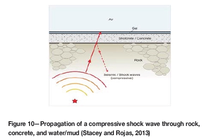
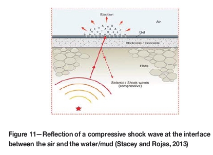
In order to interpret the mechanism for the cases where the tunnel floor was covered with water or mud (Figures 5 and 6), a rock medium supported with concrete was superimposed with a thin layer of gel representing water or mud (see Figure 10). A similar wave trap mechanism was also assumed in this regard. The seismic compressive wave will take a similar path from the point source and will be reflected as a tensile wave at the interface between the concrete and water/mud. As a result of the inability of water or mud to sustain tensile stresses, the wave is trapped and dissipated as a spray of water and mud (Figure 11), leaving concrete and rock undamaged. On the other hand, it can now be easily be inferred how floor heave had taken place in the area covered with fresh concrete.
The study by Stacey and Rojas (2013) left unanswered some important questions pertinent to sacrificial support behaviour. The research described in this paper aims to provide answers to the following questions pertaining to different support layers of the materials investigated:
► Is a minimum thickness required for the support layer to effectively resist dynamic rock failure (rockburst damage)?
► What are the effects of different stiffnesses of support layers/liners on their capability to combat the effects of stress waves?
A simple test method to demonstrate the mechanism of sacrificial support
It is difficult, if not impossible, to simulate real rockburst conditions, in either the field or the laboratory. Most of the studies conducted in the past on rock support performance under dynamic loading conditions have been through underground blasting experiments or drop weight tests (for example, Ortlepp and Stacey, 1997; Player et al., 2008). In blasting experiments, it has been noted that gas expansion plays a significant role in causing rock fragmentation, rather than rock failure being only a result of reflection of shock waves from a free surface, as would be expected in real rockburst situation. In drop weight tests, there is no interaction between the rock mass and support system, since testing is done by releasing a suspended mass with certain kinetic energy to impact directly on the support system. Both of these test methods should, however, be credited with providing some insights into support performance under dynamic loading conditions, but not on the basis of simulating real rockburst conditions (Stacey, 2012).
In light of the difficulties associated with simulating rockburst conditions, it was essential to search for a simple, yet robust, testing methodology that would enable dynamic rock fracturing to be studied in a controlled laboratory environment. The split Hopkinson pressure bar (SHPB) is one of the popular and well-established techniques used to test a range of materials at high strain rates.
Spall testing with the SHPB
In order to study spall failure phenomena, a single Hopkinson pressure bar may be used instead of the two-bar configuration often used for standard SHPB compression tests. Such a configuration has allowed the dynamic tensile strength of variety of materials such as ceramics (Najar, 1994; Johnstone and Ruiz, 1995; Galvez et al., 2000; Diaz-Rubro et al., 2002), concrete (Diamaruya et al., 1997; Klepaczko and Brara, 2001, 2006, 2007; Schuler et al., 2006), composites (Govender et al., 2009, 2011), and rocks (Rodriguez et al., 1994; Zhou et al., 2007) to be determined at high strain rates.
Govender et al. (2011) demonstrated the spall damage phenomenon for a long rod specimen directly impacted by a projectile. Specimen failure occurs at a location when the stress resulting from interaction between the incident compressive stress wave and reflected tensile stress wave exceeds the tensile strength of the material. This failure mechanism is common in situations in which the source of stress waves is distant from where failure occurs, e.g. failure observed in a tunnel remote from the seismic source. High ejection velocities in rockbursts often result in spall fragmentation, and this is a serious safety concern.
Shock/stress waves generated from a seismic event in a mining environment are complex to understand and simulate. As a result, a one-dimensional stress wave propagation approach was adopted for simplicity. Spalling phenomena described herein also assume a one-dimensional theory of stress wave propagation in elastic media, which can be represented by the following equation:
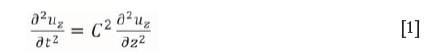
where, u is the displacement, t being time, and C the wave velocity.
Figure 12a shows a SHPB set-up for a spalling test of a long cylindrical specimen attached at the right-hand end of the Hopkinson pressure bar, while Figure 12b is a modification of the SHPB set-up with a liner attached to the specimen. Both the input bar and specimen are supported by bushings in order to minimize friction, and their movement is restricted to one degree of freedom in the x-direction. The bushings are aligned beforehand to ensure that the striker, input bar, and specimen are co-linear at the start of the test. Before testing of specimens, the input bar is calibrated for wave speed and stress level.
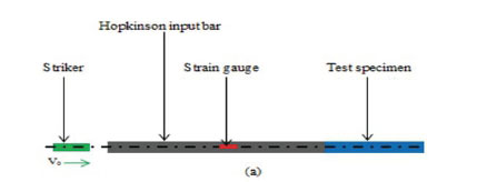
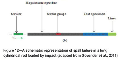
In order to induce a stress wave, a gas gun is used to propel the striker to impact the input bar. The generated transient strain pulse will then propagate down the input/transmitting bar as a longitudinal compressive stress wave, and on arrival at the bar/specimen interface, part of the compressive stress wave will be reflected back as a tensile stress wave due to bar/specimen impedance, whereas the remainder of the compressive stress wave will travel through the specimen and be reflected back at the free end. The transmission of stress waves at the contact between two-layered media is governed by their mechanical impedance (Z = pC0, where ρ is the density of material and C0 is the wave speed). To achieve satisfactory wave transmission at the bar/specimen interface in the SHPB, grease is often applied at the contact. A pair of strain gauges, cemented diametrically opposite at the mid-length of the input bar, is used to measure the amplitudes of incident and reflected waves. A calibration factor is then used to convert the recorded output voltage into stress. The dynamic stress pulse can be shifted in time from the centre of the bar to the bar/specimen interface using a time shift based on one-dimensional wave propagation.
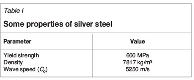
In this study, centreless ground silver steel was used for the input bar. The centreless ground bar ensures uniformity of the cross-sectional area and a straight neutral axis throughout the entire bar length (Gama et al., 2004). The input bar used had a nominal diameter of 25 mm and was 2000 mm long. KyowaTM strain gauges with length of 2 mm were glued at the mid-length of the bar. SHPB tests in general require a data acquisition system with a high sampling rate (Zhou et al., 2014). The stress wave signal, measured as output voltage at the input bar strain gauge station, was amplified before being recorded by a 16-bit data logger at 10 MHz. Table I summarizes some properties of the silver steel used in this study.
A profiled striker was machined from the same material as that of the input bar. A short striker was used as the projectile in order to induce a short pulse duration, which is ideal in the context of a spalling test, wherein a short pulse with wavelength less than the specimen length is a prerequisite in order to induce spall damage. Since the generated pulse could contain some oscillations, a pulse smoother was used to eliminate the Potchammer-Chree mode high-frequency oscillations. Regarding the impact of the input bar by the striker, care was taken to ensure that the bar was always loaded within its elastic limit.
Specimen preparation and materials characterization
Test specimens of anorthosite, norite, and marble rock types were prepared for both quasi-static and dynamic tests. Cylindrical rock specimens were obtained through laboratory core drilling, and all the specimens were cut to the required lengths. Thorough visual inspection was conducted to make sure all the test specimens were free of cracks or vein-like structures.
Quasi-static testing and results
It is important to determine the quasi-static rock mechanical properties before spall tests are conducted with the SHPB. One of the fundamental prerequisites of spall testing is that the test specimen must not be loaded beyond its compressive strength. With that in mind, the dynamic stress pulse magnitude in the SHPB can be controlled to below the compressive strength of the rock material by regulating the velocity at which the striker is fired. However, the reflected stress wave from the free end of the specimen must be sufficient to break the specimen in tension.
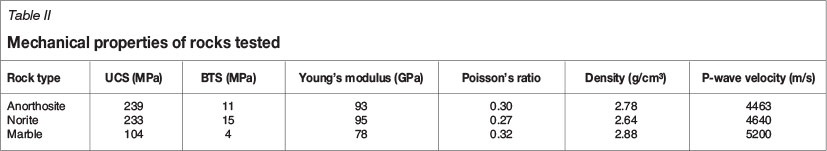
Accurate data on the mechanical properties of rocks is of paramount importance in the fields of rock mechanics and rock engineering. At least five specimens per rock type were subjected to two quasi-static tests. Table II summarizes the uniaxial compressive strength data and deformation properties (Young's modulus and Poisson's ratio) of anorthosite, norite, and marble. Data for Brazilian tensile strength (BTS) tests is also included in Table II. In addition, an ultrasonic technique was used to measure the wave speeds in the tested rock materials to aid in determining the impedance mismatch of rock relative to the Hopkinson pressure bar.
The UCS of anorthosite is slightly higher than that of norite, but both are higher than that of marble. With such high values of UCS for both rock types, one could intuitively assume that these rocks may be very brittle. Generally, brittleness has been determined on the basis of high ratio of uniaxial compressive strength to tensile strength. This notion has been refuted by several researchers due to a lack of plausible explanations as to how this ratio could be related to brittleness (Andreev, 1995; Denkhaus, 2003).
According to Tarasov and Potvin (2013), the brittleness of rock material dictates its ability to violently release the elastic strain energy stored within the rock. In the laboratory, this can be tested by conducting servo-controlled tests. Based on such testing, Tarasov and Randolph (2011) presented a criterion that can be used to determine rock brittleness without ambiguities. A stiff, servo-controlled rock testing machine was used to load a rock specimen under triaxial stress conditions in order to obtain the complete stress-strain curve. Two indices were then used to measure the intrinsic brittleness of rock using the following equations:
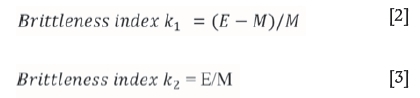
where E is the pre-peak elastic modulus and M the post-peak modulus (E and M are the gradients determined by the average method as in Figure 13).
A close look at the scale of brittleness index (k1and k1) shows a green dashed line near the extreme right end of the brittleness scale (Figure 13). This line clearly depicts the near absolute brittleness of anorthosite, as confirmed by the two calculated index values, k1 = 0.194 and k1 = 0.805. According to the scale, the index value k1 = 0 indicates absolute brittleness, whereas k1 = 1 (E = M) on the other hand also represents absolute brittleness. The positive slope of the post-peak curve shows that the rock exhibits Class II behaviour, and rocks in this class are generally brittle (Tarasov and Potvin, 2013). This is evident in the complete stress-strain curve inserted above the brittleness index scale. The norite rock tested in this study also falls in the Class II category, but was found to be less brittle than anorthosite. Evaluation of brittleness of rock material has often been neglected in SHPB testing of rock at high strain rates as the focus of these investigations has been on determining the stress-strain relationship.
Spall test specimen preparation
Spall testing requires relatively long cylindrical specimens. The diameter of the specimens is the same as that of the Hopkinson pressure bar to be used, to facilitate even loading across the specimen face. In this study, an input bar with nominal diameter of about 25 mm was used, hence all the spall test specimens were prepared with a similar diameter. The range of lengths of rock specimens tested was between 285 mm and 350 mm. All test specimens used were free from cracks or vein structures and fairly homogenous.
Combating dynamic rock failure using a sacrificial layer: experimental observations from SHPB tests
Different liner materials were tested to evaluate their potential to prevent rock spallation using the experimental set-up described above. A liner refers to the material attached at the free end of rock specimen, and it must have a similar diameter to the rock specimen to avoid specimen/liner area mismatch. Before the performance of various liners could be evaluated, rock specimens were tested without any form of liner to allow the rock the freedom to fail dynamically due to the effect of the reflected tensile stress wave from the free end. The effect of the liner material's mechanical stiffness and its thickness (length) in preventing spall damage ('rockburst' damage) are investigated in this section.
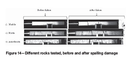
Brief summary of experimental results for tests without liners
Figure 14 shows example images of failed rock specimens without liners captured by the high-speed camera. All specimens were tested at relatively similar loading conditions by controlling the striker impact velocity. All the failed specimens are characterized by multiple fragmentation patterns.
Experimental results for tests with liners
Concrete and clay liners were chosen following observations of the behaviour of sacrificial layers in a real rockburst event as previously reported. The concrete had a density of 2500 kg/m3 and a p-wave velocity of 3440 m/s.
The liners used are considered to be a fair representation of low to high impedance mismatch between rock specimen and support liner. The performance of various liner materials under dynamic loading is described below.
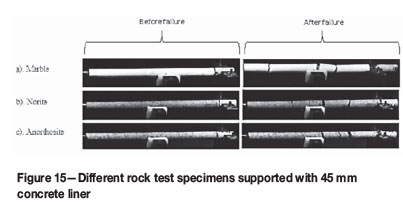
Tests with 45 mm thick concrete liner (concrete liner series)
A weak fine-grained concrete was used in this study, and it was allowed to cure for 14 days. Initially, all the concrete liners were arbitrarily prepared at a nominal thickness of 45 mm as part of a trial run. Figure 15 shows the behaviour of different rock types supported by concrete liners with this nominal thickness There is relatively little difference in terms of rock fragmentation patterns, despite the introduction of the liners, as compared with the behaviour of rock specimens reported above without liners.
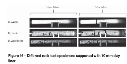
Tests with 10 mm thick clay liner (clay liner series)
The clay material of choice used in the study was bentonite. Bentonite and water were thoroughly mixed in a container to produce a slurry-like mix. The minimum thickness for the clay liner was 10 mm and a plastic tube was used to contain it. It was difficult, if not impossible, to fill the plastic tube containment beyond a thickness of 50 mm for the parametric study, due to difficulties associated with handling wet clay.
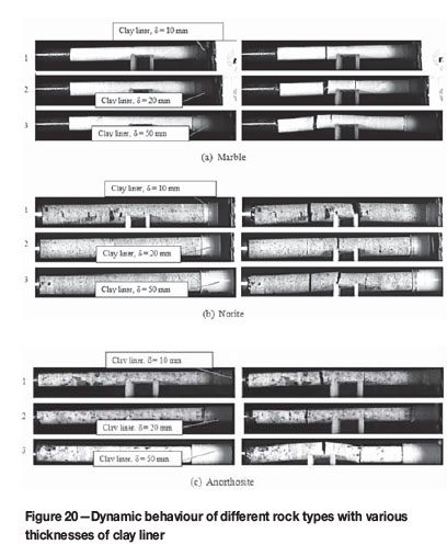
From the photographs in Figure 16, marble specimens spalled at one location, resulting in two fragments. This is an interesting result illustrating the ability of clay to alter the strength of the dynamic stress wave. Anorthosite and norite, in contrast, are characterized by a two-spall fragmentation pattern.
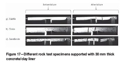
Tests with 30 mm thick concrete/clay liner combination (concrete/clay series)
A combination of concrete and clay was investigated in order to assess its effectiveness in preventing dynamic rock failure. This composite concrete/clay liner was made up of 20 mm of concrete and 10 mm of thin clay. All the rock test specimens in Figure 17 show a three-spall fragmentation pattern.
Discussion
This section provides some useful insights into the effect of varying liner thickness on dynamic rock failure. In addition, the effect of impedance mismatch in layered systems and its influence on rock damage is also assessed.
Effect of liner thickness on dynamic rock failure
Concrete liner series
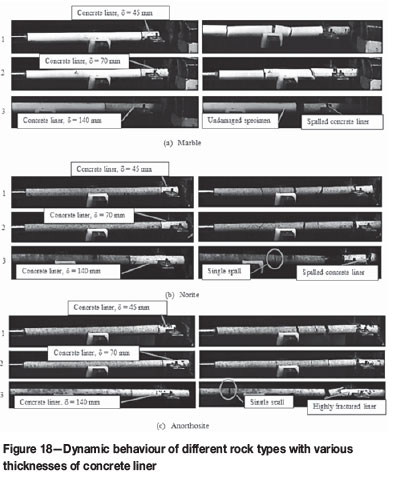
Figure 18 depicts the behaviour of different rock types with concrete liners of 45 mm, 70 mm, and 140 mm. Frames 1, 2, and 3 indicate the decrease in rock fragmentation as the concrete liner thickness increases. Increasing the liner thickness reduced spall damage for all three rock types tested. Marble test specimens with the maximum thickness (approx. 140 mm) of concrete liner showed no dynamic rock damage, and this is how a sacrificial support ought to behave under dynamic loading.
Concrete/clay liner combination
The thickness of concrete liner was varied while that of the clay liner was kept constant at 10 mm throughout testing. The results can be seen in Figure 19.
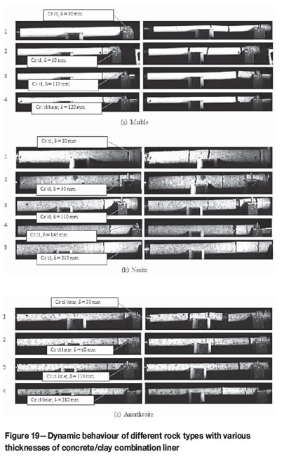
For marble test specimens, failure was inhibited with liners 110 mm and 120 mm thick. This indicates that the clay liner could have absorbed the stress wave at the concrete/clay liner interface, resulting in a decrease in strength of the reflected tensile wave at the contact, reducing its ability to re-enter the rock specimen and cause damage by stress wave superposition. Spall damage was prevented in both anorthosite and norite when the liner thickness was 200 mm. There are two possible reasons for such behaviour. Firstly, the duration of the transmitted stress wave in concrete could have been prolonged, decreasing the chances of cyclic loading of the rock specimen resulting from the reflected tensile stress wave which in turn may cause spall damage. In addition, spalling of liner support as observed in case of longer liners might have helped to reduce the strength of the reflected tensile wave from the concrete/clay liner contact through energy loss during the fracturing process. Secondly, damage was not apparent in either rock type due to the presence of the clay liner, as explained earlier.
Clay liner series
This series shows the opposite behaviour in terms of its ability to help combat dynamic rock fracturing. The behaviour of marble specimens with clay liner is anomalous, since the number of fragments increased as the liner thickness increased, while the opposite held for the other liner types. In brief, all the test specimens failed despite an increase in liner thickness. This raises a fundamental question regarding the effectiveness of using 'soft' liner materials as support, and this is further considered in the following section.
Effect of mechanical impedance on rock damage in layered systems
It was not practical to cement strain gauges on both the rocks and the support liners in order to mirror the propagation of stress wave in the whole SHPB set-up. Instead, a basic analytical approach was used to determine the coefficients of transmission and reflection by means of the following equations:
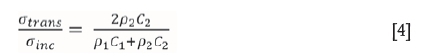
and
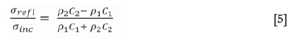
The subscripts 1 and 2 denote the Hopkinson pressure bar and rock specimen respectively. In cases when there are more than two liners, as in this study, Equation [4] can be applied consecutively to determine the transmission ratio into the third layer.
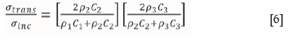
Subscripts 3 in this regard represent a support liner. The transmitted stress wave in the second layer can be used as an incident stress to the third layer from Equation [6].
Tedesco and Landis (1989) reasoned that if the transmission and reflection of a stress wave in layered media is a function of impedance mismatch, then mechanical impedance could be manipulated to prevent internal damage of a layered structure subjected to external blast loads. Such an approach could also assist in preventing rock damage to an excavation supported with a liner under dynamic loading. Generally, all the 'layers' constituting the HPB in this study had different mechanical impedances, which can mathematically be expressed as: p1C1> p2C2> p3C3. The Hopkinson pressure bar was dynamically loaded in the stress region between 80 MPa and 100 MPa. The percentage of transmitted stress wave in the first two liners was sufficient to cause spall damage to rock upon reflection from the specimen's free end. At least 46% of the stress wave was transmitted to the rock test specimen for all rock types, while 54% was reflected back to the steel bar. About 80 MPa was assumed as the input stress wave in the steel bar.
One of the liners that showed better performance in reducing or inhibiting rock damage is concrete. When the transmitted stress wave in the second layer is taken as an incident stress wave to the third layer (Equation [6]), it was found that at least 80% of the stress wave was transmitted into the concrete for all rock types. To put this into perspective, the concrete used had high transmission ratios, and the reflected tensile wave was not strong enough to initiate rock damage, particularly in the case of marble test specimens with the maximum thickness of concrete liner. It has been observed that a 'perfect' impedance mismatch is not in itself sufficient to prevent dynamic rock failure. When a minimal thickness of concrete liner is used, it only traps the momentum transferred from the excited rock without necessarily altering the strength of the stress wave at the contact. On the other hand, relatively long specimens permit the passage of the stress wave through the liner, and the liner is damaged upon reflection of stress wave from the free end. It is postulated that, if the thickness of concrete liner was further increased to 200 mm for the anorthosite and norite test specimens, failure could have been totally eliminated.
In the case of the composite concrete/clay liner, test specimens of all rock types were protected from damage when a certain threshold of liner thickness was reached. The behaviour of the rock was primarily influenced by the mechanical impedance of concrete as described above, and by the clay liner as a secondary effect.
If less dense material is used as a liner to provide rock support, the greater will be the coefficient of reflection of the stress wave, resulting in significant rock damage. The behaviour of rock subjected to dynamic loading reported for the clay liner series is attributed to the low acoustic impedance of the clay.
It can be concluded that having a liner material in place with the appropriate impedance relative to the rock is not sufficient to prevent rockburst damage, and the effect of varying liner thicknesses should also be considered. However, it is not possible at present to provide definite answers regarding the relationship between a liner's thickness and mechanical impedance. The use of low-impedance liner material relative to rock is not ideal in attempting to help combat rock damage.
Conclusions
More than two decades ago, Stacey (1991) proposed a wave trap concept for rock support, aimed at preventing rockburst damage. The mechanism of behaviour of the suggested support concept was proven years later in real rockburst events in a mine (Stacey and Rojas, 2013). Such cases helped to validate the mechanism of sacrificial support in rockburst events.
This paper has demonstrated, through controlled laboratory experiments, the potential benefits of using a sacrificial layer to help combat the effects of rockbursts caused by seismically induced shock/seismic waves. The comparison of case studies reported earlier in the paper and observations from laboratory experiments showed significant agreement in terms of the behaviour and performance of sacrificial support. For instance, the relatively weak concrete and concrete/clay combinations as liners performed significantly better in preventing dynamic rock failure, as indicated in the diagrams for both cases of sacrificial support behaviour reported by Stacey and Rojas (2013).
The sacrificial support concepts reported here can find a wide range of applications in different areas such as tunnels (including the floor), shafts subjected to seismic loading, and buried structures subjected to external blast loads. This study is the first of its type to practically demonstrate the potential use of sacrificial support in helping to limit rockburst damage and to enhance safety in mines. The performance of sacrificial support can, however, be enhanced by other support elements such as cable anchors, yielding rockbolts, wire mesh, and straps to help retain and contain the detached sacrificial layer (Rizwan and Stacey, 2015; Stacey and Rojas, 2013).
Future work will be aimed at development of design guidelines for sacrificial support. A quantitative relationship between liner thickness, mechanical impedance of both rock and liner, and loading parameters must be established analytically. Verification of this relationship would entail a broader experimental programme involving different liner materials, supported by numerical simulations. Once design guidelines are established, field observations can then follow in real, seismically active mining environments.
Acknowledgement
Some of the research on which this paper is based was supported in part by the National Research Foundation of South Africa (Grant-specific unique reference number (UID) 85971). The Grantholder (third author) acknowledges that opinions, findings, and conclusions or recommendations expressed in any publication generated by NRF-supported research are those of the author, and that the NRF accepts no liability whatsoever in this regard.
References
Andreev, A. 1995. Brittle Failure of Rock Materials. Balkema, Rotterdam. 123 pp. [ Links ]
Brara, A. and Klepaczko, J.R. 2006. Experimental characterization of concrete in tension. Mechanics of Materials, vol. 25. pp. 253-267. [ Links ]
Brara, A. and Klepaczko, J.R. 2007. Fracture energy of concrete at high loading rates in tension. International Journal of Impact Engineering, vol. 34. pp. 424-435. [ Links ]
Denkhaus, H.G. 2003. Comment on 'The evaluation of rock brittleness concept on rotary blast hole drills and correlation of specific energy with rock brittleness concepts on rock cutting.' Journal of the Southern African Institute of Mining and Metallurgy, vol. 103. pp. 523-525. [ Links ]
Diamaruya, M., Kobayashi, H., and Nonaka, T. 1997. Impact tensile strength and fracture of concrete. Journal de Physique. IV Colloque, vol. 7 (C3). pp. 253-258. [ Links ]
Diaz-Rubio, F.G., Perez, J.R., and Galvez, V.S. 2002. Spalling of long bars as reliable method of measuring the dynamic tensile strength of ceramics. International Journal of Impact Engineering, vol. 27, no. 2. pp. 161-177. [ Links ]
Gamma, B.A., Lopatnikov, S.L., and Gillepsie, J.W. 2004. Hopkinson bar experimental technique: a critical review. Applied Mechanics Reviews, vol. 57. pp. 223-250. [ Links ]
Govender, R.A., Louca, L.A., Pullen, A., and Nurick, G.N. 2009. High strain rate delamination of glass fiber reinforced polymers using a Hopkinson configured for spalling. Proceedings of DYMAT 2009 - International Conference on the Mechanical and Physical Behaviour of Materials, Brussels, Belgium. 7-11 September 2009, vol. 1, pp. 449-455. [ Links ]
Govender, R.A., Louca, L.A., Pullen, A., Fallah, A.S., and Nurick, G.N. 2011. Determining the thorough-thickness properties of thick glass fiber reinforced polymers at high strain rates. Journal of Composite Materials, vol. 46. pp. 1219-1228. [ Links ]
Hino, K. 1959. Theory and Practice of Blasting. Nippon Kayaku, Tokyo. 169 pp. [ Links ]
Johnstone, C. and Ruiz, C. 1995. Dynamic tensile strength of ceramics. International Journal of Solids and Structures, vol. 32. pp. 2647-2651. [ Links ]
Najar, J. 1994. Dynamic tensile fracture phenomena at wave propagation in ceramic bars. Journal de Physique, vol. 4. pp. 647-652. [ Links ]
Ortlepp, W.D. 1997. Rock Fracture and Rockbursts - an Illustrative Study. Southern African Institute of Mining and Metallurgy, Johannesburg, 255 pp. [ Links ]
Ortlepp, W.D. and Stacey, T.R. 1997. Testing of tunnel support: dynamic load testing of rock support containment systems. Safety in Mines Research Advisory Committee, SIMRAC GAP Project 221. Johannesburg. [ Links ]
Player, J.R., Thompson, A.G., and Villaescusa, E. 2008. Dynamic testing of reinforcement systems. Proceedings of the 6th International Symposium on Ground Support in Mining and Civil Engineering Construction, Cape Town. Stacey, T.R. and Malan. D. (eds.). Symposium Series S51. Southern African Institute of Mining and Metallurgy, Johannesburg. pp. 581-595. [ Links ]
Potvin, Y. and Wesseloo, J. 2013. Towards an understanding of dynamic demand on ground support. Journal of the Southern African Institute of Mining and Metallurgy, vol. 113, no. 12. pp. 913-922. [ Links ]
Rizwan, M. and Stacey, T.R. 2015. Conceptual systems to limit damage to tunnel floors in rockbursting environments. Proceedings of the 13th International Congress of the International Society of Rock Mechanics, Montreal, Canada, 10-13 May 2015. International Society for Rock Mechanics. paper no. 264. [ Links ]
Schuler, H., Mayrhofer, C., and Thoma, K. 2006. Spall experiments for the measurement of tensile strength and fracture energy of concrete at high strain rates. International Journal of Impact Engineering, vol. 32. pp. 1635-1650. [ Links ]
Stacey, T.R. and Rojas, E. 2013. A potential method of containing rockburst damage and enhancing safety using a sacrificial layer. Journal of the Southern African Institute of Mining and Metallurgy, vol. 113. pp. 565-573. [ Links ]
Stacey, T.R. 2013. Dynamic rock failure and its containment - a Gordian knot design problem. Proceedings of the First International Conference on Rock Dynamics and Applications (RocDyn 1) - State of the Art, Lausanne, Switzerland, 6-8 June 2013. CRC press/Balkema. pp. 57-70. [ Links ]
Stacey, T.R. 2012. A philosophical view on the testing of rock support for rockburst conditions. Journal of the Southern African Institute of Mining and Metallurgy, vol. 113, no. 7. pp. 227-245. [ Links ]
Stacey, T.R. 2011. Support of excavations subjected to dynamic (rockburst) loading. Proceedings of the 12th International Congress of the International Society of Rock Mechanics, Beijing, China. CRC press/Balkema. pp. 137-145. [ Links ]
Stacey, T.R. 1991. Method of and means for inhibiting rockbursts. Patent Application, Provisional Specification, registered through Adams and Adams, Patent Attorneys, Pretoria. [ Links ]
Tarasov, B.G. and Potvin, Y. 2013. Universal criteria for rock brittleness estimation under triaxial compression. International Journal of Rock Mechanics and Mining Sciences, vol. 59. pp. 57-69. [ Links ]
Tarasov, B.G. and Randolph, M.F. 2011. Superbrittleness of rocks and earthquake activity. International Journal of Rock Mechanics and Mining Sciences, vol. 48. pp. 888-898. [ Links ]
Tedesco, J.W. and Landis, D.W. 1989. Wave propagation through layered systems. Computers and Structures, vol. 48. pp. 625-638. [ Links ]
Zhou, Y.X., Xia, K., Li, X.B., Li, H.B., Ma, G.W., Zhao, J., Zhou, F., and Dai, F. 2012. Suggested methods for determining the dynamic strength parameters and mode-I fracture toughness of rock materials. International Journal of Rock Mechanics and Mining Sciences, vol. 49. pp. 105-112. [ Links ]
Paper Received Apr. 2016
Revised Paper Received Jun. 2016

