


Services on Demand
Article
 English (pdf)
 Article in xml format
 Article references
Indicators

Related links
-
 Cited by Google
 -
 Similars in Google
Share

 Permalink
Journal of the Southern African Institute of Mining and Metallurgy
On-line version ISSN 2411-9717
Print version ISSN 2225-6253
J. S. Afr. Inst. Min. Metall. vol.116 n.11 Johannesburg Nov. 2016
http://dx.doi.org/10.17159/2411-9717/2016/v116n11a3
WITS SPECIAL EDITION - VOLUME I
A review of rock cutting for underground mining: past, present, and future
D. Vogt
Centre for Mechanised Mining Systems, University of the Witwatersrand Johannesburg, South Africa
SYNOPSIS
Rock has been cut in the process of mining since before the invention of explosives. Today, we seek to return to cutting to reap the benefits of continuous operations for South African underground hard-rock mines, to improve speed of access to the orebody, and to improve the efficiency of mining operations.
Development of new technology fits within a framework of engineering knowledge. By understanding the characteristics of the rock, the tools we use to cut it with, and the history of mining and rock cutting, we can see the genesis of the roadheader, the longwall, and the continuous miner, all drag bit cutters. They have emerged as the solutions of choice for underground mining of softer materials such as coal and potash.
In hard rock, the challenges are the forces required to break the rock, and the wear of the tools caused by the rock's abrasiveness. Only disc cutters currently handle the challenges, and even then, often not economically. New materials like thermally stable diamond composite will help, as will combinations of mechanical cutters and other methods such as high-pressure water or high temperatures.
It is not clear what will emerge as the consensus technique for hard-rock cutting. Experience teaches that development is expensive and the market is small. Will mining companies partner with equipment developers to make the technological leap? Or will the solution come from a systems approach, not considered here?
Keywords: rock cutting, continuous operations, mechanization.
Introduction
Blasting is the dominant method of breaking rock for the purposes of mining. When used underground, blasting is part of a batch process. If rock can be cut rather than blasted, mining can become continuous, leading to process and efficiency improvements.
Coal produced from underground mines is now predominantly excavated using mechanical means, but underground hard rock is still broken primarily by explosives.
This paper traces the history of rock cutting, reviews the main physical processes that are or could be used, and comments on the future. It is written from the perspective of narrow-stope hard-rock mining typical of South African gold and platinum mines.
This review is not definitive, but covers the most important experiences in rock cutting that are applicable to the South African hardrock environment, and discusses the future of practical techniques, as well as briefly examining some more speculative methods. The issue of the mining system is not a primary consideration - it is a topic for another paper.
The need for rock cutting
Rock cutting offers a number of advantages over drill-and-blast mining. Possibly the most significant is that cutting offers the opportunity for continuous operations. Blasting introduces a cycle into mining, which then forces a batch mode on the process: drill, blast, clean, support. Particularly on larger mines, where all blasting occurs at about the same time, the mining process must fit into the defined time between blasts. If the drilling, cleaning, and supporting take less than the allocated time, then time is wasted. If they take longer, then the next blast is missed. In both cases, the rigid timing leads to system inefficiency. The move to continuous processes is now considered the key to improved productivity in industry, as part of the Lean philosophy (Womack and Jones, 2003), and offers the same benefits for mining.
Mechanical methods of tunnelling have the potential to be significantly faster than drill-and-blast methods. In the context of mining, earlier access to the orebody considerably increases the net present value of the mine.
Rock cutting has a number of other advantages:
► In tunnelling and other applications that might be close to human settlements, cutting generates significantly lower vibration and noise levels than the use of explosives
► The cutting process affects the rock surrounding the excavation less than explosives, thus the rock stronger is and safer (or easier to support)
► Particularly in tunnelling, cutting can produce excavations very close to the desired shape and size, so that the cost of extra lining due to overbreak is reduced
► The number of people exposed to dangerous underground conditions is reduced; as is the need to store and handle explosives
► If cutting can be applied with discrimination, particularly on narrow reefs, it offers the opportunity to greatly reduce waste dilution in a process that has similar advantages to ore sorting (Cook, 1969)
► If the mine can be created with smaller excavations because it is cut, the seismicity and ventilation requirements will both be reduced, reducing both risk and cost.
Engineering knowledge
In the normal development process, new engineering knowledge is generated mainly by variation and selection (Vincenti, 1994). Against the background of a problem, engineers develop a variety of solutions and through a process of selection choose the best. In the case of rock cutting, the selection has been made for coal and soft rock, but the 'best' selection is by no means clear for hard-rock cutting.
Outside of the normal development process, there is also the revolutionary process, driven by a 'presumptive anomaly'. In this case, someone identifies a need that will arise in the future, and proposes a revolutionary change to meet that need. The jet engine is a classic example: it was proposed at a time when aircraft could not yet handle more speed or power, and at a time when it was not yet clear how to create better engines. A number of far-sighted individuals presumed that in the future there would be a need for jet engines, and started the process of development (Constant, 1973).
At present, there are a number of methods proposed to cut rock that rely on new technology. The need has been seen, and individuals have visions as to how that need may be met. None of the proposed methods have as yet progressed far past laboratory testing or become accepted by consensus as a practical solution.
Rock properties
The relationship between rock properties and cutting is complicated. The major properties are briefly described here. The uniaxial compressive strength, or UCS, is the most widely quoted parameter, but cutting performance depends on many other parameters in quite complex ways. Some of the best known measures of rock-cutting performance are the range of indices developed by the Norwegian University of Science and Technology (NTNU), for example those in Zare and Bruland (2013). The parameters discussed here are those most often quoted in the literature.
Strength
Rock varies widely in strength. The International Society of Rock Mechanics classifies rock strength based on the UCS of a sample (Table I). Strong rock requires higher forces to be applied before it will break.
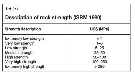
Most rocks are stronger in compression than in tension by a factor of about ten (Figure 1). Rock-breaking techniques like blasting that can break rock in tension will have lower specific energy of excavation.
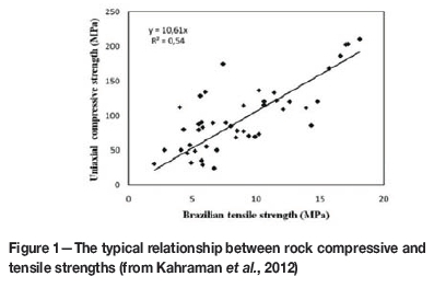
Brittleness
A material is brittle if, when subjected to strain, it breaks without first undergoing significant deformation. Brittle rock is easier to break than more ductile rock. There is no universal measure of brittleness, but a useful indicator is the ratio of compressive strength measured as UCS to tensile strength measured using the Brazilian test (Gong and Zhao, 2007). Going by that measure, data points in Figure 1 that lie below the line indicate lower brittleness, and those above the line higher brittleness.
Brittleness is also an important property of cutting tools.
Abrasiveness
While the strength and brittleness of a rock dictate how much force is required to break it, its abrasiveness determines how quickly the cutting tool will wear. Abrasiveness is not as easy to measure as rock strength, because it is not an intrinsic physical parameter but depends on the tool, method of excavation, applied loads, and other factors (Plinninger and Restner, 2008).
One practical estimate of abrasiveness is the observed tool lifetime (Table II). In situ measurement has the advantage of taking into account large-scale geotechnical factors such as rock mass rating, or RMR. It cannot be used on samples, and so is not helpful before mining starts.
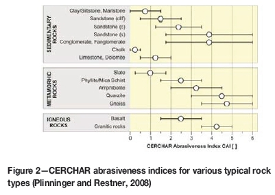
The most common measurement of abrasiveness is the Cerchar Abrasiveness Index (CAI). It is derived from a simple laboratory test machine, and is reasonably well correlated with other abrasiveness indicators (Plinninger and Restner, 2008). It has also been empirically correlated with tool wear rates for a number of tools in combination with the UCS. CAI varies from not abrasive (below 0.5) to extremely abrasive (above 4.5). Some values for typical rock types are plotted in Figure 2.
Specific energy ofexcavation
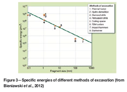
The specific energy of excavation (SEE) is not a rock property, but a property of a rock-cutting process. The SEE is the energy required to break a specific quantity of rock and is an important characteristic, because it dictates how much power will be required in a mining machine to mine at a given rate. SEE is theoretically determined by the energy needed to create free faces, because breaking a volume of rock into large chunks takes less energy than breaking it into fine material. In practice, there are orders of magnitude of difference between the theoretical energy required to create free faces and the actual energy used in practical rock-breaking techniques, but there is still a good correlation between lower specific energy and larger particle size.
Figure 3 shows results established for eight different breaking methods in one rock type: quartzite. The curve fitted to the data shows the effect of fragment size - smaller fragments require more energy. Explosives, wedge impact hammers, and diamond drills are more efficient than the average shown by the curve; thermal fusion and hydro-demolition are worse, while other methods lie close to the average.
The actual specific energy is also related to the rock condition: fractured rock requires less specific energy to excavate than solid, intact rock. The RMR is used to quantify the quality of the rock. It can be defined in various ways, and is used as a controlling factor in the design of support systems (Bieniawski, 1989). In a reversal of usual practice, Bieniawski et al. (2012) have used measurements of SEE to determine the RMR ahead of a tunnel using tunnel boring machines.
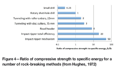
Hughes, described a consistent ratio of compressive strength (fc) to specific energy (ES) related to the mechanism of breaking, as illustrated in Figure 4. He found that the ratio is largely accounted for by the increasing size of the chips produced by each method, supporting the findings illustrated in Figure 3 (Hughes, 1972).
History
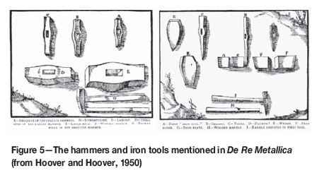
Since the development of iron tools, rock cutting has been used in mining. Agricola describes the status quo in the mid-loth century when rock was broken either by hammer and chisel (Figure 5) or by fire:
'Miners dig out crumbling ore with the pick alone. [...] They break a hard vein loose from thefootwall by blows with a hammer upon the first kind of iron tool, [...] When the rock of thefootwall resists iron tools, the rock of the hangingwall certainly cannot be broken unless it is allowable to shatter it by fire. (Hoover and Hoover, 1950)'
Agricola comments that fire shatters the hardest rocks, but the method of its application is not simple and goes on to explain the methods in detail for different situations.
It was not until the introduction of gunpowder that miners had access to a simpler method of breaking hard rock. Almost as soon as it was introduced nearly simultaneously in several mines across Europe in the first half of the 17th century, gunpowder was placed in holes drilled in rock (Barnatt et al., 1997; Vergani, 2002 translated in Vergani, 2009). The holes themselves were drilled using tools illustrated in Figure 6, principally borers that were hammered. Initially, soft rock was still mined by hand using picks, and very hard rock was still broken using heat.

Dynamite was patented in 1867 (Nobel, 1868) and the pneumatic drill was developed in the last half of the 19th century (Drinker, 1882). The combination of the two made drilling and blasting the technique of choice for underground hard-rock mining.
In coal, the situation was a little different. Coal in some coalfields is soft enough to break by hand using a pick, and in thin seams such as those near Durham in England, the low mining height meant that cutting by hand continued until the introduction of pneumatic picks (Trist et al., 1963). Explosives were used to break hard coal and rock when required, but were generally not favoured as they were expensive and could only be set off by qualified people.
Cutting using handheld picks was still used in coal mines in the UK until well into the 20th century. It remains true that where it is possible, a person using a pick is the most energy-efficient way of breaking rock due to the human ability to identify weaknesses in the rock and exploit them with flexibility (Roxborough et al., 1981).
The general situation in coal mining led to early mechanization using a combination of various machines, initially belt conveyors followed by the predecessors of today's longwalls and continuous miners.
The other major driver for rock cutting has been in tunnelling, where cutting has distinct advantages due to its low levels of vibration, reduced ventilation requirements, and potential for continuous operations. The first full-face tunnel boring machine (TBM) was developed by Charles Wilson in the USA and patented in 1856 (Madi et al., 2008). The face was excavated using disc cutters. Initial trials on the Hoosac tunnel were abandoned after 3 m due to problems with the disc cutters.
As with pneumatic drills, this was a period of rapid development around the world, with many inventions being patented. Frederick Beaumont built two machines to a patent from Colonel T. English that used replaceable chisels on an arm that was forced into the face using a hydraulic cylinder. The two machines were used to drive the Channel Tunnel from 1881 to 1883 and worked very successfully until the project was abandoned for political reasons. One machine advanced 1840 m on the French side, while the other advanced 1850 m on the English side, with a maximum daily advance rate of 25 m, exceptional for the time (Madi et al., 2008).
The next major development leading to modern tunnel boring machines was the machine designed by Robbins in 1953 for water tunnel boring near Pierre, South Dakota in the USA. It was successful, and proved that TBMs could be economically viable. In retrospect, the rock at Pierre was almost perfect for the method, which helped the cause of TBMs. Robbins' major success was in 1956, on a Toronto sewer project, when he showed that discs could cut on their own, without the need for picks (Hapgood, 2004). With time, TBMs developed to be able to tunnel even the hardest rock (Hansen, 1998). TBMs that were developed to handle soft ground are not considered here.
Another trend in rock cutting is the use of impact. The miners described by Agricola were breaking rock using impact forces. In fact, most rock broken by hand today is broken using an impact action from a hammer or pick, or a powered hammer - the pneumatic rotary-percussive drill. However, impact tools have had only limited use in production underground.
Rock cutting in South Africa
As early as the 1960s, South African gold mines were interested in implementing some form of continuous mining system, for many of the reasons already raised:
► Continuous mining can deliver higher rates of face advance
► The same tonnage can be delivered from fewer faces
► Cutting generates less fine material, which is associated with gold losses
► Cutting can enable sorting of waste and reef at the face
► Potential to mine narrower cuts with less dilution.
Two schools of thought emerged. The Chamber of Mines Research Organization ultimately pursued an approach based on directly breaking the bulk rock, particularly using impact tools. Anglo American pursued a different route; slot-based mining. Slots were cut above and/or below the block of rock to be mined, to provide two free faces, then the rock between the slots was broken using a variety of mechanical methods (Dunn, 1989).
Gold - Chamber of Mines research
In the early 1960s, the Chamber of Mines established a mining research laboratory, later known as COMRO (Leon et al., 1995), and soon began to devote research effort to alternative means of mining gold on the Witwatersrand. Neville Cook, director of the research laboratory from 1964 (UCB, 1998) was an early advocate for the subject, arguing for rock cutting and related in-stope sorting of waste (Cook, 1970).
Cook (1970) asserted that it is partly the clamping forces of the high rock stress at depth that makes rock-breaking difficult. A machine was therefore trialled that cut two slots using drag bits, '10 feet long, 10 inches apart to a depth of about a foot, in increments from 0.1 to 0.5 inch.' The slots marked the top and bottom boundaries of the economic horizon in the reef, and the rock between the slots was broken by the deflection of the vertical stress, in a similar manner to the discing experienced when diamond drilling at depth.
The machine cut 150 m2 in six months, at about three times the cost of conventional mining. This was viewed as an important first step in hard rock cutting, particularly as it enabled separate mining of a narrow reef band and waste, allowing for waste to be sorted and moved into the back area instead of incurring the costs of being transported to surface. A detailed technical description and brief history of the various versions of the machine is in Hojem et al. (1971). Similar drag-bit type cutting trials were also later undertaken in the USA (Morrell et al., 1986).
By 1975, the understanding of the problem and its solutions were considered to be good enough for a major programme of machine development to be undertaken. Three cutting methods were trialled: rock breaking, rock cutting, and reef boring (Fenn and Marlowe, 1990).
The economic basis for mechanization is discussed by Joughin (1976), who also presented a detailed set of requirements for a mining machine, including performance, machine configuration, power supply, manoeuverability, maintenance, and rock-breaking, rock-handling, and support considerations.
Boring out the reef using raiseboring technology was trialled (Joughin, 1976) using pilot holes reamed out to 500 mm diameter. A geological analysis (Jager et al., 1975) found that there was little benefit to using small-diameter boreholes to reduce dilution because the reef was not straight on the scale of 20 m to 30 m. If the hole diameter was increased, the method became uneconomical in many circumstances. In the early 1980s De Beers developed a hollow stope cutting tool, the Stope Corer, but it was uneconomic (Mulgrew, 2015).
By 1978, a better understanding of rock fracturing due to mining at depth was starting to inform new rock-breaking techniques (Joughin, 1978). Interest in slot cutting at COMRO declined due to its theoretical production limits, linked to its specific energy. Slot-cutting efficiency could be enhanced by the simultaneous application of high-pressure water (Hood, 1976).
Slot cutting requires very high cutting forces. Experimental work started on machines designed to lower the force experienced by the machine by using impact mechanisms. The first was the swing-hammer (Joughin, 1978). It was very successful at breaking rock, but suffered from poor angle of attack, which in turn led to problems when breaking hard patches, and also poor tool life. It was a complex mechanism, with a limit to its blow-energy potential.
The impact ripper was capable of much higher blow energy, and higher blow rates. The hammer could be directed to easily work with mining-induced fracturing, lowering the specific energy. The initial trials at the Elsburg Gold Mining Company were successful (Nicoll, 1976) and development work continued. However, even the first trial revealed that the performance was highly dependent on the condition of fracturing of the face, 'on solid unfractured rock, there was virtually no impression' (Nicoll, 1976). This turned out to be an insurmountable problem in the long run.
By 1987, the impact ripper hammer had been reduced in size to half the length and mass of commercially available hydraulic hammers of similar blow energy, and had been developed to run on clear water rather than hydraulic fluid. Rock could be removed at an average rate of 9.5 m3 per impacting hour, by a hammer running at 5 Hz with a blow energy of 2.5 kJ (Haase and Pickering, 1987).
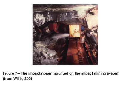
The final version of the impact ripper (Figure 7) consisted of a hydraulically operated hammer with a blow energy of 4.5 kJ at a frequency of 5 Hz. It was supplied with 20 MPa water (van der Merwe et al., 2001). The primary disadvantage remained the need for alternative techniques of rock-breaking for use in rock that is not fractured. This problem had been predicted by Jager and Turner (1986).
Gold - Anglo American research
As early as 1969, wire saw cutting was offered as an alternative to the cutting methods being developed at COMRO (Barnes, 1969). Anglo American took up the idea somewhat later. Their Technical and Development Services (T&DS) started developing systems to mine without explosives in 1985 (Fenn and Marlowe, 1990). Fenn and Marlowe identified the fractured condition of the face as a major influence on rock breaking and rock handling methods.
Initially two methods were envisaged: cutting only, and a combination of cutting and breaking. In low-stress environments, rocks would be removed by cutting slots above, below, behind, and in front of a block, which would then be removed as a discrete unit (Fenn and Marlowe, 1990). In high-stress environments, the face would fracture sufficiently to be broken by mechanical rock-breaking devices once it had been separated from the hangingwall and footwall by a slot (Fenn and Marlowe, 1990).
Early in the research programme, waterjet cutting and diamond circular saws were trialled, with diamond wire abrasives being tested later. The first slotting tests were conducted using high-pressure dry abrasive waterjet cutting technology. Water was pressurized up to 240 MPa and expelled through a sapphire nozzle with an entrained abrasive (Fenn and Marlowe, 1990).
Later, the programme moved to using a slurry abrasive waterjet, which was confirmed to be at least twice as efficient as dry abrasive cutting in terms of nozzle power and depth of cut achieved (Dunn, 1989). In both cases, the cost of abrasive was a key issue, with experimental work being undertaken to optimize the cost/benefit ratio for different types and quantities of abrasive and different depths of cut (Fenn and Marlowe, 1990).
Dunn (1989) investigated the use of a diamond circular saw as a slotting tool, and concluded that it was practically and economically viable, as it was both cheaper and faster than abrasive waterjets. Smith extended the work on diamond sawing to diamond wire rope cutting (Smith, 1992). Diamond wire cutting is common in other forms of mining and quarrying, particularly for dimension stone (Ashmole and Motloung, 2008). Smith found it to be viable, although costly, but there were difficulties with trapping of the diamond wire as the stope closed elastically due to the weight of the rock above.
The main issue with slot cutting appears to have been how to break the rock after slotting. Dunn (1989) and Scott-Russell (1993) both mention a need for more development, particularly of the rock-breaking method applied after cutting. Carter (1997) describes a case study at Saaiplaas that showed that diamond wire cutting could be viable because of the reduction in waste generated from the narrow cut compared to conventional stoping. The trial mining did not achieve its goal of 400 m2/month, owing to the difficulty in cleaning the broken rock. The project was discontinued in February 1996.
Platinum
Platinum mines started to think about rock cutting somewhat later than the gold mines, but most of the more recent research work in South Africa has taken place on the platinum mines. For a comprehensive introduction to platinum mine mechanization, see van den Berg (2014).
Croll (2004) lists three rock-cutting initiatives that were operational in Anglo Platinum up to 2004:
► Oscillating disc cutting, being developed in conjunction with the Centre for Mining Research, Australia
► Activated drum cutting, in cooperation with DBT, a German-based supplier of equipment mostly for coal mining
► Narrow-reef miner, designed by RCTS, a company that evolved from the Robbins Raiseboring Company.
At the time of writing, only the last was still continuing. The others were considered insufficiently mature at a time of very low platinum prices.
At about the same time, Lonmin and Sandvik agreed to work together on rock cutting, and ultimately brought the ARM 1100 machine to trial at Lonmin (Pickering et al., 2006). The ARM machine is based on the principle of undercutting, and is discussed in more detail later.
Cutting methods
Mechanical cutting basics
There are three primary tools for mechanically breaking rock: drag bits, also called picks, indenters (Figure 8), and impact tools. The terms drag bit and pick are used interchangeably here. The majority of rock-cutting tools are indenters, including all cutters that roll, such as disc cutters, rolling cones, or button bits.
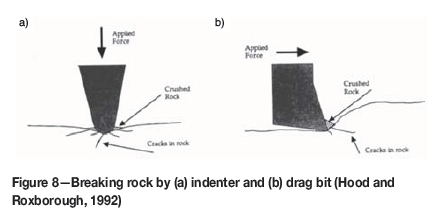
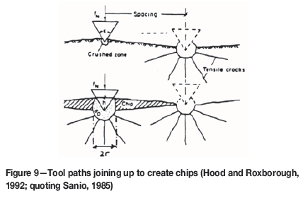
Both types ultimately break rock in tension: drag bits apply a shear force that initiates a tension crack; indenters crush rock directly below the tool and the crushed material dilates and causes tension in the surrounding rocks. In both cases, tension cracks formed in the rock link up between successive passes or tools running in parallel to create chips (Figure 9). There is considerable subtlety hidden in these simple explanations, which is detailed in Hood and Roxborough (1992) and elsewhere.
Impact breaking is a form of indenting: the tool is in compression, although the compression occurs in pulses rather than as continuous pressure.
Drag bits are more efficient at breaking rock than indenters, but are subject to considerable shear forces that generate tensile stresses in the cutter material. The face of the cutter is usually a very hard material, often tungsten carbide (WC) which is also brittle. As all brittle materials are weak in tension, tool failure is more likely in a drag bit. In an indenter, the cutting forces can be arranged to be only compressive in the tool material, greatly improving the lifetime of the tool. Today, drag bits are largely used for cutting coal and soft rock, although there are efforts to extend their range to medium strength rocks, as discussed later.
The cutting efficiency of drag bits increases with cut depth (Grant et al., 1981), and there is no significant change in efficiency with bit speed, so for a given power it is more efficient to cut slow and deep. While chisel picks cut more efficiently than pointed picks at the same depth of cut, pointed picks require lower forces, and so can cut deeper for the same force than a chisel pick. Pointed picks are therefore more efficient in general use.
In general, the fragment size of broken rock increases with increasing specific energy efficiency. This implies that any change in the system that increases cutting efficiency will also produce a coarser product. By inference, the generation of harmful dust decreases as efficiency increases.
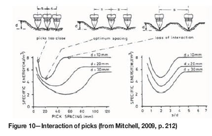
When using an array of picks, there is an optimum distance between picks (Figure 10). The optimum spacing is when each pick generates a tensile crack that joins up with the crack from an adjacent pick to create a chip. If the picks are too close, they do not generate significant chips between one-another. If they are too far apart, the cracks cannot join up.
In the corner of the excavation, a pick will not be able to interact with adjacent picks. The cutting forces increase by two to three times, leading to an increase in specific energy of three to four times compared with face picks. Cutting should be arranged so that the first pick to cut can exploit a free surface. Each following pick can then use the relief created by the first pick, until the final pick cuts in the corner. The cutting sequence should always end in the corner, and never start there (Hood and Roxborough, 1992).
Abrasion has also been used directly as a cutting method, particularly in the form of diamond wire cutting or sawing, as discussed above.
While mechanical cutting is the most common form of rock cutting in practice, a number of other techniques have been proposed for cutting rock.
Thermal breaking
Fire was one of the original methods for breaking rock, and was the primary method of breaking hard rock prior to the development of explosives. Thermal methods can be used in two ways: to melt the rock or to cause thermal spalling.
Melting requires high specific energy, so is likely to be viable only for particular applications such as drilling shotholes for explosives, and only under conditions where speed or access issues mean that other drilling techniques are not possible.
Thermal spalling occurs when thermal stress cracks the rock. When heat is applied, the temperature gradients in the rock cause stresses that extend existing micro-cracks (Ndeda et al., 2015). Not all rocks spall. The temperature gradient depends on the thermal properties of the rock, and the stresses depend on the presence of particular minerals. The presence of water is important, as is the presence of minerals that undergo phase change at higher temperatures (Zhang et al., 2010). There is experimental evidence to link spalling to the presence of quartz (Howarth and Hood, 1995).
Thermal spalling can be initiated by several sources of heat, including flames (Rauenzahn and Tester, 1989), lasers, and electropulse and hydrothermal methods. The only technique that has seen significant use is flame, used in thermal lancing to cut high-quartz granite, and as a mining method. For mining, flame is appropriate for narrow-vein deposits, particularly when the mineralized layer spalls and the host rock does not, where it is able to break mineralization selectively, greatly reducing dilution (ROCMEC, 2015). Thermal spalling also has advantages as a deep-drilling technique because the equipment does not suffer from wear as a mechanical system would, and it can potentially deliver very high drilling rates (EPRI, 2013).
Thermal spalling has been considered for deep South African mines in the past, but was disregarded as it has poor specific energy efficiency and adds substantially to the already large heat load at depth (Haase and Pickering, 1987). More recently, in 2014, South African-based Maxem licensed patents for thermal fragmentation from Rocmec (Accesswire, 2014; Maxem, n.d.) and is reporting good performance in Witwatersrand quartzite and other hard rocks, with modest diesel consumption. Maxem has also confirmed the ability to break a reef using thermal spalling without fracturing the hangingwall.
Waterjets
Waterjets can break rock directly by erosion, but as indicated in Figure 3, they are not efficient (Wilson et al., 1997). They are therefore more applicable in combined techniques, and in niche applications, for example in creating a shaped chamber in the rock for explosives or other purposes, or for drilling tight-radius curves.
It is also possible to break rock by injecting high-pressure shock waves through the water into holes drilled in the rock. A device was developed by the CSIR that could deliver pulses of water at 300 MPa through a nozzle into a water-filled hole (Frangakis, 1999). It was shown to break fractured and unfractured quartzite with burdens up to 350 mm, but required drill-holes. The equipment itself was also regarded as cumbersome and there were issues with retaining the water in the drill-holes (van der Merwe et al., 2001, p. 49).
Rock cutting today
The underground soft-rock mining and tunnelling industries, and in particular the coal mining industry, have converted almost completely to mechanized rock cutting (Mitchell, 2009) for many of the reasons outlined in the section on needs, above. Three machines dominate: the roadheader, the continuous miner, and the longwall.
The roadheader
A roadheader is a track-mounted machine with a cutting head that can be moved independently in a horizontal arc and a vertical arc. It typically has a system of gathering arms to collect muck and transfer it to a haulage system via a chain conveyor. The cutter head can be transversal as pictured in Figure 11, or longitudinal, where the cutter rotates parallel to the boom axis, as in Figure 12 (Sandvik, 1999).

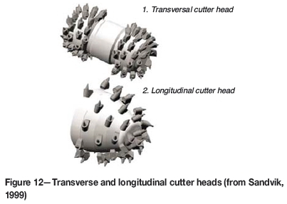
In older machines, longitudinal cutter heads dominated because of their simpler gear design, but today transverse cutter heads are more common as they have generally better performance. The reaction forces in transverse heads act directly towards the machine body, and are counteracted by the machine weight. In a longitudinal head, the reaction forces are perpendicular to the machine axis, tending to swing the machine sideways (Gehring, 2002).
Both types of roadheader allow for considerable flexibility in the profile of the excavation. Longitudinal cutter heads can produce more accurate profiles if designed for the specific application, whereas the profile accuracy of transverse cutter heads is independent of the profile (Gehring, 2002). In applications where the roadheader cannot cut the full profile of the face in a single cut, it can be applied in a series of operations to cut profiles of nearly unlimited size.
The state of the art for roadheaders is probably the Sandvik ICUTROC system, currently being marketed (Gehring and Reumiiller, 2003). The ICUTROC system includes a number of improvements over standard roadheaders (Gehring, 2002):
► Lower cutting speed: a new gearbox enables the machine to operate at a cutting speed of 1.4 m/s, rather than the previous 3 m/s. For the same power, the cutting force can therefore be doubled. In low to moderate strength rock, the lower speed greatly improves cutting efficiency. For harder and more abrasive rock, additional measures had to be added
► A new grade of tungsten carbide, the S-grade, was developed and patented in 1996, which offers twice the life over the previous generation of picks
► Wear in picks is closely related to temperature and rock abrasiveness. Temperature is controlled by high-pressure water jets at each pick that have the secondary benefit of flushing cuttings, further reducing wear. This improved cooling system halved pick wear, while also reducing the amount of flushing water by 25% (see also Hood et al., 1990; Ip et al., 1986). Water jets also suppress dust
► The new picks and cooling system were integrated using computer simulation to design cutter heads with a smooth torque balance while cutting. The aim is to ensure that pick loading remains in a non-critical range even for rocks with a UCS greater than 130 MPa
► Elasticity in a machine results in poor efficiency. The boom of the ICUTROC machine has been stabilized using a hydraulic control system, with larger boom cylinders and prestressed vertical boom cylinders
► The entire machine has been tuned to improve system stiffness, using finite element methods. The most stressed parts of the machine are reinforced.
Greimel and Owens (2010) quote good performance in hard rock from case studies. At Peñoles silver mine in Mexico, a Sandvik MH620 roadheader cut rock with an average hardness of 103 MPa, but including quartz veins up to 300 MPa, at 24 solid m3/h with pick consumption of 0.3 picks per solid m3. Pichler et al. (2010) quote impressive figures achieved during enlarging of the Mont Cenis tunnel under the Alps. The rock was calcareous schist, partly quartzitic with quartz layers 1-10 cm thick. A Sandvik MT620 averaged 83 m/d on the second rail with a best rate of 240 m/d. Pick consumption was about 0.1 picks per solid m3 of cut material, and a total of 27 815 m3 of rock was excavated.
While the results quoted above are good for hard rock, ICUTROC and roadheaders are still not universally applicable in all rock types. In most of the published case studies, abrasiveness is low to medium. In one South African trial, Pickering and Ebner (2002) quote results from cutting UG2 Reef, largely consisting of chromitite. The strength was modest, at just 26 MPa, but the Cerchar Abrasiveness Index was very high at 5.4. The picks were damaged severely after only four passes over the UG2. The experience convinced the authors that pick cutting was not suitable for that application.
The continuous miner
A continuous miner (CM) is a tracked machine with a single drum cutter than can be moved in a vertical arc, in a similar manner to a transverse cutter roadheader, but without the capacity to swing the drum horizontally. The drum covers the full width of machine and operates above gathering arms that load the coal through the machine onto a conveyance (Figure 13). CMs are in common use in coal and potash mines as well as other types of soft-rock mines.

The typical cycle is to move the CM into the face with the drum rotating and raised to touch the roof. This operating is called sumping. The cutter then moves downward, cutting coal in an action called shearing. Finally, the machine is reversed to clean the floor. Due to the geometry of the drum, a CM can only cut a rectangular profile. If the desired profile is wider than the machine, the machine must be repositioned for a second cut.
From a cutting point of view, CMs are very similar to roadheaders. They use drag bit cutters, designed to match the characteristics of the material that they are working in. The art of designing the pattern of picks is also the key to obtaining efficiency (Hekimoglu and Ozdemir, 2004).
The longwall
A longwall is a configuration of machinery for continuously producing coal at a very high rate. The system consists of an armoured face conveyor, or AFC, running the full length of the face between two access roads, or gates. The face is anywhere from 100 m to more than 300 m in length. The shearer runs on the AFC, typically with two cutting heads. After cutting, coal falls onto the AFC and is conveyed to one of the gates using a scraper chain conveyor. Behind the AFC in the mined-out area is a line of powered roof supports called chocks. As mining progresses, the chocks push the AFC forward, then pull themselves forward. Behind the chocks, the roof collapses or goafs under its own weight.
From the point of view of cutting, the shearer drum is similar to a CM cutter or a cutter head on a roadheader. It is typically larger, slower rotating, and powered by a very powerful motor to ensure that it is able to cut quickly and is not stopped by hard coal or thin bands of rock in the coal. The state-of-the-art shearer today will weigh up to 100 t, have a cutting power of up to 1 MW per shearer (Mitchell, 2009), and will produce coal at a rate of about 500 000 t/ month or more.
Full-face rock cutting
When the rock becomes too hard for picks, the alternative is to use indenters. Indenters are often used in full-face cutting, including TBMs, raiseborers, and other similar tools.
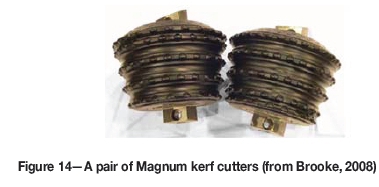
The original TBM tool was the disc cutter, as used in the Robbins machine of 1956 where discs replaced picks for the first time (Hapgood, 2004). Today, the demands of larger cutters and harder materials are leading to less use of discs, and increased use of kerf cutters that consist of a series of 'discs' mounted in a single cutter. The kerfs are usually impregnated with WC inserts to improve performance in hard rock (Figure 14).
There are variations on the kerf theme that provide different performance, in cuttings removal, wear, drilling rate, and torque in various rock types. Carbide rowed cutters and random insert cutters have the WC inserts placed directly on the surface of the drum and not on raised kerfs (Figure 15).
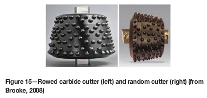
Kerf, rowed, and random cutters require fewer bearings than disc cutters, where each cutter requires its own bearing. The insert spacing and angles on rowed and random cutters are set to reduce tracking - where a particular insert lands in the crater formed by a previous insert. Random cutters are particularly efficient, producing a new pattern with every pass of the cutter (Brooke, 2008).
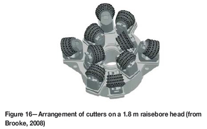
In Figure 16, ten cutters are arranged on a head to cover the whole face of a raise. In order to reduce wear in hard rock, the cutters are arranged so that the whole cone rolls over the surface of the rock. If the cutting elements skid, the wear rate increases dramatically. However, in softer rock, an element of skid can reduce the forces required to break the rock (Hood and Roxborough, 1992, p. 702). The detailed design of the head depends on the application.
Rolling cutters are applied in a number of full-face configurations. A TBM uses a mechanical gripper system to hold itself against the walls of the tunnel and so provide the thrust forces for the cutter. In mining, smaller holes are excavated using a variety of configurations, of which raiseboring is the most established (Sandvik, 1999).
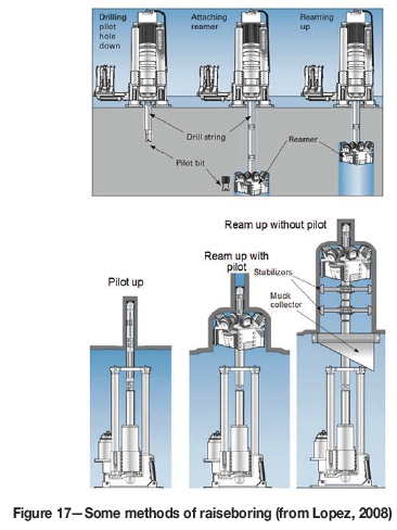
In raiseboring, a pilot hole is first drilled, which is then reamed by pulling a full-face cutter up along the line of the pilot hole. Thrust forces are provided through tension on the drill string. In blind boring, the machine drives the cutting head forward by pushing on the drill string. There are a number of combinations of pushing or pulling, with or without a pilot hole, some of which are illustrated in Figure 17. While the machines change, for hard rock the basic cutting mechanism remains indentation with WC inserts of some type. Hard-rock TBMs use the same range of cutters and design techniques.
Full-face hard-rock TBMs have been used on mines for tunnel development, with mixed results (Cigla et al., 2001). The large size, high weight, and long setup time work against the TBM as a flexible mining tool. There are also issues with the round tunnel shape, because mines usually require a flat-bottomed tunnel, and the lack of flexibility for installing support. Where the requirement is for fast, long and mostly straight development, a TBM is ideal, and has been highly successful in very hard rock at Stillwater mine in Montana, USA (Brox, 2013). For a thorough reference on TBM use in mining, see Zheng et al. (2014).
TBMs have been used in a number of trials in South Africa. Anglo American Corporation ran trials with a Wirth machine at Free State Geduld mine, where the machine drilled 1150 m over 28 months (Taylor et al., 1978); at Vaal Reefs, where it covered just 494 m of a planned 2.4 km tunnel; and at President Steyn, where it covered 656 m in about a year (Marlowe et al., 1983). The systems experienced problems with cutter heads, muck-handling, and adapting to bad ground conditions where large rocks were encountered. Similar issues plagued a trial at Libanon Gold Mine (Pickering et al., 1999). TBMs did prove capable of cutting Witwatersrand quartzite, and the trials showed that boring with a TBM in stressed rock results in much better rock conditions than in blasted tunnels because the fracturing associated with blasting is avoided.
A TBM was also used at Anglo American Platinum's BRPM North Shaft. It drilled only 340 m over six months at an average of 0.47 m/h, with just 22% utilization, but the trial did prove the concept of using a TBM for platinum development. The majority of problems encountered were typical of a new machine in a new environment, and were not fundamental; issues such as maintenance, difficulty clearing muck, and steering the machine. The cutter life was much better than expected at 12.2 m3 of rock per ring (Stander et al., 2001). Stander concludes that the project was 'a success, notwithstanding the deficiencies of a TBM manufactured in 1972' and 'there is no reason why significant development cannot be carried out in the future with TBMs on narrow reef platinum mines.'
Hybrid technologies
There have been a number of attempts to combine the indent cutting of a TBM with the mobility and flexibility of a roadheader or other small machine.
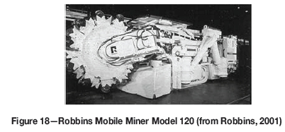
The concept of the Robbins Mobile Miner is a relatively thin rotating wheel with disc cutters on its periphery, capable of cutting hard rock. Since only a few cutters engage the face at a time, the machine can be relatively light, mobile, and less capital-intensive than a TBM (Sugden and Boyd, 1988).
The first Robbins Mobile Miner was ordered by Mt. Isa Mines in 1983 (Figure 18). The design incorporates disc cutters mounted on the rim of a cutting wheel, with the intention that loads on the cutters would be similar to those in a TBM. The machine completed 1.75 km in hard rock consisting of strong and highly abrasive quartzites and greenstones with UCS values from 210 MPa to 420 MPa. The machine showed potential, but also exposed the limits of its first-generation design in terms of cutter costs, rigidity, and reliability (Dahmen and Willoughby, 1995).
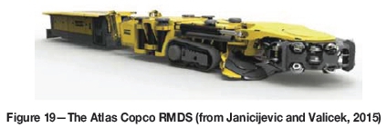
An improved model, the MM130, was developed but was discontinued in 1998 (Atlas Copco, 1998) after Atlas Copco acquired Robbins in 1993. Robbins (2001) describes it as an example of a machine 'that did not make it', despite proving the technology. Atlas Copco has since announced developments based on technology learning from the Robins Mobile Miner (Atlas Copco, 2010; Janicijevic and Valicek, 2015). The company has also announced the Rapid Mine Development System (RMDS), which uses a similar disc cutter system to the Mobile Miner, but runs the cutter head horizontally rather than vertically. It resembles a TBM, but cuts a rectangular-shaped tunnel and provides the flat floor required by mechanized machines. It has not yet undergone trials.
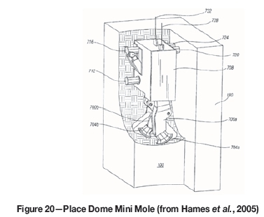
A similar semi-full-face machine, the Mini Mole, which uses undercutting disc cutters, was developed by Placer Dome (Hames et al., 2005). It was designed for near-vertical narrow-vein hard-rock deposits (Figure 20). According to Janicijevic and Valicek (2015), it was initially successful, but later lost managerial support and was ultimately abandoned.
A descendant of the Mini Mole, the RM850 Reef Mole, was tested at the Townlands shaft of Anglo Platinum (Janicijevic and Valicek, 2015). The trial was stopped due to geological undulations and a successor machine, the RM950, was developed. Design and assembly problems stalled the project, after which the supplier and Anglo Platinum suspended the project on funding grounds (Janicijevic and Valicek, 2015).
Reef borers
There is no routine production today from rock cutting in South African underground hard-rock mines. Some of the current development is occurring around the use of boring techniques to mine the narrow stopes.
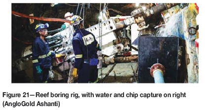
AngloGold Ashanti (AGA) has been running a Technology Innovation Consortium for a number of years with the aim to mine 'all the gold, only the gold, all the time'. The company has investigated various technologies but the experimental focus has been on reef coring (Figure 21). Perhaps the best account of the progress is in AGA's 2015 annual report (AGA, 2015). In 2015 AGA started testing the fourth generation of their reef-boring machine, and is moving towards its routine use in the future.
In reef boring a hole is bored through the reef from gully to gully, typically using raiseboring technology. After one hole has been drilled, the rig is moved to the next hole but one. All holes are then backfilled, and the rock remaining between the holes is drilled and backfilled. The relatively small holes and the rapid backfilling after drilling are intended to impose as little stress as possible on the rock, and so minimize fracturing and seismic events.
AGA has introduced a range of machines of different sizes and for different applications (AGA, 2015). Rock chips created by the drilling process are flushed directly into a collector bin, and transported by pipe to a carrying car. The closed nature of the collection system should reduce gold losses.
Anglo American Platinum is developing a similar tool, known as a slot borer. It is also based on raiseboring technology and uses TBM-style steel discs. The system is expected to go underground shortly for proof-of-concept trials (Janicijevic and Valicek, 2015). The rock collection system is pneumatic rather than hydraulic, to minimize water-related problems with the platinum ore.
The future
In this section, a selection of promising techniques that can advance rock cutting is discussed. The list is not comprehensive, and is selected largely on the basis of relative maturity, significant investment, and current interest.
Undercutting
Two adaptations of conventional cutting technology stand out as having great promise for the future. The first is undercutting.
In conventional disc cutting, the disc acts to apply a compressive stress to the rock. If the angle of attack of the disc is changed to be similar to that of a drag bit, the action becomes undercutting (Figure 22).
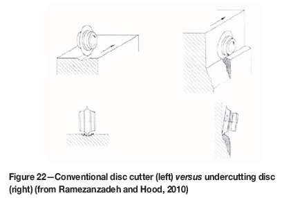
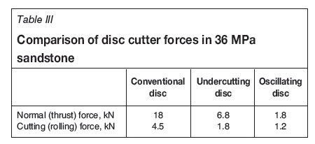
Undercutting directly creates tensile stresses, so it operates with lower forces and lower specific energy. In one example, a test at CRC Mining in Brisbane (detailed in the first two columns of Table III which compare the normal and rolling forces in conventional and undercutting for the same disc in a 36 MPa sandstone), showed the forces to be reduced by about 2.5x when undercutting (Ramezanzadeh and Hood, 2010).
Because the disc rotates, it is able to distribute the heat load better than a drag bit, but undercutting does suffer from the bending load experienced by drag bits, which might limit the strength of rock that can be cut.
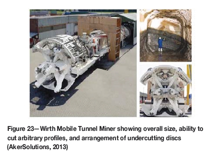
AnkerSolutions and Sandvik have developed machines that exploit undercutting. The AnkerSolutions Wirth MTM 4 uses a number of arms with undercutting discs on them (AkerSolutions, 2013). Compared to a TBM, it has a much smaller turning circle of down to 12 m, and can cut a large variety of tunnel profiles. The minimum tunnel size of the MTM 4 is 5.1 m (Figure 23). AnkerSolutions has also developed a machine called a Tunnel Boring Extender (TBE) to widen tunnels. It uses undercutting and is claimed to be energy-efficient, but it does require a pilot tunnel (Ramezanzadeh and Hood, 2010).
The Voest-Alpine Sandvik Reef Miner, the ARM 1100, was developed for the South African platinum mines (Figure 24). It has been tested on the Merensky and UG2 reefs. The Merensky is stronger, at 150 MPa to 200 MPa UCS, while the UG2 varies from 40 MPa to 120 MPa but is very abrasive, containing minerals with Mohs hardess values of 5 to 6. The Merensky was easier to cut due to its brittle nature.
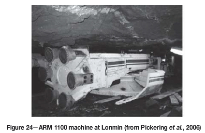
On an extensive set of trials between 2002 and 2005, the machine cut more than 7 200 m3 in South Africa, in addition to other trials in a Polish copper mine (Pickering et al., 2006). According to Ramezanzadeh and Hood (2010), the cutter cost was excessive. Trials did not continue after 2006, but Sandvik has further developed the technology in light of the lessons learned and implemented it in the MN220 Reef Miner. This machine passed its proof-of-concept targets, and is currently being optimized (Janicijevic and Valicek, 2015).
Oscillation/activation
The other technology that is currently in development to extend the range of disc-type cutters is activation.
The principle is to add an eccentricity to the disc cutter as it undercuts. The technology, from CRC Mining, is known as oscillating disc cutting (ODC) and is being commercialized by Joy Global under the tradename Dynacut, (Hood and Alehossein, 2000). The effect of adding a small oscillation with a frequency of 35 Hz to an undercutting disc is shown in the last column of Table III. Both the normal and cutting forces are reduced considerably compared with those of the undercutting cutter without oscillation.
A first-generation ODC was trialled at Bathopele platinum mine. Although it missed its key performance indicator targets, it provided invaluable experience and knowledge (Janicijevic and Valicek, 2015). The technology is maturing. A second-generation machine, the HRCM10, has started underground trials in a South African platinum mine (Figure 25).

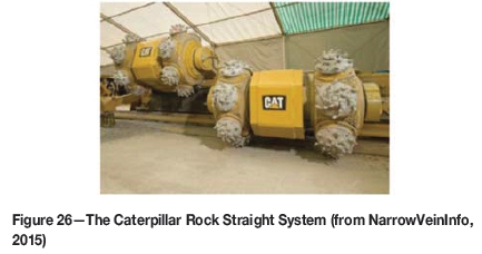
Bechem (Lenzen and Bechem, 1989) patented an alternative activation technology called Activated Disc Cutting or the Activated Disc System, that was tested at Townlands from 2007. It used drag picks, but was unsuccessful due to recurring reliability issues (Janicijevic and Valicek, 2015). The technology later became known as 'activated undercutting'. It was licensed to Bucyrus, now part of Caterpillar, who have called it the Cat Rock Straight System. A single photograph (Figure 26) of the system appeared on the Narrowvein website, with links to Caterpillar official pages that were deleted shortly afterwards. The Narrowvein site itself is now also gone, but its Twitter record remains (NarrowVeinInfo, 2015).
Improved cutters
Drag bits are more efficient than indenters, but they are also subject to higher tensile and shear forces, as discussed above. To broaden the applicability of drag bits, new materials are required. Polycrystalline diamond composite (PDC) is widely used in the gas and oil industry, but it is limited to temperatures below 750°C (Ramezanzadeh and Hood, 2010). At higher temperatures, the cobalt binder in the diamond composite acts as a catalyst to convert the diamond to graphite. In cutting in abrasive rocks, temperatures of 1300°C have been observed at the cutting interface, to the point that a thin film of molten rock has been observed in the groove.
Thermally stable diamond composites (TSDCs) either use a silicon carbide matrix or leach the cobalt out of the matrix to avoid the temperature limitation. Varieties of TSDC have shown stability at 1200°C and above. A nanostructured diamond-silicon carbide composite has been patented that has excellent fracture toughness while maintaining diamondlike wear resistance, and further research into nanomaterials is continuing (Boland and Li, 2010).
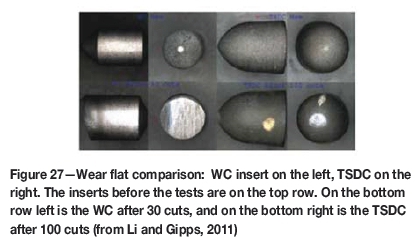
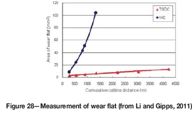
Apart from resistance to temperature, the other challenge for producing TSDC picks is bonding the cutting element to the pick body. CSIRO has developed a patented bonding method as part of its SMART*CUT technology (Alehossein and Boland, 2004). The inserts have exceptional wear resistance. In Figure 27, one measure of wear resistance is illustrated: the size of the wear flat on a WC insert, compared to that on a TSDC insert, after the tools were applied to a corundum grinding wheel. Figure 28 shows the size of the wear flat compared to the cutting distance.
SMART*CUT picks have cut rock as hard as 260 MPa in the laboratory. Today, they will usefully extend the usage range of drag bit cutters such as roadheaders into more abrasive materials. With further development using nanoma-terials, roadheaders may be able to cut economically in any rock type.
Combined methods
For the hardest and most abrasive rocks, mechanical cutting will struggle if it continues to depend on the materials currently available. There have been a number of suggestions for improving cutting efficiency by pre- or co-treating the rock in some way. Possibly the easiest to implement are the laser and high-pressure water methods.
Laser
Rad and McGarry (1970) tested a 750 W carbon dioxide-nitrogen-helium laser, in conjunction with a drag bit, to cut Barre Granite with a UCS of 220 MPa. They found that the laser decreases the specific energy and increases the amount of muck per cut. Ndeda et al. (2015) present a good review of laser methods as a starting point for interested researchers.
High-pressure water
Waterjets are already in use on CMs to flush out crushed rock and reduce energy use. There is almost certainly more scope for investigating the use of high-pressure water to improve rock cutting, in a similar manner to that reported by Pederick and Lever (2004) for blast-hole drilling.
Thermo-hydraulic
Rather than combining another tool with mechanical rock-breaking, Thirumalai and McNary (1973) suggest combining heat and water by applying high-pressure water after heating the rock. If the rock is heated, the specific energy required by the hydraulic method reduces by about an order of magnitude. The water pressure and laser power used are considerable, but this method might still be worth revisiting.
Automation
Apart from improvements to the cutting method, there are many efforts to improve cutting performance using automation. As long ago as 1992, Shaffer and Stentz published a paper on CM automation in which they successfully extended a coal mine bord by 'several feet' by automatically executing a series of cuts (Shaffer and Stentz, 1992).
The Robbins Mini Miner is also reported to have been regularly left operating by itself (Robbins, 2001), although its control system was not automated. Running without supervision, the Mini Miner was able to improve its advance rate.
All the major suppliers of mining equipment now include some level of automation, improving machine accuracy and operator efficiency and allowing for continued operation when people are withdrawn from the mine during the blast period.
Conclusion
In this paper, some of the history and background of rock cutting have been discussed, and some current and future techniques examined. Returning to the issue of engineering knowledge raised in the introduction, the processes of variation and selection can be seen at work.
In coal and soft rock, several different variations on cutting systems and machine designs have been attempted, but the final selection is clear: longwall mining systems where they can be deployed, and continuous miners where more flexibility is required or where a longwall cannot fit the geometry.
There is no parallel consensus yet for hard-rock cutting. Developing new technology for rock breaking is very challenging.
► Apart from the technology itself, all technical innovations come about through processes that are entirely social: 'persuasion, negotiation, personal and professional interests, network building and ally recruitment, and corporate and institutional power [my emphasis] (Constant, 1994)
► According to Robbins (2001), the development of the Robbins Mini Miner cost about $50 million. 'It has served to illustrate that the cost and time required to develop this type of machinery is often much greater than could have been expected by the developers'
► Wilson et al. (1997) extend the issue of economics. They describe how in the original conference on high-pressure waterjets in 1972, nearly half the papers were on mining applications. At the conference in 1994, only 11% were on mining applications. They blamed the drop in interest on the small relative size of the mining market, and the need to solve the technical problems outside of the mining field
► In technological change, there is always pressure to remain with the status quo (Constant, 2002)
► In South African gold and platinum mines the rock is hard and abrasive. Mining-induced fracturing can help, but it cannot be assumed to be present. Any successful method will need to be able to break even the hardest and most abrasive rock types, as well as handle the large rocks produced by mining-induced fracturing.
There is a repeated refrain in the case studies presented here about maturity and learning. Successful hard-rock breaking is something new and requires learning. As we see the new generations of particular cutting machines in trials, we recognize that technology does not mature without learning.
The key issues for mining machines in the real world go beyond the pure ability to cut rock, and include the need to follow the unpredictable orebody. Perhaps the major non-cutting challenge is how to move rock effectively away from the cutter. Several of the machines reviewed here were successful at cutting, but failed as systems because the rock transport solution was insufficiently developed
While disc cutters can break the hardest and most abrasive rock, only a conceptual breakthrough is going to provide the cutting tool that will fit into an ideal system for narrow-reef hard-rock mining: efficient, small, light, and flexible compared to current systems.
Producing the breakthrough is going to take courage to challenge the status quo; it is going to take more money that anyone expects, and is going to take time. In most markets, the developers of a new product can take a risk based on the size of the prize. In mining, the prize goes to the miner, not the product manufacturer. There is a need for the miner and developer to enter into a fair partnership around risk and reward. The current low commodity prices may act as the spur to make the breakthrough, ironically by making the funds available to compensate for the small size of the market.
Which technology will win out is open - as Nils Bohr said, 'Prediction is very difficult, especially if it is about the future'.
Acknowledgements
Five companies fund the Centre for Mechanised Mining Systems in 2016: African Rainbow Minerals, Anglo American Platinum, Hatch, Joy Global, and Worley Parsons. Their support is essential for the successful operation of the Centre, and is gratefully acknowledged. I also thank an anonymous reviewer for comments that have greatly strengthened this paper.
References
Accesswire. 2014. Rocmec signs an exclusive Thermal Fragmentation distribution agreement with MaXem Equipment (Pty) Ltd. of South Africa. https://www.accesswire.com/viewarticle.aspx?id=412291 (accessed 28 September 2016). [ Links ]
AGA. 2015. Anglogold Ashanti Integrated Report 2015. Anglogold Ashanti. AkerSolutions. 2013. Wirth Mobile Tunnel Miner. [ Links ]
Alehossein, H. and Boland, J. 2004. Diamond composite cutters in drill bits and cutting tools for hard rock cutting. Proceedings of EXPLO 2004, Perth, Western Australia. Australasian Institute of Mining and Metallurgy, Melbourne. pp. 47-55. [ Links ]
AsHMOLE, I. and Motloung, M. 2008. Dimension stone: the latest trends in exploration and production technology. Proceedings of Surface Mining 2008. Southern African Institute of Mining and Metallurgy, Johannesburg. pp. 35-70. [ Links ]
ATLAS COPCO. 2010. Atlas Copco and Rio Tinto to explore advanced tunneling equipment for deep underground mines. http://www.atlascopco.co.za/zaus/news/corporatenews/100224_rio_tinto_select s_atlas_copco_mmm.aspx (accessed 21 July 2015). [ Links ]
Atlas Copco. 1998. Restructuring of the mechanical boring business. http://www.atlascopco.co.za/zaus/news/corporatenews/restructuring_of_the_ mechanical_boring_machine_business.aspx (accessed 21 July 2015). [ Links ]
Barnatt, J., Rieuwerts, J., and Haddon Thomas, G. 1997. Early use of gunpowder in the Peak District: Stone Quarry Mine and Dutchman Level, Ecton, Derbyshire. Mining History Bulletin of the Peak District Mines Historical Society, vol. 13. pp. 24-43. [ Links ]
Barnes, R.E. 1969. Discussion on: Rock-cutting and its potentialities as a new method of mining. Journal of the South African Institute of Mining and Metallurgy, vol. 69. pp. 50-51. [ Links ]
Bieniawski, R.Z.T. 1989. Engineering Rock Mass Classifications: a Complete Manual for Engineers and Geologists in Mining, Civil, and Petroleum Engineering. Wiley. [ Links ]
Bieniawski, R.Z.T., Celado, B., Tardaguila, I., and Rodrigues, A. 2012. Specific energy of excavation in detecting tunnelling conditions ahead of TBMs. Tunnels & Tunnelling International, February 2012. pp. 65-68. [ Links ]
Boland, J. and Li, X.S. 2010. Microstructural characterisation and wear behaviour of diamond composite materials. Materials 2010. pp. 1390-1419. doi:10.3390/ma3021390 [ Links ]
Brooke, S. 2008. Cutter and reamer design. Raiseboring in Mining and Construction. Atlas Copco Rockdrills AB, Örebro, Sweden. pp. 56-63. [ Links ]
Brox, D. 2013. Technical considerations for TBM tunneling for mining projects. Transactions of the Society for Mining, Metallurgy and Exploration, vol. 334. pp. 498-505. [ Links ]
Carter, R.P. 1997. The application of diamond wire mining at Saaiplaas No. 5 Shaft. Association of Mine Managers, Papers and discussions: 1994-1996. pp. 236-291. [ Links ]
Cigla, M., Yagiz, S., and Ozdemir, L. 2001. Application of tunnel boring machines in underground mine development. Proceedings of the 17th International Mining Congress and Exhibition of Turkey. Chamber of Mining Engineers of Turkey. [ Links ]
Constant, E.W. 2002. Why evolution is a theory about stability: constraint, causation, and ecology in technological change. Resource Policy, vol. 31. pp. 1241-1256. [ Links ]
Constant, E.W. 1994. Comment on 'The Retractable Airplane Landing Gear and the Northrop 'Anomaly.'' Technology and Culture, vol. 35. pp. 447-449. doi:10.2307/3106335 [ Links ]
Cook, N.G.W. 1970. Continuous hard-rock breakage and its potential effect on deep-level mining. Transactions of the Society of Mining Engineers, vol. 247. pp. 1-4. [ Links ]
Cook, N.G.W. 1969. Continuous hard rock breakage and its potential effect on deep-level mining. Annual Meeting of the American Institute of Mining, Metallurgical and Petroleum Engineers, Washington, DC. Preprint 69-AU-39. [ Links ]
CRC Mining. Not dated. Oscillating disc cutter (ODC). [ Links ]
CROLL, A.M. 2004. Mechanization - an Anglo Platinum perspective. Proceedings of the International Platinum Conference: 'Platinum Adding Value', Sun City, South Africa. Southern African Institute of Mining and Metallurgy, Johannesburg. pp. 125-142. [ Links ]
Dahmen, N. and Willoughby, R. 1995. Recent mobile miner developments. SME Annual Meeting, Denver, Colorado. Preprint 95-115. [ Links ]
Drinker, H.S. 1882. Tunneling, Explosive Compounds, and Rock Drills. Wiley, New York. [ Links ]
Dunn, P.G. 1989. The non-explosive mechanisation of the South African gold mine stoping operation. Masters disssertation, University of the Witwatersrand, Johannesburg. [ Links ]
EPRI. 2013. Technology Insights Brief: Potter drilling hydrothermal spallation. Electric Power Research Institute, Palo Alto, California. [ Links ]
Fenn, O. and Marlowe, A.C. 1990. Non-explosive mechanized stoping: the challenge. Proceedings of the International Deep Mining Conference: Technical Challenges in Deep Level Mining. South African Institute of Mining and Metallurgy, Johannesburg. pp. 743-754. [ Links ]
Frangakis, T.J. 1999. The development and testing of a water-pulse rock breaking system. Proceedings of Telemin 1 and the 5th International Symposium on Mine Mechanization and Automation, Sudbury, Ontario. Miller. [ Links ]
GEHRING, K.H. 2002. Roadheader. Politecnico di Torino, Torino. [ Links ]
Gehring, K.H. and Reumiiller, B. 2003. Hard rock cutting with roadheaders the Icutroc approach. 2003 Tunnelling Association of Canada Annual Publication. [ Links ]
Gong, Q.M. and Zhao, J. 2007. Influence of rock brittleness on TBM penetration rate in Singapore granite. Tunnelling and Underground Space Technology, vol. 22. pp. 317-324. [ Links ]
Grant, I.L., Pieterse, J.Z.C., and Phillips, H.R. 1981. Coal cutting using chisel picks. Research Report no. 11/82. Chamber of Mines of South Africa Research Organisation. [ Links ]
Greimel, C. and Owens, K. 2010. Applications and use of roadheaders in rock environment beyond 100 MPa hardness. Proceedings of the MEMO CIM Conference, Sudbury, Ontario. CIM, Montreal. [ Links ]
Haase, H.H. and Pickering, R.G.B. 1987. The status of non-explosive mechanized mining in narrow reefs. Research Report no. 5/87. Chamber of Mines of South Africa Research Organisation, Johannesburg. [ Links ]
Hames, M.P.A., Dimock, T.B., Anwyll, E.W.D., Young, D.D., Delabbio, F.C., Jackson, E., and Jackson, S.M. 2005. Mining method for steeply dipping orebodies. US patent US6857706 B2. [ Links ]
Hansen, A.M. 1998. The history of TBM tunnelling in Norway. Norwegian TBM Tunnelling. Norwegian Soil and Rock Engineering Association. [ Links ]
Hapgood, F. 2004. The underground cutting edge: the innovators who made digging tunnels high-tech. American Heritage of Invention and Technology, vol. 20. pp. 42-48. [ Links ]
Hekimoglu, O.Z. and Ozdemir, L. 2004. Effect of angle of wrap on cutting performance of drum shearers and continuous miners. Mining Technology, vol. 113. pp. 118-122. [ Links ]
Hojem, J.P.M., Joughin, N.C., and Dimitriou, C. 1971. The design and development of a rockcutting machine for gold mining. Journal of the South African Institute of Mining and Metallurgy, vol. 71. pp. 135-147. [ Links ]
Hood, M. 1976. Cutting strong rock with a drag bit assisted by high-pressure water jets. Journal of the South African Institute of Mining and Metallurgy, vol. 76. pp. 79-90. [ Links ]
Hood, M. and Alehossein, H. 2000. A development in rock cutting technology. International Journal of Rock Mechanics and Mining Sciences, vol. 37. pp. 297-305. [ Links ]
Hood, M., Knight, G.C., and Thimons, E.D. 1990. A review of water-jet-assisted rock cutting. Information Circular 9273. US Bureau of Mines. [ Links ]
Hood, M. and Roxborough, F.F. 1992. Rock breakage: mechanical. SME Mining Engineering Handbook. Society for Mining, Metallurgy and Exploration, Littleton, Colorado. pp. 680-721. [ Links ]
Hoover, H.C. and Hoover, L.H. 1950. Georgius Agricola - De Re Metallica. Translated from the First Latin Edition of 1556. Courier Corporation. [ Links ]
Howarth, D.F. and Hood, M. 1995. Potential impact of alternative rock excavation technologies on mine performance. Proceedings of EXPLO '95, Brisbane, Australia. Australasian Institute of Mining and Metallurgy, Melbourne. [ Links ]
Hughes, H.M. 1972. Some aspects of rock machining. International Journal of Rock Mechanics and Mining Sciences, vol. 9. pp. 205-211. [ Links ]
International Society for Rock Mechanics (ISRM). 1980. Basic geotechnical description of rock masses. International Journal of Rock Mechanics and Mining Sciences and Geomechanics Abstracts, vol. 18, no. 1. pp. 85-110. [ Links ]
Ip, C.K., Johnson, S.T., and Fowell, R.J. 1986. Water jet rock cutting and its application to tunnelling machine performance. Proceedings of the 27th US Symposium on Rock Mechanics (USRMS), Tuscaloosa, Alabama. American Rock Mechanics Association. pp. 883-890. [ Links ]
Jager, A.J. and Turner, P.A. 1986. The influence of geological features and rock fracturing on mechanized mining systems in South African gold mines. Gold 100 - Proceedings of the International Conference on Gold.. South African Institute of Mining and Metallurgy, Johannesburg. pp. 89-103. [ Links ]
Jager, A.J., Westcott, M., and Cook, N.G.W. 1975. A geological assessment of the applicability of reef boring to mining the Basal, Carbon Leader, and Vaal Reefs. Research Report no. 20/75. Chamber of Mines of South Africa Research organisation, Johannesburg. [ Links ]
Janicijevic, D. and Valicek, P. 2015. A review of hard-rock cutting equipment technology development at Anglo American and Anglo Platinum. Proceedings of MPES 2015, Mine Planning and Equipment Selection 2015, 'Smart Innovation in Mining, Sandton Convention Centre, Johannesburg, South Africa. Southern African Institute of Mining and Metallurgy, Johannesburg. pp. 455-468. [ Links ]
Joughin, N.C. 1978. Progress in the development of mechanized stoping methods. Journal of the South African Institute of Mining and Metallurgy, vol. 78. pp. 207-217. [ Links ]
Joughin, N.C. 1976. Potential for the mechanization of stoping in gold mines. Journal of the South African Institute of Mining and Metallurgy, vol. 76. pp. 285-300. [ Links ]
Kahraman, S., Fener, M., and Kozman, E. 2012. Predicting the compressive and tensile strength of rocks from indentation hardness index. Journal of the Southern African Institute of Mining and Metallurgy, vol. 112. pp. 331-339. [ Links ]
Lenzen, D. and Bechem, P. 1989. Activated rock cutting assembly. US patent US4815543A. [ Links ]
Leon, R.N., Salamón, M.D.G., Davies, A.W., and Davies, J.C.A., 1995. Report of the Commission of Inquiry into Safety and Health in the Mining Industry. Department of Mineral Resources, South Africa. [ Links ]
Li, X.S. and Gipps, I. 2011. Rock cutting tool research and development for step changes in rock mechanical excavation. Proceedings of the Second International Future Mining Conference, Sydney, New South Wales. Australasian Institute of Mining and Metallurgy, Melbourne. [ Links ]
Lopez, R. 2008. The raiseboring concept. Raiseboring in Mining and Construction. Atlas Copco Rockdrills AB, Örebro, Sweden. pp. 10-12. [ Links ]
MacGregor, I.M., Baker, R.H., and Luyckx, S.B. 1990. A comparison between the wear of continuous miner button picks and the wear of pointed picks used in South African collieries. Mining Science and Technology, vol. 11, no. 2. pp. 213-222. [ Links ]
Madi, B., Schmid, L., Ritz, W., and Herrenknecht, M. 2008. Hardrock Tunnel Boring Machines. Ernst und Sohn, Berlin. [ Links ]
Marlowe, A.C., Littleford, I., and Grun, M. 1983. Tunnel boring in South African gold mines. Proceedings pf the Rapid Excavation and Tunneling Conference (RETC). Society for Mining, Metallurgy and Exploration, Littleton, CO. pp. 769-801. [ Links ]
Maxem, N.D. Contracting I Maxem. http://www.maxem.co.za/contracting (accessed 28 September 2016). [ Links ]
Mitchell, G.W. 2009. Longwall mining. Australasian Coal Mining Practice. Australasian Institute of Mining and Metallurgy, Melbourne. pp. 340-375. [ Links ]
Morrell, R.J., Larson, D.A., and Swanson, D.E. 1986. Large-scale laboratory drag cutter experiments in hard rock. Report of Investigations no. 9003. US Bureau of Mines. [ Links ]
Mulgrew, I. 2015. South African growth. SRK Consulting: 40 Years in the Deep End. SRK Consulting, Johannesburg. pp. 68-100. [ Links ]
NARROWVEININFO. 2015. Cat Rock Straight System with hard rock cutting technology. https://twitter.com/narrowveininfo/status/553647660184264704 (accessed 11 April 2016). [ Links ]
Ndeda, R., Sebusang, S.E.M., Marumo, R., and Ogur, E.O. 2015. Review of thermal surface drilling technologies. Proceedings of the Sustainable Research and Innovation (SRI) Conference, Jomo Kenyatta University of Agriculture and Technology, Kenya School of Monetary Studies, Nairobi, Kenya. [ Links ]
Nicoll, A. 1976. Comment on potential for the mechanization of stoping in gold mines. Journal of the South African Institute of Mining and Metallurgy, vol. 76. p. 305. [ Links ]
Nobel, A. 1868. Improved explosive compound. US patent 78317. [ Links ]
Pederick, S. and Lever, P. 2004. Increased flexibility using waterjet assisted blasthole drilling. Proceedings of EXPLO2004, Perth, Western Australia. Australasian Institute of Mining and Metallurgy, Melbourne. pp. 57-61. [ Links ]
Pichler, J., Lammer, E., and Bertignoll, H. 2010. Innovative roadheader technology for safe and economic tunnelling. Technology Innovation in Underground Construction. CRC Press/Balkema. pp. 315-333. [ Links ]
Pickering, R.G.B. and Ebner, B. 2002. Hard rock cutting and the development of a continuous mining machine for narrow platinum reefs. Journal of the South African Institute of Mining and Metallurgy, vol. 102. pp. 19-23. [ Links ]
Pickering, R.G.B., Smit, A., and Moxham, K. 2006. Mining by rock cutting in narrow reefs. Proceedings of the International Platinum Conference -'Platinum Surges Ahead', Sun City, South Africa, 8-12 October 2006. Symposium series S45. Southern African Instititue of Mining and Metallurgy, Johannesburg. pp. 221-230. [ Links ]
Pickering, R.G.B., Watson, I.C., Klokow, J.W., and Knoetze, A.F. 1999. Practical feasibility of using TBMs in deep level gold mines. Proceedings of the Rapid Excavation and Tunneling Conference 1999. Society for Mining, Metallurgy and Exploration, Littleton, CO. pp. 981-992. [ Links ]
Plinninger, R.J. and Restner, U. 2008. Abrasiveness testing, quo vadis? - a commented overview of abrasiveness testing methods. Geomechanik und Tunnelbau, vol. 1, no. 1. pp. 61-70. doi:10.1002/geot.200800007 [ Links ]
Rad, P.F. and McGarry, F.J. 1970. Thermally assisted cutting of granite. Proceedings of the 12 th US Symposium on Rock Mechanics (USRMS). American Rock Mechanics Association. pp. 721-757. [ Links ]
Ramezanzadeh, A. and Hood, M. 2010. A state-of-the-art review of mechanical rock excavation technologies. International Journal of Mining and Environmental Issues, vol. 1. pp. 29-39. [ Links ]
Rauenzahn, R.M. and Tester, J.W. 1989. Rock failure mechanisms of flame-jet thermal spallation drilling - theory and experimental testing. International Journal of Rock Mechanics and Mining Sciences and Geomechanics Abstracts, vol. 26. pp. 381-399. [ Links ]
Robbins, R.J. 2001. Mechanical mining in hard rock: a glimpse of the future. Proceedings of the SME Annual Meeting, Denver, Colorado. Preprint 0135. [ Links ]
ROCMEC. 2015. Corporate presentation. Nippon Dragon Resources, Brossard, Quebec, Canada [ Links ]
Roxborough, F.F., King, P., and Pedroncelli, E.J. 1981. Tests on the cutting performance of a continuous miner. Journal of the South African Institute of Mining and Metallurgy, vol. 81. pp. 9-25. [ Links ]
Sandvik. 1999. Rock Excavation Handbook. Sandvik Tamrock. [ Links ]
Scott-Russell, H. 1993. Presidential Address: A survival strategy towards mining in the year 2000. Journal of the South African Institute of Mining and Metallurgy, vol. 93. pp. 237-251. [ Links ]
Shaffer, G. and Stentz, A. 1992. A robotic system for underground coal mining. Proceedings of the 1992 IEEE International Conference on Robotics and Automation, Nice, France. pp. 633-638. [ Links ]
Smith, A.I. 1992. The development of mechanised slot-based mining techniques for the South African gold mine stoping operation. Masters disssertation, University of the Witwatersrand, Johannesburg. [ Links ]
Stander, M., Rhodes, K., Horrell, P., Sammons, D., Harrison, G., and Dean, J. 2001. Reef development with a tunnel boring machine on a South African platinum mine. Proceedings of the 6th International Symposium on Mine Mechanisation and Automation, Sandton Convention Centre, Johannesburg, South Africa. Southern African Institute of Mining and Metallurgy, Johannesburg. pp. 43-47. [ Links ]
Sugden, D.B. and Boyd, R.J. 1988. Development of the Robbins Mobile Miner. Tunnelling and Underground Space Technology, vol. 3. pp. 153-157. [ Links ]
Taylor, J.G., Taylor, R.N., and Hall, A.E. 1978. The introduction of a tunnel borer into a South African gold mine. Journal of the South African Institute of Mining and Metallurgy, vol. 78. pp. 188-198. [ Links ]
Thirumalai, K. and McNary, O. 1973. Development and testing of a thermohy-draulic process for hard rock cutting. Proceedings of the AIME Annual Meeting, Society of Mining Engineers, Chicago, Illinois. Preprint 73-AM-45. [ Links ]
Trist, E.L., Higgin, G.W., Murray, H., and Pollock, A.B. 1963. Organisational Choice: Capabilities of Groups at the Coal Face under Changing Technologies. Tavistock Publications, London. [ Links ]
UCB. 1998. Neville G.W. Cook, Materials Science and Mineral Engineering: Berkeley.University of California: In Memoriam, 1998. Academic Senate, University of California, Oakland, California. pp. 42-47. [ Links ]
Van den Berg, D.P. 2014. 'Rock cutting'- platinum mining of the future? Proceedings of the 6th International Platinum Conference, 'Platinum-Metalfor the Future'. Sun City, South Africa. Southern African Institute of Mining and Metallurgy, Johannesburg. pp. 225-236. [ Links ]
Van der Merwe, J.N., Wojno, L., and Toper, A.Z. 2001. Implementation of state-of-art mining knowledge and technologies in design and operation of a safe and efficient deep gold mine stope for 21st century Final report no. GAP 712. Safety in Mines Research Advisory Committee, Johannesburg. [ Links ]
Vergani, R. 2009. The civil uses of gunpowder: demolishing, quarrying, and mining (15th-18th centuries). A reappraisal. http://www.storiaeco-nomica.org/VERGANI/Vergani-2.pdf [ Links ]
Vergani, R. 2002. Gli usi civili della polvere da sparo (secoli XV-XVIII). Proceedings of the Atti della XXXIV Settimana di studi dell'Istituto internazionale di Storia economica 'F. Datini', Le Monnier, Firenze, Italy, 15-19 April 2002. [ Links ]
Vincenti, W.G. 1994. The retractable airplane landing gear and the 'Northrop anomaly': Variation-selection and the shaping of technology. Technology and Culture. pp. 1-33. [ Links ]
Willis, R.P.H. 2001. Non-explosive continuous mining methods being developed by CSIR: Miningtek. Canadian Institute of Mining, Metallurgy and Petroleum, Montreal. [ Links ]
Wilson, J.W., Summers, D.A., and Gertsch, R.E. 1997. The development of waterjets for rock excavation. Proceedings of the 4th International Symposium on Mine Mechanisation and Automation, Brisbane. Cooperative Research Centre for Mining Technology and Equipment, Kenmore, Queensland, Australia. [ Links ]
Womack, J.P. and Jones, D.T. 2003. Lean Thinking: Banish Waste and Create Wealth in Your Corporation. Simon and Schuster. [ Links ]
Zare, S. and Bruland, A. 2013. Applications of NTNU/SINTEF drillability indices in hard rock tunneling. Rock Mechanics and Rock Engineering, vol. 46. pp. 179-187. doi:10.1007/s00603-012-0253-y [ Links ]
Zhang, P., Nordlund, E., Mainali, G., Saiang, C., Jansson, R., and Ald-Zarrabi, B. 2010. Experimental study on thermal spalling of rock blocks exposed to fire. Proceedings of Bergmekanik INorden 2010 (Rock Mechanics in the Nordic Countries 2010), Konsberg, Norway. Norwegian Group of Rock Mechanics. pp. 294-305. [ Links ]
Zheng, Y., Gong, Q., Li, J., and Zhao, J. 2014. A review of the applications of tunnel boring machines in mines. Proceedings of the 15th Australasian Tunnelling Conference, Sydney, Australia. Australasian Institute of Mining and Metallurgy, Melbourne. pp. 691-703. [ Links ]
Paper received May 2016
Revised paper received Oct. 2016.


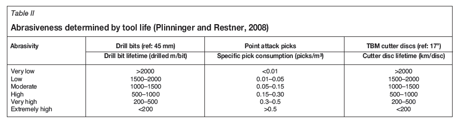