


Services on Demand
Article
 English (pdf)
 Article in xml format
 Article references
Indicators

Related links
-
 Cited by Google
 -
 Similars in Google
Share

 Permalink
Journal of the Southern African Institute of Mining and Metallurgy
On-line version ISSN 2411-9717
Print version ISSN 2225-6253
J. S. Afr. Inst. Min. Metall. vol.116 n.10 Johannesburg Oct. 2016
http://dx.doi.org/10.17159/2411-9717/2016/v116n10a10
GENERAL PAPERS
Premature failure of re-sulphurized steel studs
E. Molobi
Transnet Engineering, Product Development, Rotating Machines
SYNOPSIS
Studs are rods threaded on both ends and are used as mechanical fasteners for two or more components. Stud finds usage in industries such as automotive, construction and aviation. The advantage of studs is that they allow for disassembly of components during maintenance. Studs are continuously subjected to both tensile and shear stresses, depending on the application, therefore they should be manufactured from suitable materials that are capable of withstanding all these external forces. Studs are sometimes manufactured from re-sulphurized steel due to its improved machinability; however, there is a certain limit on the amount of sulphur, above which failure may occur. Premature failure of studs has been a common problem, but failed studs are commonly replaced with new ones without conducting failure investigations. The present work investigates the premature failure of two re-sulphurized steel studs used on a rocker arm assembly and recommends alternative materials. The investigation was carried out by conducting visual examination, microstructural analysis, hardness measurements, chemical analysis and a detailed scanning electron microscopy (SEM) investigation on the fracture surface.
Keywords: re-sulphurized steel, threaded fasteners, failure analysis, fatigue failure, manganese sulphide.
Introduction
Two rocker arm studs used on a 16-cylinder diesel locomotive engine failed prematurely after being in service for less than 5 months. The rocker arm studs had a life-cycle of 5 years. The studs were manufactured from re-sulphurized steel. The paper aims to establish whether re-sulphurized steel is applicable for the manufacture of studs in the automotive industry.
Background
Locomotives are classified as either electric or fuel-powered. Diesel locomotives are an example of fuel-powered locomotives. This type of locomotive uses a diesel engine as a means for propulsion. An engine converts chemical energy into mechanical energy required for traction. In an internal combustion engine a rocker arm is an oscillating lever that conveys radial movement from the cam lobe into linear movement to open and close poppet valves of cylinders (Husain and Sheikh, 2013). The rocker arms are secured on to the cylinder head by rocker arm studs.
During operation of the engine, stresses and vibrations are encountered leading to rocker arm stud deflection (Ridgeway, 1975). The deflection of rocker arm studs causes inefficiency in engine operation and gradually leads to metal fatigue and hence stud breakage or disengagement of the stud from the cylinder head due to loosening (Ridgeway, 1975). However, the latest designs incorporate a housing or adapter cover as a restraining means to prevent stud deflection (Ridgeway, 1975).
Incorrect torqueing of a rocker arm stud can lead to premature failure due to uneven stresses on the component (Roberts, 1997). Torqueing below the minimum requirements would lead to deflection and vibration of the stud, thus leading to fatigue damage and over-torqueing would lead to loss of compression and warpage of the stud (Roberts, 1997). However, the material of the stud also plays a vital role in sustaining the deflection, vibrations and stresses acting on the studs during operational service.
Re-sulphurized steel has found usage in the production of threaded components such as studs, bolts and screws, mainly to enhance machinability and in applications that require low tensile strength material.
Literature review
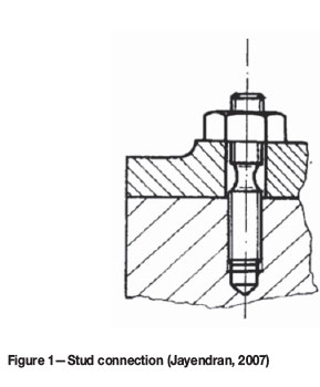
A stud is a relatively long rod that is threaded on both ends (Wikipedia, 2016), that is designed to be used in tension. Studs are used for joining parts to cast components. The tensile strength of cast iron is very low and excessive tightening of a set screw into a cast iron thread may cause the thread to crumble, thus permanently damaging the casting (Jayendran, 2007). Studs are first screwed into the casting and tightening is done using mild steel nuts. Any damage due to excessive tightening will be to the stud or nut and not the casting. Studs are used to ensure gas-tight and watertight joints in applications where heavy pressures are encountered (Jayendran, 2007). A typical stud connection is shown in Figure 1.
In many cases, threaded fastener joints are the weakest elements in a structure or mechanism (Toribo et al., 2010). This is because threads act as stress raisers and lead to easy crack initiation. The failure modes of threaded fasteners such as studs are: (i) overload, (ii) lack of locking mechanism, which cause the studs to become loose, (iii) fatigue failure, (iv) improper torque, (v) improper design, (vi) improper manufacture and (vii) corrosion failure (Roberts, 1997). Fatigue seems to be one of the most common problems and this can be due to insufficient pre-load, loosening, inadequate design considerations and material problems (Toribo et al., 2010).
Threaded fasteners are generally made from low- to medium-carbon steel, but other tough inexpensive metals may be substituted such as stainless steel, brass, nickel alloys, or aluminium alloy. The quality of the metal used is important in order to avoid cracking. Stud threads may be machined or rolled; in cases where machining is used the materials machinability becomes of utmost importance. Free-cutting steels are normally used in applications that require good machinability. Machinability of steels is dependent on hardness, chemistry, microstructure and the mechanical state of the metal (Stephenson and Agapiou, 2006).
Sulphur, phosphorus and lead are added to steel to enhance machinability. Sulphur does not alloy with the iron in steel but combines with the manganese to form sulphide inclusions (Bramfitt and Benscoter, 2002), as sulphur cannot form a solid solution with steel and thus remains as insoluble inclusions in the matrix. Manganese sulphide behaves as a solid lubricant, by coating and lubricating the rake face of the machining tool, hence reduces friction, tool chip temperature and tool wear (Bramfitt and Benscoter, 2002).
Although re-sulphurized steels are beneficial for machin-ability, the addition of sulphur adversely affects other mechanical properties such as corrosion resistance, ductility, toughness, formability and weldability (Stephenson and Agapiou, 2006).
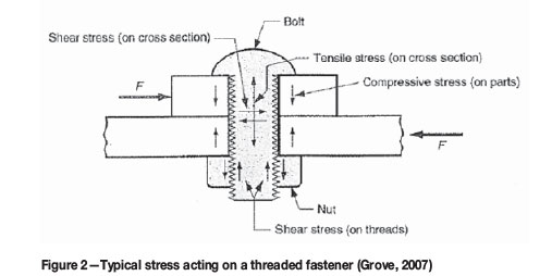
The stresses acting on threaded fasteners include both a tensile and a shear component (Grove, 2007). Once a threaded fastener is tightened, it is loaded in tension and the fastened parts in compression. In addition, the forces acting on the fastened parts may be acting in opposite directions, resulting in a shear stress on the threaded fastener cross-section. Figure 2 shows typical forces acting on a threaded fastener.
Experimental method
The fracture surfaces of studs A and B were examined visually. The condition of the stud threads was also examined. Magnetic particle inspection was carried out by use of a magnetic yoke and magnetic particles on a white background for crack detection. Chemical analysis was carried out by mass spectrometry. Hardness measurements were conducted using a Brinell hardness meter under a load of 3000 kg and with a 10 mm ball indenter. Metallographic samples were sectioned from studs A and B and mounted in a resin for easy handling. Following mounting, the sectioned samples were ground and polished and etched with 2% nital for microstructural analysis. The fractography of studs A and B was analysed by scanning electron microscopy (SEM) using energy dispersive X-ray (EDX) spectrometry to quantify and identify the inclusions present.
Results and discussion
Visual examination
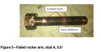
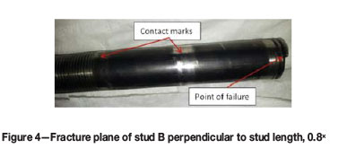
Visual examination entailed examination of the stud threads and fracture surface. Contact marks were observed on both studs A and B (Figures 3 and 4); these contact marks could have been formed either before or after stud fracture and could be due to loosening or under-torqueing of the studs. Necking in the longitudinal axis of the studs was not evident and no thread wear or thread mechanical damage was visible. Lack of necking shows that stud over-torqueing was unlikely to be the cause of failure.
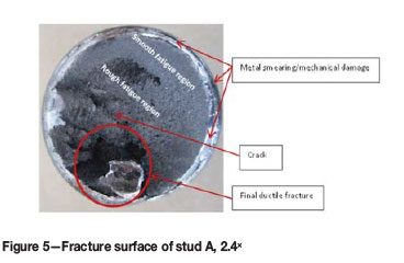
The fracture surface of stud A (Figure 5) was perpendicular to the stud axis. Mechanical damage and metal smearing was observed close to the stud peripheral, hence the failure origin could not be established. The roughness of the fracture surface was not uniform and the overload region displayed material tearing. The change in roughness of the fracture surface is one of the indications of fatigue failure. Progression marks were not observed on the fracture surface and final fracture occurred in approximately the 5 o'clock to 7 o'clock position. Lack of progression marks indicates that the load did not vary during the life of the crack. Cracking and material tearing was also observed. The final fracture displayed a ductile mode of failure.
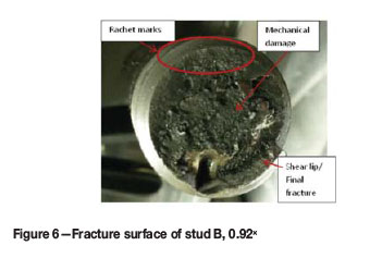
The fracture surface of stud B (Figure 6) was perpendicular to the stud axis. Ratchet marks were observed in the 10 o'clock to 1 o'clock position (Figure 6 and 7); these are indicative of fatigue failure. Progression marks were not evident. A shear lip was evident in the 4 o'clock to 7 o'clock position, which is the point of final fracture and cracks were also observed on the fracture surface. The presence of a shear lip may indicate a ductile failure mode. Mechanical damage was also present in areas of the fracture surface, hence the difference in surface roughness of the fracture surface could not be observed.
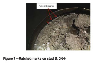
The threads of both stud A and B showed no evidence of mechanical damage except for the thread in which failure occurred. No progression marks were observed on either stud; hence it is unlikely that the failure was due to stud under-torqueing. The stress level during crack growth did not vary, which is unexpected of a loose stud. The presence of ratchet marks on stud B is evidence of multiple crack origins; however, the final fracture was less than 50% of the surface area of the fracture, hence it is evident that the stress at the time of failure was low. Ratchet marks indicate the presence of stress raisers.
Magnetic particle inspection (MPI)
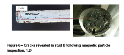
Magnetic particle inspection revealed cracks on stud B (Figure 8). The crack observed on the fracture surface of stud B (Figure 6) was continuous in the longitudinal direction of the stud.
Chemical analysis and hardness properties
Samples were sectioned from studs A and B for spectrometric analysis. Mass spectrometry was used to analyse the chemical composition of the studs. The analysis is shown in Table I. The elemental analysis complied with the requirements of a re-sulphurized steel according to specification SAE 1144. Re-sulphurized steels contain significant quantities of sulphide stringers, which reduce their resistance to fatigue (Bramfitt and Benscoter, 2002) and are not acceptable for use in high-stress and high-cycle vibration fatigue applications, such as studs (Grove, 2007).
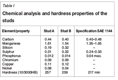
The Brinell hardness of stud A and stud B was measured to be 257 and 259, respectively.
Re-sulphurized steels contain particulate phases that reduce their resistance to fatigue (ASTM E45, 2013) and are not acceptable for use in high-stress and high-cycle vibration fatigue life, such as stud fasteners (Smith, 1994). These steels can safely be used in low-ductility applications.
Metallographic examination
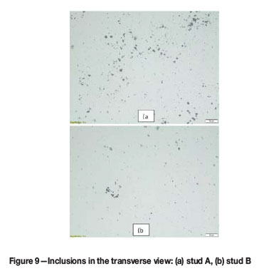
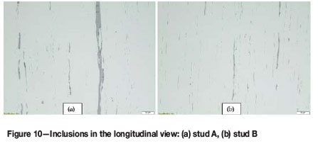
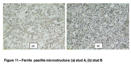
The microstructural analysis showed both studs to be composed of pearlite in a ferritic matrix. Level 5 sulphide inclusions were present throughout the ferritic matrix in accordance with specification ASTM E45 (2013). The presence of sulphide stringers indicates that the studs were hot-rolled. Figures 9 to 11 show optical micrographs of studs A and B.
Scanning electron microscopy
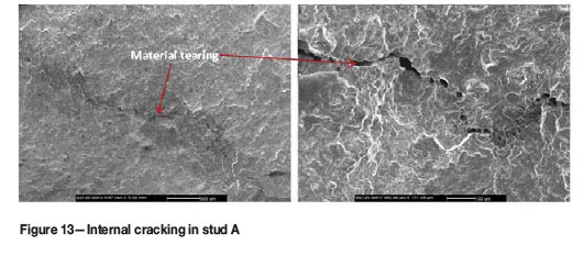
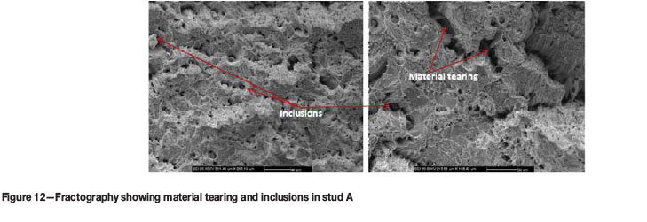
The fracture surface of stud A was cleaned using acetone and dried before examination under SEM. The fractography displayed material tearing with numerous cracks, which is characteristic of a ductile dimple fracture mode (Figure 12).
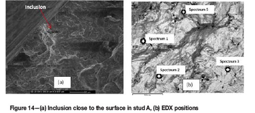
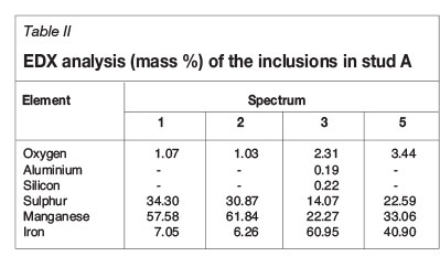
The cracks and tearing originated from inclusions, which were also present close to the stud surface (Figure 13 and Figure 14a). EDX analysis was conducted to identify and quantify the elemental composition of the inclusions; the EDX positions are shown in Figure 14b. The analysis revealed the inclusions to be MnS (manganese sulphide); results are shown in Table II.
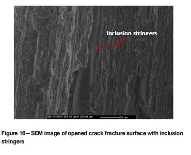
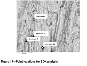
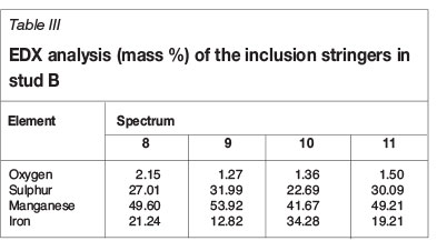
The crack observed on the fracture surface of stud B (Figure 6) was opened (Figure 15) and the crack fracture surface was analysed using SEM. Elongated inclusion stringers were present in the longitudinal direction of the stud (Figure 16) and the fracture surface had a 'woody' appearance, as shown in Figure 15. EDX analysis was conducted on the inclusion stringers to determine and quantify the chemical composition; the EDX positions are shown in Figure 17. EDX revealed the stringers of inclusions to be MnS (Table III). The MnS stringers were elongated in the stud rolling direction; which indicates that the studs were hot-rolled and confirms the pearlitic structure in the ferrite matrix. Sulphur is deformable at high temperatures and becomes elongated during forming processes such as rolling (Cyril, Fatemi and Cryderman, 2008).
Stringers of MnS inclusions are known to have adverse effects on the mechanical properties of a component, provided that the inclusions are not aligned with the loading direction (Cyril, Fatemi and Cryderman, 2008). Shear stress perpendicular to the stud axis is present due to the components being joined. It is thus expected that the fatigue properties in the transverse direction of the stud will deteriorate as compared to those in the longitudinal direction. It is probable that the studs failed from fatigue loading caused by the transverse shear stresses, with MnS inclusions as the initiation points, which reduced the fatigue strength of the studs.
Conclusions and recommendations
► The presence of MnS (manganese sulphide) inclusions reduces resistance to fatigue in the transverse direction
► The lack of necking proved that over-torqueing could not have been the cause of failure
► The lack of progression marks and mechanical damage on the rest of the threads suggests that under-torqueing is unlikely to be the cause of failure
► The most probable cause of failure is the presence of large MnS inclusions, which acted as initiation points for fatigue failure. Both transverse shear forces and longitudinal tensile forces could have led to failure
► Re-sulphurized steels are used for applications such as screws, which are subjected to low loads, but are not suitable for high-load application components such as these studs
► It is recommended that studs be manufactured from materials with good strength, hardness and impact properties regardless of anisotropy. These include chromium-nickel steels, which have increased toughness and strength.
References
ASTM E45. 2013. Standard Test Methods for Determining the Inclusion Content of Steel. Vol. 03.01. Materials Park, OH. pp. 1-19. [ Links ]
Bramfitt, B.L. and Benscoter, A.O. 2002. Metallographer's Guide: Practice and Procedures for Irons and Steel. 4th edn. ASM International, Materials Park, OH. [ Links ]
Cyril, N., Fatemi, A. and Cryderman, B. 2008. Effects of sulfur level and anisotropy of sulfide inclusions on tensile, impact and fatigue properties of SAE 4140 steel. SAE International Journal of Materials and Manufacturing, vol. 1, no. 1. pp. 218-227. [ Links ]
Groove, M.P. 2007. Fundamentals of Modern Manufacturing. 3rd edn. Wiley. [ Links ]
Husain, S.M. and Sheikh, S. 2013. Rocker arm: a review. International Journal of Innovative Research in Science, vol. 2, no. 4. pp. 1120-1126. [ Links ]
Jayendran, A. 2007. Joining of Metals by Mechanical Methods. 1st edn. Springer. [ Links ]
Ridgeway, R.H. 1975. Rocker arm stud support device. US patent 3870024. [ Links ]
Roberts, C. 1997. The consequences of bolt failures. http://www.crobers.com/bolt.htm [accessed 23 May 2016]. [ Links ]
Schmidt, F.E., Hineman, M.A. and Schmidt, B.F. 2014. Improper materials selection in motorcycle stud bolt. Microscopy and Microanalysis, vol. 20, no. S3. pp. 1856-1857. [ Links ]
Smith, E.H. 1994. Mechanical Engineer's Reference Book. 12th edn. Butterworth-Heinemann. [ Links ]
Stephenson, D.A. and Agapiou, J.S. 2006. Metal Cutting Theory and Practice. 2nd Eedn. Taylor and Francis. [ Links ]
Toribo, J., Gonzalez, B., Matos, J.C. and Ayaso, F.J. 2010. Analysis of Failure Paths in Steel Bolted Connections. University of Salamanca. pp. 521-528. [ Links ]
Wikipedia. 2016. Studs. https:en.wikipedia.org/wiki/threaded_rod [accessed 23 May 2016]. [ Links ]
This paper was first presented at the AMI Ferrous and Base Metals Development Network Conference 2016 19-21 October 2016, Southern Sun Elangeni Maharani, KwaZulu-Natal, South Africa.

