


Serviços Personalizados
Artigo
 Inglês (pdf)
 Artigo em XML
 Referências do artigo
Indicadores

Links relacionados
-
 Citado por Google
 -
 Similares em Google
Compartilhar

 Permalink
Journal of the Southern African Institute of Mining and Metallurgy
versão On-line ISSN 2411-9717
versão impressa ISSN 2225-6253
J. S. Afr. Inst. Min. Metall. vol.116 no.10 Johannesburg Out. 2016
http://dx.doi.org/10.17159/2411-9717/2016/v116n10a9
GENERAL PAPERS
Effect of yield strength on wear rates of railway wheels
V.J. MatjekeI, II; J.W. van der MerweII, III; M.J. PhashaI; A.S. BolokangI; C. MoopanarI
ITransnet Engineering, Research & Development, Kilner Park, Pretoria, South Africa
IISchool of Chemical and Metallurgical Engineering, University of the Witwatersrand, Johannesburg, South Africa
IIIDST-NRF Centre of Excellence in Strong Materials, School of Chemical and Metallurgical Engineering, University of the Witwatersrand, Johannesburg, South Africa
SYNOPSIS
Excessive wear rates on railway wheels can result in rolling-stock derailments. If wear is detected early the possible derailments can be prevented by prematurely replacing wheelsets, although the inventory cost and maintenance downtime remain a challenge. In the current study, wheels were introduced and monitored in-service for two years to investigate the cause of excessive wear rates. The wear rates and stresses were calculated for the wheels suitable for a maximum load of 26 t per axle. Microstructural and mechanical properties were analysed. As expected, the general microstructure of all the wheels tested was pearlitic. Although all the wheels complied with the tensile strength requirements, stress calculations confirmed material distortion on excessively worn wheels whereas trial wheels revealed yield strength exceeding the yield criterion. High wear rates observed on the wheels were a result of low yield strength relative to the load per axle. The typical wear mechanism found was due to a combination of rolling contact fatigue and abrasive brake wear. Despite compliance of the wheels with existing requirements regarding material and mechanical properties (hardness, ultimate tensile strength), it is recommended that the yield strength must also be taken into consideration as a critical parameter.
Keywords: railway wheels, wear rate, yield strength, wear mechanism, rolling contact fatigue.
Introduction
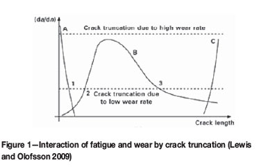
Railway wheels are used to support the wagon mass and guide the wagon along the tracks (Park, 1974). The wheels and rails must be able to tolerate the applied tangential forces in order to effect wagon dynamic performance and reduce material deformation (Ghidini et al., 1994; RSE_TE_SPC_0045, 2011; AAR M107/M 208 Specification, 2011. Over the past ten years, the South African coal wagon maintenance depot has experienced excessive hollow wheel wear rates on the heavy haul line wheels. The maximum load of Jumbo wagons on the coal line is 104 t, or 26 t per axle. Although the maintenance intervention cycle for wheelsets was two years, between February 2011 and August 2012 some wheels experienced excessive hollow wear. Hollow wear is regarded as wear exceeding 2 mm on the central portion of the wheel tread (RSE_TE_SPC_0045, 2011). This happened despite the fact that these wheels were manufactured and certified according to the requirements of AAR M107/208 standard for carbon steel wheels (AAR M107/M 208 Specification,. 2011) and the local wheel RS/ME/SP 021 standard specification (RS / ME / SP / 021 REV 5 (2013). The AAR standard only specifies a minimum hardness as a required mechanical property and the local standard specifies hardness and minimum tensile strength only. In general, an increase in hardness will improve the rolling/sliding wear resistance of steel. This relationship of hardness and wear resistance was found to be true only in a situation where solid and similar alloys are in contact (Singh, Khatirkar and Sapate, 2015). The sliding wear resistance of a material is usually estimated using Archard's equation (Liu and Li, 2001). This wear mechanism may manifest by crack initiation at the surface and propagation until macroscopic wheel material detachment occurs (Johnson, 1989). Fatigue crack initiation occurs as a result of local plastic deformation (Johnson, 1989; Ekberg, 2001). This plastic deformation and fatigue crack-related detachment forms hollow wear within the wheel/rail interface and progresses over many rolling contact cycles. Lewis and Olofsson (2009) stated that 'severe wear results in a rough, deep torn surface - much rougher than the original metallic wear debris, typical of up to 10 μm'. It was further indicated that there is a relationship between crack truncation and wear rate; if the wear rate is high, cracks will probably be worn away before progressing beyond stage A in Figure 1, otherwise the crack becomes unsafe when it reaches point C.
Heat treatment is the most important process for improving wheel rim hardness and subsequently wear resistance (Ekberg, 2001). Residual compressive stresses are introduced in the wheel rim by a rim quenching process during heat treatment that refines the grain structure and as a result improves the wear resistance as well as the resistance to crack initiation (Johnson, 1989). Excessive hollow wear can affect the dynamic behaviour of the railway vehicle and will lead to the increased likelihood of derailments (Lewis et al., 2003). Although the main focus of this paper is on excessive wear rates, wheel-rail interaction is also important. When the contact area between the wheel and rail is small, there is a corresponding high contact stress. Typical contact is made over a quasi-elliptical area with an average diameter of approximately 13 mm (Harris et al., 2001).
This research study was initiated to deepen the understanding of the wear mechanism experienced on the coal line. This will aid efforts to identify and abate the wear rates, as well as in determining combative measures to reduce the wear of the wheels. In order to investigate this, an enhanced understanding of the current operating conditions, wheel mechanical properties, metallographic properties, wear mechanisms and wear regimes is essential.
Background and experimental procedure
Excessively worn wheels
Initially, two batches of wheels that showed high wear rates in-service were declared unroadworthy and were removed from service. Three wheelsets from the two batches were selected for further analysis. The chemistry and tensile properties of these batches were provided by the supplier. Both batches were manufactured by Supplier A (wheel A). The degree of wear was measured using the miniprof wheel rim measurement technique. In addition, microstructural analysis around the excessively worn area on the wheel tread was conducted using optical and scanning electron microscopy (SEM). The hardness results related to the excessively worn wheel test batch were not available. In addition, no further comparative hardness testing could be carried out on the worn wheels due to their condition and profile. However, according to Zang, Li and Zhang, (2011) and Dieter (1988) the hardness of materials often obeys the three times empirical strength relationship of work-hardening metals, therefore an extrapolation of material hardness was carried out using the material yield strength.
Ring-fenced wheels
In an effort to further understand the wear mechanism, thirty-two brand-new wheelsets were ring-fenced for trials and monitored for a period of two years on the coal Jumbo wagons. These new wheelsets were supplied by two different companies. The wheels were profiled to the nominal diameter and put in service for wear monitoring. The operating conditions were similar to the conditions that existed in 2011. Sixteen of the 32 wheelsets were manufactured by 'Supplier A' (wheel A) and the other 16 were manufactured by 'Supplier B' (wheel B). Each bogie of the wagon was paired with wheelsets made up of a combination of both wheels A and B. Unfortunately, four wagons were removed due to operational demand and therefore could not complete the trial; and as a result they were excluded from the study. The remaining 16 wheelsets that completed the trial were measured bi-annually.
In additional, a wheel from each supplier was tested to determine the chemistry, microstructural analysis and mechanical properties.
Loading conditions analysis
The wear rate of the tread surface depends on loading conditions, therefore the loading conditions were analysed according to compliance criteria from UIC Code 510-5 (2007) and EN 13103 standards. The applied forces were calculated and the main goal of the two-body contact interface analysis was to determine the magnitude of stresses and deformations.
Results
Excessively worn wheels
The three wheelsets that were removed from service were identified as 8JS6699/024, 8US6855/003 and 8SU6085/046. Wheelset 8JS6699/024 was in service for 9 months while 8US6855/003 and 8SU6085/046 were in service for 18 months.
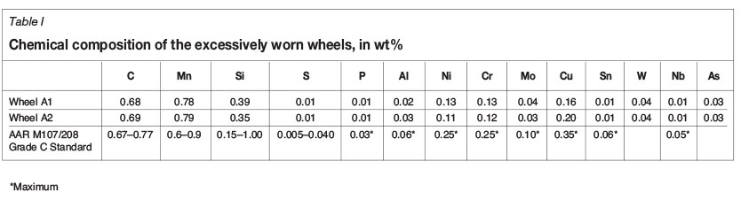
Chemical composition
The chemical composition of the excessively (abnormal) worn wheels from supplier A is shown in Table I. The chemical composition and mechanical properties were found to be in accordance with the requirements of AAR M107/M 208 and RS/ME/SP 021 specifications, respectively.
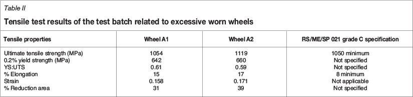
Tensile test
The tensile tests results of the quality test batch related to the excessively worn wheels are shown in Table II. These results were found to be satisfactory and compliant with the local specification. The material hardnesses that were extrapolated were found to be approximately 310 HV and 329 HV, (290 HB and 309 HB when converted to Brinell hardness) respectively (Dieter, 1988).
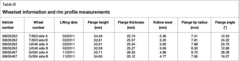
Miniprof wheel measurement of the rim profiles
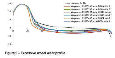
The rim profile was measured and evaluated according to the requirements of RSE/TE/SPC/0045 (2013). The total average wear rate was found to be 0.33 mm/month according to the rim profile measurements in Table III. The wear rates were found to be excessive considering that the wheels were in service for a period of 9-18 months.
Figure 2 shows the excessive hollow wear on the wheel rim profiles.
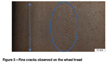
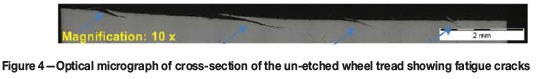
Wheel tread analysis
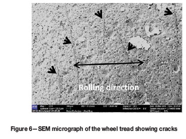
The treads of the wheels that experienced excessive wear were examined with a stereoscope and optical microscope. The treads revealed fine microscopic cracks, as shown in Figure 3 and Figure 4. The cracking mechanism is similar to that discussed by Lewis and Olofsson (2009); where the wheel surface experiences deformations as a result of cyclic loading, leading to crack initiation which ultimately results in the loss of particles from the surface. Lewis et al. (2003) described this phenomenon as 'ratcheting'.
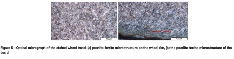
The general microstructure of the wheel was pearlitic with ferrite embedded on the grain boundaries. The microstructure observed during metallographic examination showed wheel tread plastic deformation of approximately 75 μm (see Figure 5). The wheel tread surface shows a breakage classified as severe wear.
Figure 6 shows a SEM micrograph detailing the fatigue micro-cracks on the excessively worn wheel.
Analysis of ring-fenced wheels
The metallurgical and mechanical testing results of the two wheels sampled from supplier A and B are presented below.
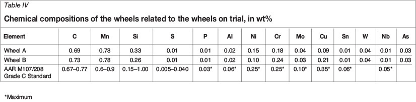
Chemical composition
Chemical compositions of the trial wheels examined are given in Table IV. The chemical compositions of both wheels conformed to the AAR M107/208 specification. The carbon content of wheel A was 5.5% lower than that of wheel B; this difference is significant given the importance of carbon as an element that influences hardenability.
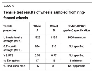
Tensile strength
The tensile test results are shown in Table V. Results of both wheels complied with the requirements of RS/ME/SP021. The ultimate tensile strength and yield strength of the trial wheels were significantly better than the values for the wheels that experienced excessive wear.
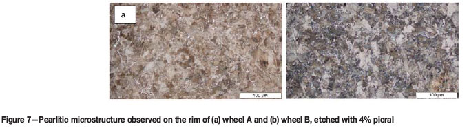
Metallography
Transverse sections of the two wheels sampled from the ring-fenced wheels were prepared for metallographic examination. The general microstructure of the two wheels was pearlitic with ferrite embedded on the grain boundaries (Figure 7).
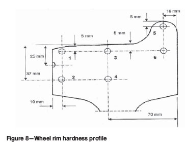
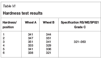
Hardness testing
A microslice from the rim on the wheels identified for destructive testing was sectioned and prepared for Brinell hardness testing. The wheel rim hardness tests were conducted at the positions indicated in Figure 8 and the results are presented in Table VI. All wheels complied with the minimum and maximum hardness requirements of specification RS/ME/SP021 grade C alloy. The hardness measurements were comparable and did not show the effect of the 5.5% carbon variation.
Ring-fenced wheels
Only 16 of the 32 ring-fenced wheelsets were analysed, as mentioned, and the results are discussed below. All the wheels used in the test were manufactured through a forging proces.
Miniprof measurements
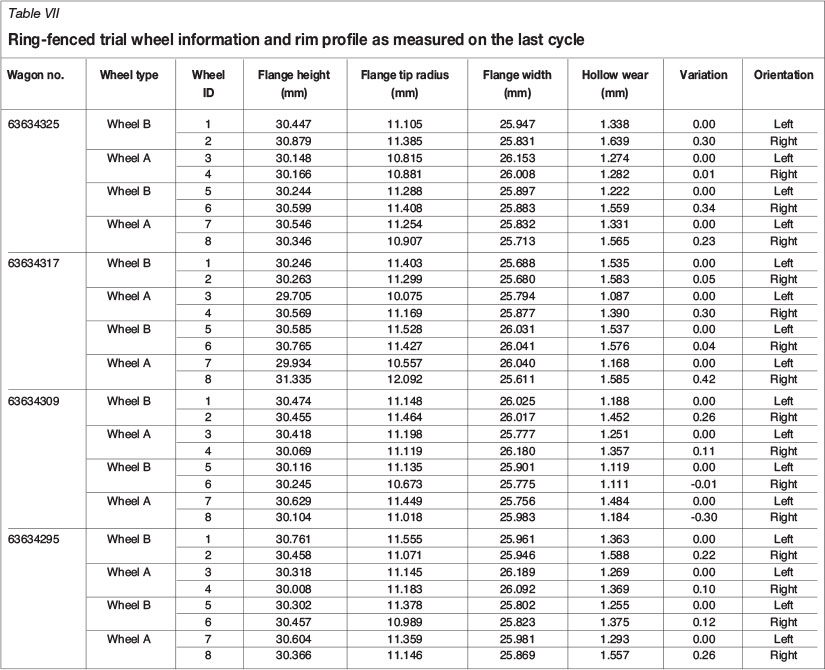
The results listed in Table VII are the rim profile measurements for the last cycle measurements over a 24-month period.
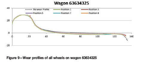
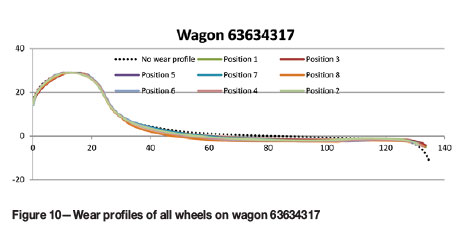
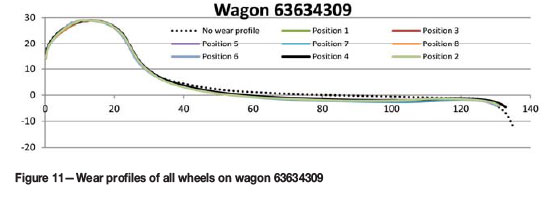
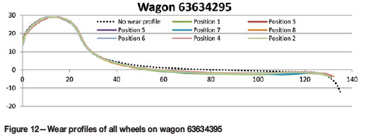
Of the 16 wheelsets shown in Table VII, 14 of the left-hand side wheels on the wagons were worn more than those on the right-hand side. Only two of the right-hand wheels showed pronounced wear. The hollow wear on trial wheels was satisfactory considering that the average wear rate was 0.06 mm/month and the maximum variation was 0.42 mm per wheelset. Figures 9-12 show the wheel rim profiles per wagon. Thee wear rates of the trial wheels are significantly lower than the wear rates in Table III.
The asymmetrical hollow wear that was observed on the excessively worn wheels, as originally detected in 2011 and 2012, was indicative of a batch with inferior mechanical properties. The asymmetrical wear on the trial wheels was not as pronounced and as such was deemed normal and acceptable. The high wear rates of the excessively worn wheels also indicate that there is a possibility that the wheel material was of inferior mechanical properties with reference to the trial (ring-fenced) wheels. In general, excessive wear was predominant on wheels identified as wheel type A in 2011 and 2012.
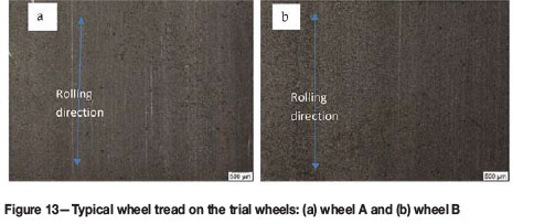
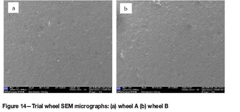
Wheel tread analysis
The tread of the trial wheel shown in Figure 13 was smooth, without signs of the cracks observed on the excessively worn wheels seen in Figure 3. Furthermore, microscopic examination of the wheel tread did not reveal any operation-related defects, except for random micro-spalling seen in Figure 13 and 14. The wear mode was characterized as mild wear. The wheel with high wear rates in Figure 6 showed larger spall marks than the trial wheels in Figure 14 at the same magnification.
Loading conditions and compliance criteria from UIC Code 510-5
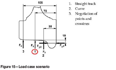
This section focuses on wheel load and compliance criteria from UIC Code 510-5 (2007) and BS EN 13103 (2009) standards. The applied forces were calculated on the basis of the value of load Qg. Load Qg is defined in the EN 13103 standard as half the vertical force per wheelset on the rail (BS EN 13103, 2009). The main goal of the two-body contact interface analysis was to calculate the magnitude of stresses and deformations. UIC Code 510-5 recommends that for design purposes, three load cases must be considered, namely Load case 1: straight track, Load case 2: curve and Load case 3: negotiation of points and crossings. However, for the purpose of investigating hollow wear only Load case 1 is applicable.
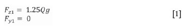
Load case 1
This load case is for a centred wheelset on a straight track as represented by 1 (highlighted) in Figure 15. Equation [1] was used to calculate the loads tabulated in Table VIII.
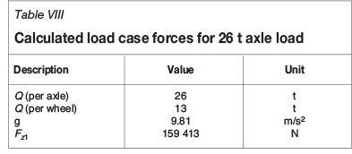
Hertzian contact stress theory
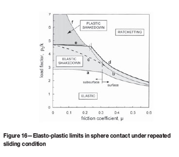
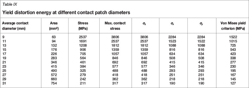
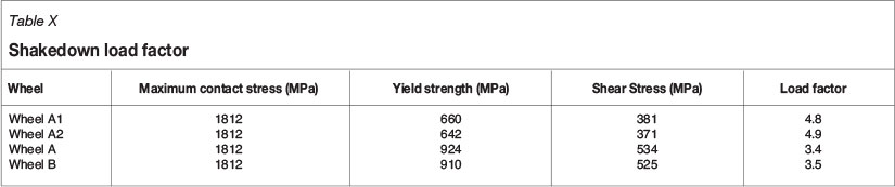
Hertz (Johnson, 1985) developed a theory to calculate the contact area and pressure between two surfaces and predicted the resulting compression and stress induced on the objects. The principal stresses acting along the x, y, z axes at or below the contact area are σχ, oyand σζ. The shear stresses acting along the axes at or below the contact area are zero. The current manufacturing specification does not specify the minimum yield strength; however, according to the distortion energy theory; the yield strength is an important property. Harris et al. (2001) found that the wheel/rail interaction contact is made over a quasi-elliptical contact patch the size of a small coin of about 13 mm (½ inch) diameter. A minimum diameter of 13 mm was used to calculate the yielding criterion strength for a 26 t per axle load wagon (see Table IX). The results for the excessively worn wheels presented in Table IX show that the yielding criterion exceeded the uniaxial yield strength of wheel A at a contact patch of 13 mm diameter. The elasto-plastic response shown in Figure 16 was extensively analysed by Johnson (1989). The load factor of the excessively worn wheels and the ring-fenced wheels at a maximum contact stress of 1812 MPa are summarized in Table X. Given the interpretation of elasto-plastic behaviour of the wheels at approximately 0.3 coefficient of friction, it is expected that excessively worn wheel A will distort and be more susceptible to both surface fatigue and development of hollow wear in service than the ring-fenced wheels A and B, which showed high yield strength values compared to the values determined by the Von Mises and Tresca criteria.
Discussion
Shear flow on the excessively worn wheels and fatigue microcracks suggest a great amount of shear deformation of material on the tread surface. Olofsson et al. (2013) found that cyclic loading that leads to wheel surface deformation results in crack nucleation and subsequently removal of material. The excessively worn wheels revealed plastic deformation on the tread that resulted in the initiation of cracks. The wear on the wheels most likely occurred by a form of material detachment at the intersection of cracks. The wear observed in this research occurred by rolling contact fatigue that progressed by the shedding of small particles. The ring-fenced wheels did not exhibit any unusual wear-related defects and since the only difference between the wheels is strength, it is therefore concluded that the wear mechanism is related to the material strength. The tension/shear forces are complicit in the formation of fatigue cracks and material shear deformation.
The test certificate of the wheels showing initial excessive wear revealed a significantly lower yield strength compared to the ring-fenced wheels, although only the ring-fenced wheels satisfied the minimum AAR and local specifications. However, it is worth noting that the yield strength is not a requirement for both specifications. Hardness testing of the excessively worn wheels could not be carried out due to deformations and high wear rates; however, Dieter (1988) reported that empirically the yield strength is three time the hardness of work-hardening materials, therefore the hardnesses of the wheels were extrapolated using the empirical relationship. The converted hardness results did not conform to the minimum requirement of AAR M107/208 and local specification requirements. On the other hand, the Archard wear equation shows that the material surface hardness is inversely proportional to wear resistance and therefore, the likelihood of wear increases with lower hardness (Liu and Li, 2001; Barwell, 1974).
Based on Hertz's theory, the calculated contact area and pressure between wheel and rail predicts plastic deformation on the wheels that ultimately resulted in excessive wheel wear (Barwell, 1974). Stress calculations suggest that the excessively worn wheelsets were exposed to heavy loading, i.e. high normal and tangential forces. The ring-fenced wheels' yield strength exceeded the calculated Von Mises and Tresca stresses. The high stress in this instance was determined using a contact patch with an average 13 mm (long diagonal) elliptical diameter.
The ring-fenced wheels showed endurance performance by exhibiting lower wear rates compared to the excessively worn wheels. The lasting performance in the ring-fenced wheels is largely related to the higher yield strength in comparison to the excessively worn wheels.
Conclusion
The high wear rates observed on the excessively worn wheels from supplier A were as a result of low yield strength relative to the load per axle. The typical wear mechanism found here is a combination of rolling contact fatigue and abrasive brake wear. It is recommended that local and AAR specifications should consider minimum yield strength to determine axle load. Furthermore, the development of an optimized heat treatment process aimed at increasing the hardness and yield strength of AAR class C wheel rims will result in a considerable increased wheel life.
Acknowledgements
The wheel profiles used in this report were measured by Georg Hettasch and Victor Ngobeni, who are gratefully acknowledged by the authors.
References
AAR M107/M 208 specification. 2011. Wheels, carbon steel. Association of American Railroads. pp. 1-40. [ Links ]
Barwell, F. 1974. The tribology of wheel on rail. Tribology International, vol. 7. pp. 146-50. [ Links ]
BS EN 13103. 2009. Railway applications - Wheelsets and bogies - Non-powered axles - Design method. [ Links ]
DIETER, G.E. 1988. Mechanical Metallurgy. McGraw-Hill. 243-6, 331. [ Links ]
Ekberg, A. 2001. Anisotropy and rolling contact fatigue of railway wheels. International Journal of Fatigue, vol. 23. pp. 29-43. [ Links ]
Ghidini, A., Belotti, G., Patrioli, L. et al. 2004. Starting of an innovative line for heat treatment of railways solid wheels and tyres. Proceedings of the International Wheelset Congress, University of Illinois, Chicago. [ Links ]
Harris, W.J., Tournay, H., Ebersöhn, W. and Zakharov, S.D.L.J. 2001. Guidelines to best practices for heavy haul railway operations: management of the wheel and rail interface issues. International Heavy Haul Association, Virginia Beach, VA. 484 pp. [ Links ]
Johnson, K.L. 1989. The strength of surfaces in rolling contact. Mechamical Engeering Science, vol. 203, no. 33. pp. 151-163. [ Links ]
Johnson, K.L. 1985. Contact Mechanics. Cambridge University Press, Cambridge, UK. [ Links ]
Lewis, R. and Olofsson, U. 2009. Wheel-Rail Interface Handbook. CRC Press, UK. [ Links ]
Lewis, R. Braghin, F., Ward, A., Bruni, S., Dwyer-Joyce, R.S., Bel Knani, K. and Bologna, P. 2003. Integrating dynamics and wear modelling to predict railway wheel profile evolution. Proceedings of the 6th International Conference on Contact Mechanics and Wear of'Rail/Wheel Systems (CM2003), Gothenburg, Sweden, 10-13 June. pp. 7-16. [ Links ]
Liu, R. and Li, D.Y. 2001. Modification of Archard's equation by taking account of elastic / pseudoelastic properties of materials. Wear, vol. 251. pp. 956-64. [ Links ]
Olofsson, U., Zhu, Y., Abbasi, S., Lewis, R. and Lewis, S. 2013. Tribology of the wheel-rail contact - aspects of wear, particle emission and adhesion. Vehicle System Dynamics, vol. 51, no. 7. pp. 1091-1120. [ Links ]
PARK, S. 1974. The tribology of wheel on rail. Tribology International, vol. 2. pp. 146-50. [ Links ]
RSE_TE_SPC_0045. 2011. Geometric requirements for new, reprofiled and in service wheelsets. [ Links ]
RS / ME / SP / 021 REV 5. 2013. Transnet freight rail specification for the supply of wrought wheels for tractive and trailing stock. [ Links ]
Singh, K., Khatirkar, R.K. and Sapate, S.G. 2015. Microstructure evolution and abrasive wear behavior of D2 steel. Wear, vol. 328. pp. 206-216. [ Links ]
UiC 510-5. 2007. Technical approval of monoblock wheels. [ Links ]
Zhang, P., LI, S.X. and Zhang, Z.F. 2011. General relationship between strength and hardness. Material Science and Engineering A, vol. 529. pp. 62-73. [ Links ]
This paper was first presented at the AMI Ferrous and Base Metals Development Network Conference 2016 19-21 October 2016, Southern Sun Elangeni Maharani, KwaZulu-Natal, South Africa.

