


Serviços Personalizados
Artigo
 Inglês (pdf)
 Artigo em XML
 Referências do artigo
Indicadores

Links relacionados
-
 Citado por Google
 -
 Similares em Google
Compartilhar

 Permalink
Journal of the Southern African Institute of Mining and Metallurgy
versão On-line ISSN 2411-9717
versão impressa ISSN 2225-6253
J. S. Afr. Inst. Min. Metall. vol.116 no.10 Johannesburg Out. 2016
http://dx.doi.org/10.17159/2411-9717/2016/v116n10a5
GENERAL PAPERS
Corrosion characteristics of mild steel storage tanks in fluorine-containing acid
R. van der MerweI, II; L.A. CornishI; J.W. van der MerweI
ISchool of Chemical and Metallurgical Engineering, University of Witwatersrand, Johannesburg and DST- NRF Centre of Excellence in Strong Materials, hosted by the University of the Witwatersrand
IIApplied Chemistry Department, South African Nuclear Energy Corporation SOC Limited (Necsa)
SYNOPSIS
The hydrofluoric acid (HF) industry in South Africa uses normalized mild steel (SA 516 Gr 70) for the storage and distribution of its technical-grade product (70% HF). The technical-grade acid is split from the anhydrous hydrogen fluoride (AHF) product during distillation just after HF is produced, in a stainless-steel-lined kiln, from the reaction of calcium fluoride (CaF2) with sulphuric acid (H2SO4). Uniform corrosion of the storage tanks is mitigated during commissioning by contacting the steel with 70% HF. A corrosive reaction takes place (2H+ + 2F- + Fe → H2 + FeF2) to form scale inside the tank which diminishes the attack of the steel by fresh HF, thus prolonging the service life expectancy of the vessels. This iron fluoride scale in the vessel grows continually, resulting in corrosion of the vessels continuing at a predictable rate (approx. 0.5 mm/a) since the first commissioning of the tanks at Necsa in 1993.
In early 2012, an increase in the average corrosion rate of the tanks to 3 mm/a measured at and below the liquid band in the storage vessels was noted. Three months later the corrosion rate had increased to 30 mm/a, just before the first leak from the tank was detected. The tanks were decommissioned shortly afterwards and an investigation revealed that the rapid corrosion was due to the presence of increased levels (>50 ppm) of nitric acid (HNO3) in the tanks, which attacked the fluoride layer protecting the steel.
The oxidation characteristics of high concentrations of HNO3 with low concentrations of HF on stainless steel surface treatment are well documented. The effects of low levels of nitric acid on the corrosion of steels in sulphuric acid are also known, but no suitable published data currently exists on corrosion by high HF concentrations with low HNO3 concentrations. Establishing the rate and mechanism of corrosion by HNO3 (0.1 to 1%) in 70% HF is currently a high priority for the HF industry in South Africa and will become increasingly important in the near future due to depleting fluorite reserves and cheaper, but less efficient, processes producing H2SO4 with higher impurity levels, which were not anticipated in the original plant design. The aim of this study is to simulate the corrosion conditions in the plant on a laboratory scale in order to establish the corrosion characteristics of the steels used in the HF plant, which are increasingly exposed to the HNO3 impurities that tend to concentrate in the final technical-grade HF acid product.
Keywords: hydrofluoric acid, mild steel, corrosion, nitric acid contamination.
Introduction
Mild steel is a relatively inexpensive material that is often effectively used for the storage and distribution of technical-grade hydrofluoric acid (70% HF). Uniform corrosion of HF storage tanks is inevitable and typically reaches 0.5 mm/a (Valkenburg, 2012). The thickness of the steel is regularly monitored ultrasonically and documented during inspections so that the service life can be safely anticipated. However, despite the regular inspections and current contingencies in the HF plant at Necsa, an isolated case of HF leakage from two mild steel vessels during operation occurred without warning (Valkenburg, 2012). The failure of both these vessels necessitated their premature decommissioning and uncovered a real need to understand the corrosion characteristics of mild steel used in the HF industry and recommend corrosion design improvements.
The reason for the failure of the mild steel was traced to an excess of nitric acid (HNO3) in the feedstock to the plant, which eventually concentrated in the technical-grade HF product downstream. The combined corrosion effect of HF and HNO3 in the storage tanks led to their premature failure.
A study to simulate the corrosion conditions in the laboratory was required to better estimate the service life of the steels used in the HF plant. Understanding the effect of HNO3 contamination on the plant's steels and the determination of corrosion inhibition strategies was essential. Laboratory immersion experiments were required to establish the corrosion characteristics of the mild steel used in a HF plant, which could be exposed to >50 ppm HNO3 impurities. Neither published, nor quantitative, corrosion data on the corrosiveness of HF in the presence of an oxidizing agent were available at the time of the failure of the two technical-grade HF storage tanks at Necsa (Valkenburg, 2012). In the absence of data, to understand the effects of the different concentrations and combinations of HF and HNO3, the only option was to reproduce the unique corrosive environment in a laboratory. The initial step was to develop a safe method for conducting immersion corrosion tests using chemically pure HF. The results from these experiments would then be used as a reference to compare the findings from future corrosion tests where HNO3 contamination was introduced. Moreover, these laboratory tests would serve to establish whether the approach used was suitable for predicting the corrosion rates of the steel tanks and components in the plant in its present condition.
To determine the necessary duration of typical HF corrosion tests, planned interval corrosion tests (PICTs), as prescribed by Wachter and Treseder in ASTM Standard G31-72 (2004), needed to be conducted safely. This work has been reported elsewhere (van der Merwe, Cornish and van der Merwe, 2016). Since safety implications when working with fuming HF (>60% HF) were a concern, initially the PICTs were used to establish the lowest HF concentration at which laboratory-scale tests could be conducted, while producing corrosion data that could be related to the corrosive conditions experienced in industry. Next, corrosion tests using the most suitable conditions could continue in which the effect of HNO3 concentration would be the focus. However, the effect of HF concentration on mild steel corrosion was also accessible from the PICT results, which showed that varying corrosion forms and mechanisms occur at different HF concentrations. These results differed somewhat from published data (Craig and Anderson, 1994; Hansen and Puyear, 1996; Honeywell, 2002) and were therefore examined further in this study.
Materials and methods
Materials
The material was a mild steel (SA 516 Gr 70), used as construction material for 70% HF storage tanks. The steel was initially hot-rolled to a thickness of 3 mm, then cut with a waterjet to produce coupons sized 25 x 25 x 3 mm. A 7 mm hole was cut in the middle of each coupon, which effectively produced a surface area of 15.39 cm2. Therefore, a total of four coupons would be allowed to hang from the corrosion rack during a 500 mL experiment, effectively exceeding the minimum ASTM target requirement of 30 mL/cm2 per immersion experiment (Baboian, 2005). Coupons were sandblasted and washed with acetone to remove mill scale prior to each experiment. All coupons were pre-passivated in HF for 24 hours at 25°C prior to each PICT. Pre-passivation was done to produce the protective scale layer essential for the use of mild steel in the HF industry (Jennings, 2007).
The HF used for the PICTs was aqueous hydrogen fluoride (70% industrial grade) collected from the Pelchem SOC Ltd fluorochemical plant, situated on the site at Necsa. The 70% HF was a high-quality product (fluorosilicic acid <100 ppm, sulphuric acid <200 ppm and nitric acid <5 ppm) received in sealed 25 L bottles, which were intended for export by Protea Chemicals (Inland). The lower concentration HF solutions (40% and 48%) were analytical grade ([NO3-] <5 ppm) solutions purchased from Merck (Pty) Ltd. Corrosion solutions were analysed at Pelindaba Analytical Laboratories (PAL) using volumetric titrations and inductively coupled plasma optical emission spectrometry (ICP-OES) to determine HF and metal concentrations in corrosion solution products.
Methods
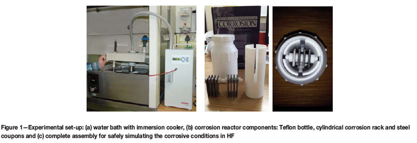
Each experiment was conducted in a 500 mL Teflon bottle which was placed in a water bath to maintain the acid at a constant temperature while corrosion of the coupons took place (Figure 1a). The coupons were assembled into a cylindrical rack (made of Teflon) which was placed upright in the bottle (Figure 1b). The HF was then poured into the bottle until the cylindrical rack holding the coupons (Figure 1c) had been completely covered. The bottle lid, with the 2 mm diameter drilled hole, was then screwed on. This allowed for the release of HF fumes in order to avoid pressure build-up in the Teflon container. The temperature was maintained at 25°C using an immersion cooler attached to the polypropylene lid, custom-made to cover the bath and which allowed the immersion cooler to hang freely in the water while being shielded from HF fumes by a polypropylene cylinder attached to the lid (Figure 1a). The lid over the water bath had a release valve in the open position, which channelled any HF fumes from the corrosion reaction to the extraction line of the fume cupboard, which led out to the KOH scrubber.
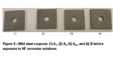
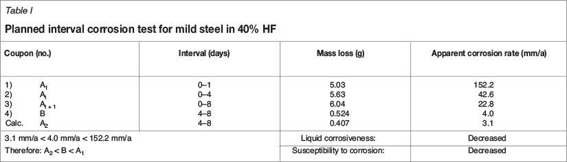
PICTs were allowed to run for periods of time experimentally determined by the planned interval tests of Wachter and Treseder in ASTM Standard G 31-72 (ASTM, 2009). Four coupons per bottle were introduced to a maximum of 500 mL HF. Subsequently, one coupon was removed from the corrosion rack at a specified time; this continued over the entire duration of a corrosion experiment, until all coupons had been removed. This was done to establish the metal samples' susceptibility to corrosion, the liquid's corrosiveness and the rate of the corrosion reaction under the simulated conditions. Following this standard method, the fourth coupon (B) was placed into the HF corrosion solution at the same time that the second coupon (At) was removed and allowed to corrode with the third coupon (At+j) for the remaining four days. In this way, comparing the corrosion rate measured for coupons 3 and 4, a change in the liquid corrosiveness could be compared to the criteria set out in the ASTM practice. In the same way, the susceptibility of the mild steel to the HF corrosion solution was determined by comparing the corrosion rate determined for coupon B to that of coupon A2 (Tables I-III). The mass loss for coupon A2 was determined by subtracting the mass losses of coupons At and At-1 and the corrosion rate determined using the average density of the coupons in that batch (e.g. coupon 1-4 in Table I).
Each time a coupon was removed from the bottle, it was rinsed with water and air-dried before storage in a desiccator. After testing, the corrosion products were removed from the coupons by ultrasonic cleaning for 30 minutes, followed by mechanical cleaning with a steel brush to ensure complete removal of the scale from the coupon prior to weighing. To calculate the corrosion rate (CR) in mm/a from metal loss the following equation was used:

where W = weight loss (in mg), ρ = density (in g/cm3), A = area (in cm2) of the coupons exposed to HF over time (in hours) based on ASTM Standard G31-72 (2004). The convention is to measure corrosion rate in mils penetration per year (MPY) (Jones, 1996). However, the constant (in this case K = 87.6) is dimensionless and changes with the conversion to the desired unit (in this case mm/a) (Davis and ASM International, 2000).
In the PICTs, identical coupons were placed in the same HF solution in the 500 mL Teflon bottle. The temperature was kept constant at 25°C for the entire time (t + 1). The symbols A1, At, At+1 and B were used to represent the corrosion damage experienced in each test (ASTM, 2009). Subsequently, A2 was calculated by subtracting At from At+1.
Results
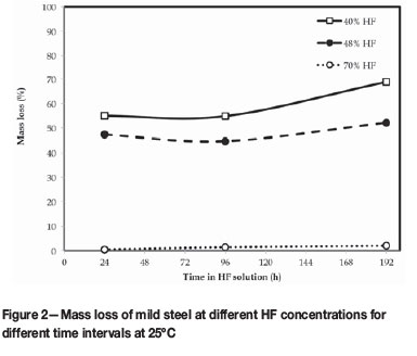
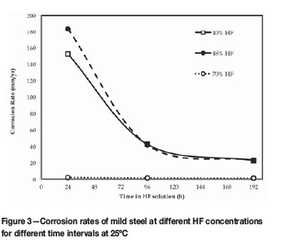
The data collected from the tests at different HF concentrations is shown in Tables I-IV and Figures 2-3.
When HF contacts mild steel, a corrosive reaction takes place:

whereby scale forms on the surface of the steel and inhibits further attack of the steel (Hansen and Puyear, 1996). Since this pre-passivation technique is applied in industry by allowing the storage tanks to be corroded by HF and HF fumes for 24 hours before commissioning (Jennings, 2007), the coupons in the PICT experiments were pre-passivated to represent the starting condition of the steel used in calculating the mass loss in each case. Equation [1] was used to calculate apparent density and the nominal density of 7.85 g/cm3 for mild steel was used throughout the study.
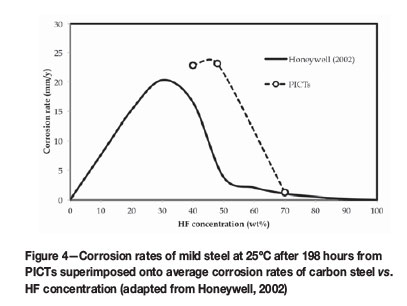
Honeywell Fluorine Products (Honeywell International Inc., 2014) is an HF supplier that documented the properties of HF to make technical and safety-related literature openly available in order to ensure safe usage of their products. From this literature, corrosion rates for carbon steel against HF concentration were provided and reported in MILS per year (1 MIL = 0.0254 mm). The values for average corrosion of mild steel were converted so that apparent corrosion rates from PICT tests measured after 192 hours could be compared (Figure 4).
Discussion
Planned interval corrosion tests
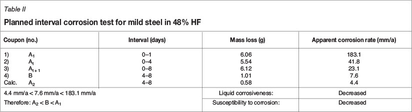
From the corrosion tests conducted with both 40% and 48% HF, the criteria set in ASTM Standard practice G 31-72 indicated that the corrosion rate for the calculated A2 value was smaller than the rate measured for B, and therefore the metal's susceptibility to corrosion decreased during the test. Moreover, coupon B had a smaller corrosion rate than A1, and therefore the liquid corrosiveness also decreased. This combined situation (A2 < B < A1) indicated that the 40% and 48% HF significantly decreased in corrosiveness during the test and the formation of a partially protective scale on the steel was likely (Tables I and II).
The 70% HF PICT fell under the same criteria as the 40% and 48% HF tests. However, the corrosion rates determined for A2, B, and A1 were significantly smaller (Table II). The A2 and B values determined for the more corrosive 48% HF (Table II) were nearly five times larger than the 0.9 and 1.5 mm/a corrosion rates determined for 70% HF under the same conditions. Therefore, the corrodibility of the metal was much lower in 70% HF than in 48% and 40% HF. Similarly, the initial corrosion rate determined for 48% HF was in excess of 180 mm/a and approximately 86 times faster than the A1 value for the 70% HF test. Therefore, the liquid corrosiveness of 70% HF was much less than was measured for the 48% and 40% HF PICTs. Irrespective of the safety risk aspects associated with 70% HF (van der Merwe, Cornish and van der Merwe., 2016), corrosion experiments with 70% HF produced slower, more steady corrosion rates and left an adequate portion of a coupon behind (<50% mass loss) for mass loss measurements after 8 days (Figure 2) to be best relatable to what was experienced in industry.
Effect of HF concentration
The lower the concentration of HF, the faster mild steel corrodes (Honeywell, 2002). This was shown in Figure 3. Notwithstanding that 48% HF was slightly more corrosive than 40% HF, the initial corrosion rate (over the first 24 hours) was much higher than for the 70% HF (2.1 mm/a). Thus, high corrosion rates (152-183 mm/a) were measured for HF below 50% concentration, despite the formation of the protective fluoride (FeF2) scale layer during the pre-passivation step. FeF2 is soluble in water (Perry, 2011) and since there was a higher water balance in the low-concentration acids, the scale readily dissolved and the mild steel substrate was attacked by fresh HF. However, with increased time, the scale did stabilize and the corrosion rate decreased to below 25 mm/a. The 70% HF was more conducive to scale formation on the mild steel and corrosion rates did not exceed 2 mm/a over the entire 8-day test (Figure 3).
The effect of HF concentration on the corrosion rate of mild steel after 192 hours (Coupon B, Tables I-III) was related to average corrosion rates reported in the Honeywell (2002) special chemical edition, where hydrofluoric acid properties were summarized (Figure 4). On average, lower HF concentrations (between 5 and 50% HF) resulted in significantly higher corrosion rates (>20 mm/a), while higher HF concentrations (>50% HF) corroded mild steel significantly slower (<2 mm/a). PICTs conducted over the HF range of 40% to 70% showed a similar trend to Honeywell (2002) (Figure 4), although the peak appeared to shift to the right, with 40% to 48% HF producing the highest corrosion rates. However, corrosion experiments at HF concentrations below 40% were not conducted, therefore this peak shift could not be substantiated. Moreover, the corrosion rates measured differed significantly as the exact corrosive conditions (initial condition of the coupons, temperature, pressure and volume of HF used) were not known and therefore could not entirely be reproduced.
Observations
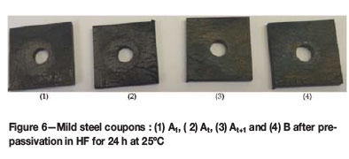
The corrosion solutions and coupons were observed over 8 days. Of the corrosion products (scale layer on coupons, corrosion solution and precipitates collected at the bottom of the bottle), only the corrosion solution was analysed. The coupons showed a heavily oxidized surface after pre-passivation (Figure 6). Iron fluoride (FeF2) has a grey colour, while the ferric hydroxide (FeF3.3H2O) has a recognizable yellow-brown colour (Haynes, 2016). The black colour is characteristic of oxidation (iron II/III oxide) of the steel (Haynes, 2016), as the corrosion reaction was allowed to take place in a well ventilated bottle. A combination of all these coloured substances formed the scales on the coupon surfaces and contributed to the unique colours visible when the coupons were removed and dried after pre-passivation (Figure 6).
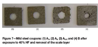
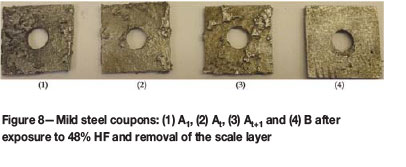
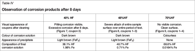
The results in Table IV and images of the cleaned coupons after each test, differed significantly depending on the initial concentration of the HF in the corrosion solution (Figures 7-9). Pitting-type corrosion was present over the entire surface of the coupons exposed to 40% HF (Figure 7). The 48% HF resulted in a visibly more aggressive attack over the entire surface of the coupons, reminiscent of uniform corrosion. The lower iron concentration (approx. 0.7% Fe) in the 48% HF corrosion products indicated that more iron was present in the solid scale layer and precipitate compared to the 40% test (approx. 2% Fe). Therefore, in the 48% HF test, the HF was forming more scale on the coupon surface which broke off and fell to the bottom of the reaction bottle, allowing HF to uniformly attack the freshly exposed steel surface and form scale to repeat the corrosion process (Figure 8). In contrast, the corrosion mechanism in the 40% HF was a visible pitting action (Figure 7), which penetrated through the passivation scale and aggressively kept corroding under the scale previously formed, resulting in the highest mass loss over the entire period (Figure 3).
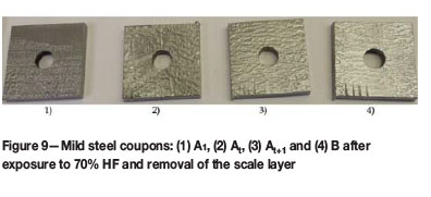
No scales were found at the bottom of the Teflon bottles of the 70% HF tests and the colour of the corrosion solutions remaining almost unchanged from the initial HF introduced (Table IV). The iron concentration analysed in the corrosion solution was less than 0.02%, with little HF being consumed over the entire test period (<1.5% HF). Here, the scale layer formed during the pre-passivation (Figure 9) succeeded in protecting the mild steel from further corrosion and produced a surface visibly free from corrosion, once the scale had been brushed off (Figure 9).
Conclusion
Corrosion results on SA 516 Gr 70 normalized mild steel indicated that HF concentrations below 48% were capable of producing corrosion rates above 180 mm/a. Conversely, the steel coupons placed in 70% HF corroded significantly slower (<2 mm/a after 8 days) and the corrosion rates were more closely related to those experienced in industry.
Acknowledgement
The Department of Science and Technology and the National Research Foundation are thanked for financial support. The South African Nuclear Energy Corporation Ltd. is thanked for time allowed for completing this article, as well as the Nuclear Materials (NM) and the Organic Fluorine Chemistry (OFC) sections within the Applied Chemistry (AC) department, in the Research and Development Division at Necsa, for the use of their facilities.
References
Andersen, T.N., Vanorden, N. and Schlitt, W.J. 1980. Effects of nitrogen oxides, sulfur dioxide, and ferric ions on the corrosion of mild steel in concentrated sulfuric acid. Metallurgical Transactions A,vol. 11, no. 8. pp. 1421-1428. [ Links ]
ASTM. 2009. G 31-72, standard practice for laboratory immersion corrosion testing of metals. Annual Book of ASTM Standards. ASTM International, West Conshohocken, USA. [ Links ]
Baboian, R. 2005. Corrosion tests and standards: application and interpretation. ASTM International, West Conshohocken, USA. [ Links ]
Nickel Development Institute. 1988. Cleaning and descaling stainless steels. Designers' Handbook Series. Toronto. [ Links ]
Craig, B.D. and Anderson, D.S. 1994. Handbook of Corrosion Data. ASM International, Materials Park, Ohio, USA. [ Links ]
Davis, J.R. and ASM International (eds). 2000. Corrosion: Understanding the Basics. ASM International, Materials Park, Ohio, USA. [ Links ]
Hansen, D.A. and Puyear, R.B. 1996. Materials Selection/or Hydrocarbon and Chemical Plants. CRC Press, New York, USA. [ Links ]
Haynes, W.M. 2016. CRC Handbook of Chemistry and Physics, 94th edn. CRC Press. [ Links ]
Honeywell. 2002. Hydrofluoric acid properties. http://www3.imperial.ac.uk/pls/portallive/docs/1/7276108.PDF [accessed 10 May 2016]. [ Links ]
Honeywell International Inc. 2014. Honeywell hydrofluoric acid. https://wiww.honeywell-hfacid.com/literature/ [accessed 3 July 2016]. [ Links ]
Jennings, H. 2007. Materials for storing and handling commercial grades of aqueous hydrofluoric acid and anhydrous hydrogen fluoride (no. 24057). NACE International Publication 5A171 (2007 edn). Houston, TX. [ Links ]
Jones, D.A. 1996. Principles and Prevention of Corrosion. 2nd edn. Prentice Hall, Upper Saddle River, NJ, USA. [ Links ]
Perry, D.L. 2011. Handbook of Inorganic Compounds. 2nd edn. CRC Press, Sound Parkway, USA. [ Links ]
Valkenburg, E.G. 2012. HF ISO tanks corrosion evaluation. Confidential internal report: Part 1: PCM-OPSA60-REP-12007. Pelchem SOC Ltd, Pelindaba, South Africa. [ Links ]
Van der Merwe, R., Cornish, L.A. and van der Merwe, J.W. 2016. Corrosion safety risk assessment for testing in hydrofluoric acid. [African Corrosion Journal, in press]. [ Links ]
This paper was first presented at the AMI Ferrous and Base Metals Development Network Conference 2016 19-21 October 2016, Southern Sun Elangeni Maharani, KwaZulu-Natal, South Africa.

