


Services on Demand
Article
 English (pdf)
 Article in xml format
 Article references
Indicators

Related links
-
 Cited by Google
 -
 Similars in Google
Share

 Permalink
Journal of the Southern African Institute of Mining and Metallurgy
On-line version ISSN 2411-9717
Print version ISSN 2225-6253
J. S. Afr. Inst. Min. Metall. vol.116 n.8 Johannesburg Aug. 2016
http://dx.doi.org/10.17159/2411-9717/2016/v116n8a6
PAPERS - DIAMONDS CONFERENCE
Extension of the Cullinan Diamond Mine No. 1 Shaft underneath the existing operating shaft, with emphasis on rock engineering considerations
G. JudeelI; T. SwanepoelII; A. HolderII; B. SwartsII; T. van StrijpII; A. CloeteII
IConsulting Rock Engineer, GeoSindile, Johannesburg, South Africa
IIPetra Diamonds, Johannesburg, South Africa
SYNOPSIS
In 2012, Cullinan Diamond Mine began an expansion programme with the shaft deepening and development of access to the C-Cut 1 block at approximately 839 m below surface. The expansion programme is funded by a combination of bank loans and retained operating profit generated by the mine. Continuous production during deepening of the No. 1 Shaft, which is the rock hoisting shaft, was therefore critical for sustainability and efficiency as well as overall funding of the project. The deepening method, support design and verification, as well as learning outcomes pertaining to the extension of the No. 1 Shaft underneath the existing operating shaft are summarized, with emphasis on the importance of gaining some understanding of the shaft's host rock mass.
Keywords: shaft sinking, shaft extension, rock mass properties, field stress distribution, numerical modelling, support design.
Introduction
Cullinan Diamond Mine (CDM) is an underground block cave diamond mine located 37 km northeast of Pretoria in South Africa's Gauteng Province. CDM has been operated by Petra Diamonds since it was acquired from De Beers in July 2008. CDM, a successful and long-lived kimberlite-hosted diamond mine, has produced many of the world's largest and most famous diamonds, including a quarter of all diamonds over 400 carats (ct). It earned its place in history with the discovery of the well-known Cullinan Diamond in 1905. The kimberlite pipe still contains the world's second-largest Indicated Diamond Resource. CDM is capitalizing on this by undertaking an expansion programme with the objective of taking production from just over 850 000 ct per annum (ctpa) to 2.4 million ctpa by FY 2019. The expansion programme is optimized by the extension of the CDM No. 1 Shaft beneath the existing operating shaft, allowing for normal production while the No. 1 shaft is extended.
The CDM expansion programme requires huge amounts of capital. The aim is to sustainably extend the life of the mine and therefore ensure extended socioeconomic community empowerment, employment opportunities, and stakeholder benefits from the mine for many years to come. The expansion programme is funded by a combination of bank loans and retained operating profit generated by the mine. Continuous production while extending the shaft was therefore critical for the sustain-ability and overall funding of the project.
Extending the shaft required the development of temporary excavations and leaving an in situ plug to enable safe sinking below the existing operating shaft. The host rock of the shaft deepening section consists of igneous rocks of the Bushveld Complex and Transvaal Supergroup metasediments, which are of a blocky nature due to their being intersected by four prominent joint sets. The Laubsher mining rock mass rating (MRMR) ranges between 21 and 80. The deepening section of the shaft is also subjected to varying field stresses brought about by the shaft's position relative to the open pit. The deepening method, support design, and verification as well as learning outcomes pertaining to the extension of the No. 1 Shaft are described, with emphasis on the importance of gaining some understanding of the shaft's host rock mass. This understanding of the rock mass in turn served to explain why the north-northwestern pit wall, where the No. 1 Shaft is located, is stable while the south-southeastern pit wall is not stable.
Mine layout
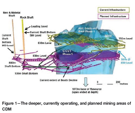
The kimberlite orebody is currently exploited by mining blocks BA5, BB1E, and AUC and BAW Phase 1. The new C-Cut Phase 1 block is located on the northwestern side of the kimberlite pipe with extraction planned on 839 Level, as illustrated in Figure 1. The upper portions of the kimberlite orebody have been depleted by open-pit mining activities, and current mining operations are concentrated between 630 m and 747 m below surface, where the block caving mining method is applied. In block caving, an undercut level is developed to allow the orebody to be undermined by drilling and blasting. When a sufficiently large area of the undercut level has been opened, i.e. an area covering a critical hydraulic radius, caving is initiated. This undercutting allows the rock to fracture and cave under its own weight. The caved ore is extracted from a level developed below the undercut, called the extraction level, through a series of systematic drawpoints by means of load haul dumpers.
No. 1 Shaft extension plan and execution
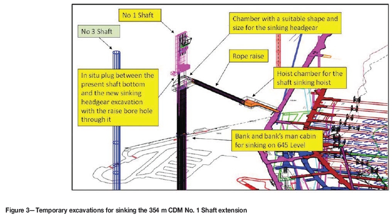
Mining of the new C-Cut Phase 1 block requires the CDM No. 1 Shaft to be extended by 354 m from its present depth of 580 m below surface to 934 m, while the existing shaft above it remains in operation (Figure 2). The circular 6.6 m final diameter concrete-lined No. 3 Shaft is also extended, but only by 75 m, and its extension is not dealt with in this paper. The No. 1 Shaft is a rectangular shaft and its extension will have minimum final dimensions of 9.6 m x 2.3 m after being lined with wetcrete. Sinking is made easier by a 2.5 m diameter raisebore hole, which was drilled from the new shaft bottom at 934 Level to the present shaft bottom at 580 Level (Figure 2). The raisebore hole served as an orepass, breaking point for blasting, and for ventilation during the sinking of the shaft extension. Sinking also required the development of temporary excavations and leaving an in situ plug to enable the safe sinking of the extension below the existing operating shaft (Figure 3). The temporary excavations include a hoist chamber for the sinking hoist, a rope raise, and a chamber of suitable shape and size to house the sinking headgear situated just below the plug. The excavation of the headgear chamber and deepening of the shaft commenced below the plug at 583 m below surface with the raisebore hole as access (Figures 2 and 3). Sinking progressed conventionally vertically downward towards 645 Level concurrent with sinking (winzing) of the rope raise at an angle towards the winder chamber (Figure 3). After the shaft and the rope raise holed, preparations commenced with permanent sinking arrangements to enable sinking to continue conventionally from 645 Level to 934 Level; the new shaft bottom (Figure 2). Silo development from the South Decline, which also forms an integral part of the No. 1 Shaft commissioning process, commenced concurrently with the sinking operations, and as a result of being ahead of schedule, early sinking of the No. 1 Shaft loading box on 895 Level could be done concurrently with the vertical sinking of No. 1 Shaft.

Shaft host rock - geological setting
The CDM No. 1 Shaft extension below 580 Level is located in igneous rocks of the Bushveld Complex and Transvaal Supergroup metasediments. Based on the C-Cut drill-hole data, the rock mass was characterized as follows.
► The country rock changes from Bushveld Complex norite to Transvaal Supergroup metasediments. The transition zone seems to be intercalated norite and metasediments at around 810 Level to 830 Level. Based on 736 Level exposures, the upper transitional quartzite contacts are welded and competent contacts
► The lower norite (including quartzite) is a competent rock mass with typical Bieniawski (1973) rock mass rating (RMR) values of 50-70 and uniaxial compressive strength (UCS) values ranging from 160 to 280 MPa, averaging 200 Mpa
► The metasediments are very variable, ranging from competent quartzite to shale/mudstone of low competency. The RMR values range from 30 to 60 and UCS values from 60 to 180 MPa, averaging 120 MPa.
Some of the CDM geotechnical average rock properties for the CDM No. 1 Shaft extension are presented in Table I.
Structural geology Joint sets
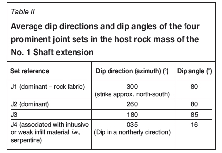
There are four prominent joint sets in the country rock mass, and hence also in the host rock mass of the No. 1 Shaft. These joints are also visible in many surface rock outcrops close to and further away from CDM. The average dip directions and dip angles of the four joint sets are shown in Table II and in Figure 4. The four joint sets were recorded and defined by SRK Consulting (2005).

Effects ofjoint sets on the shaft extension
Some effects that the orientations of the four joint sets have on the shaft are depicted in Figure 5. For example, some minor overbreak resulting from the very weak, slippery, and striated serpentine infill associated with J4 occurred on the eastern sidewall of the shaft (Figure 5). Some minor wedge failures also occurred as a result of dislodgement from between J1 and J3 on the eastern sidewall of the shaft, regardless of smooth wall blasting that had being practised (Figure 5).

In some vertical sections of the shaft, due to prominent joints of the J4 set, which dip at approximately 16° in a northerly direction, the shaft bottom on the southern side of the raisebore hole advanced more rapidly than the depth of the blastholes. In the same vertical sections of the shaft on the northern side of the raisebore hole, the advance per blast was less and normal blasthole sockets occurred in the shaft bottom.
Host rock classification by ground condition
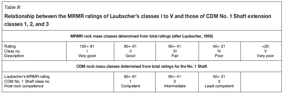
The host rock of the No. 1 Shaft extension was classified into three different categories, i.e. competent (1), intermediate competent (2), and least competent (3), using the mining rock mass rating (MRMR) system of Laubscher (1990). The MRMR system is based on joint spacing, joint infill, and degree of prominence of the joints etc. The relationship between the MRMR ratings of the Laubscher classes from I to V and the ratings of the three CDM classes is shown in Table III. For each of the three classes a different shaft support standard was designed to suit the different ground conditions. From the commencement of sinking, the standards have remained mostly unchanged, except for changing the anchor installations from a square pattern to staggered pattern and from welded square mesh to more robust expanded metal sheets, which have smaller apertures than the welded square mesh.
J-Block modelling
Construction of the J-Block model
J-Block software was used to simulate the effects of the four prominent joint sets, shown in Table II, on the CDM No. 1 Shaft extension without and with the shaft standard support. Since J-Block is generally used for horizontal to subhorizontal excavations, Esterhuizen (2015) pointed out that a vertical rectangular shaft can be modelled with J-Block when the shaft sidewalls are simulated to be dipping at 89°. The worstcase scenario was selected to model all the joints as having zero cohesion because of the presence of serpentine infill on the joint sets.
J-Block modelling results
The J-Block results indicate that even though the rockbolts reduce the number of unstable key blocks remarkably, compared to when no support is installed, there are still unstable key blocks of up to 0.002 m3 (approx. 25x10x8 cm) that could cause serious injuries if areal support is not used (Figure 6). The J-Block results also indicated that the eastern sidewall of the shaft has the highest probability of unstable key blocks, which corresponds with the observations shown in Figure 5.

Effects of varying field stresses
From approximately 679 m to 726 m below surface, excessive fracturing (typical dog-earing, as can be seen in Figure 7) of the eastern and western sides of the raisebore hole was observed. In this section, due to overbreak and scaling out of loose rocks - regardless of the smooth wall blasting that had been employed, the overall shape of the shaft changed from rectangular to almost elliptical, as can be seen in Figure 7 (as described by Judeel, 2014a). Below 726 m in the shaft extension, the ground conditions improved, again without excessive visible stress-induced fracturing. These observations indicated that the horizontal to subhorizontal field stress acting on the shaft was higher in the north-south direction than in the east-west direction. An investigation was carried out to determine the possible reasons for this.
Possible causes of the varying field stresses
In an attempt to find out and understand what caused the dog-earing, the following three reasons were considered.
1. The depth of the shaft where the dog-earing occurred, from 679 m to 726 m below surface, corresponds with the anticipated concentrated subhorizontal mining-induced stress field at the bottom corner below the open pit and block caves. Therefore, at the position of the shaft relative to the open pit and at depths from 679 m to 726 m below surface, this stress field can be expected to be acting in a north-south direction, which explains the dog-earing on the eastern and western sides of the raisebore hole as well as the shape to which the shaft scaled out to (Figure 7)
2. Due to the approximately north-south strike direction of the two most prominent joint sets, there may be high tectonic horizontal stresses acting in the NS direction, which could also explain the dog-earing on the eastern and western sides of the raisebore hole and the overbreak in the shaft. Stacey and Wesseloo (1998), who carried out an investigation of the in situ stresses in mining areas in South Africa, found that the major horizontal stresses are also oriented roughly in a north-south direction, which further confirms this reasoning
3. The dog-earing is probably due to the combined effect of the higher mining-induced and tectonic horizontal stresses, which both act in a north-south direction, as described under points 1 and 2 above.
Combined effects of the varying field stresses and poor rock mass conditions
Van de Steen et al. (2003) investigated the application of a flaw model to the fracturing around a vertical circular shaft. They found that dog-earing occurs when there is a variance of ±40% in the magnitude of the horizontal stress acting on a vertical circular shaft. Therefore, in the case of the CDM No. 1 Shaft extension, the magnitude of the stress acting in a north-south direction should be approximately 40% higher than that in the east-west direction. The extent of the dog-earing or the fracturing of rock around the raisebore hole, as well as around the rectangular shaft, depends on the stress magnitudes, geological rock mass conditions, and rock strength. However, the geological rock mass conditions have the most influence over the size or volume of the fractured rock around the raisebore hole and the shaft, since the stress-induced fracturing around the excavations follows the path of least resistance along joints in the rock mass. An example of this, lower down in the raisebore hole, can be seen in Figure 7. It is thus very important to classify the shaft host rock into one of the three rock mass classes as shown in Table III. and to select the corresponding support standard.
Modelling the stress distribution around the shaft
Two different field stress scenarios were simulated with Examine 2D to investigate and confirm the expected different induced stress distributions around the shaft. The horizontal stress magnitudes for the two field stress scenarios were also investigated by simulating a cross-section of the open pit. When considering the possible causes of the varying horizontal field stresses, as discussed above, and the geometry of the open pit, the determination of the field stresses that acts on the shaft with a two-dimensional modelling package may seem rather over-simplistic. However, since the aim of the modelling is mainly to investigate and confirm the expected different induced stress distributions around the shaft brought about by the two scenarios, it is reasoned that the estimated magnitudes of the field stresses, as shown below, will for this purpose be accurate enough.
► Possible scenario-East-west field stress (11 MPa) higher than the north-south field stress (6 MPa). Figure 8a shows the distribution of the induced stresses around the shaft calculated by Examine 2D-.
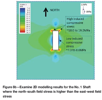
► Predicted scenano-North-south field stress (11 MPa) higher than the east-west field stress (6 MPa). Figure 8b shows the Examine 2D-calculated induced stresses around the shaft.

Discussion of the modelling results
Shaft
Since the shaft is a rectangular excavation it is not symmetrical in all directions, and therefore the magnitudes of the induced stresses are different for both the first and second scenarios, as can be seen in Figure 8a and 8b. The Examine 2D results indicate that the possible scenario, where the east-west field stress is higher than the north-south field stress, is the worst regarding the induced stresses around the shaft, i.e. it will cause high tensile stresses deep into the eastern and western sidewalls of the shaft, as can be seen in Figure 8a. At this depth below surface and with the present pit and mining geometry, all the indications are that the north-south field stress is higher than the east-west field stress, which results in a more favourable induced stress distribution around the shaft, i.e. all the induced stresses are compressive, as can be seen in Figure 8b. However, just to be on the safe side, the anchor lengths were verified for the possible situation (east-west stresses higher than north-south stresses, as indicated in Figure 8a). It was reasoned that should the possible scenario occur, it could cause the sections of the shaft host rock mass that were classified as having a class 2 or class 3 MRMR to deteriorate even further if it was not timeously supported with areal support, consisting of expanded metal cladding and wetcrete. According to the shaft support standards, these sections of the shaft's host rock mass, with a class 2 or class 3 MRMR, require the installation of anchor support. Figure 8a indicates that the anchors are long enough to extend past the modelled induced tensile stress zone. The SAIMM's referee of this paper pointed out that as the cave develops adjacent to the shaft that there is a possibility that the north-south stress component will reduce and that the east-west stress component may increase. The author agrees that this is indeed what can be expected as the cave develops and the depth of the pit increases. Therefore, the previously envisaged unlikely scenario becomes the possible scenario. This points out the necessity to investigate stress distributions in three dimensions; and hence to improve the level of confidence of the shaft support verification further, 3D numerical modelling is recommended.
Raisebore hole
The raisebore hole was also modelled with Examine 2D, and the results are shown in Figure 9a and Figure 9b. The modelling also indicates, as expected, that when the horizontal stress acting on the raisebore is higher in the north-south direction, high induced compressive stresses act on the eastern and western sidewalls of the raisebore hole. This confirms that in reality the north-south field stress from 679 m to 726 m below surface was higher than the east-west field stress, which caused the dog-earing on the eastern and western sides of the raisebore hole as shown in Figures 7.


Stability of the No. 1 Shaft regarding its location relative to the open pit
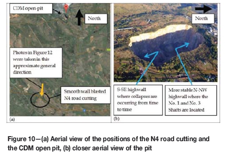
The south-southeastern pit wall had been unstable since before 2005, as described by SRK Consulting (2005) and Judeel (2014c). This led to the recent closure of a section of the R513 public road and a fuel service station, which were located close to the unstable south-southeastern pit wall. On the other hand, mine personnel reported that the north-northwestern pit wall, where the No. 1 Shaft is located, had been stable since the changeover from opencast to underground mining. This is evident from the fact that some remains of infrastructure that was used for the opencast mine are still intact on the edge of the north-northwestern pit wall. So the question arose; why is the north-northwestern sidewall, where the No. 1 Shaft is located, stable while the south-southeastern sidewall is not. This question led to the reasoning that the orientations of J4 and J3 are the main contributors to the instability of the south-southeastern pit wall, and that these orientations actually promote the stability of the north-northwestern pit wall, as described by Judeel (2015). As mentioned earlier, the joints as indicated in Table II are visible on many surface rock outcrops close to and further away from CDM. The most prominent surface exposure of the joint sets, especially J4, can be seen on the smooth wall blasted road cutting for the N4 Witbank (Emalahleni)/Pretoria Highway, which is located to the south of CDM (Figures 10, 11, and 12).


In Figures 11 and 12 wedge failures are visible, which occurred regardless of the smooth wall blasted road cutting due to rock wedges that slid down the joint surfaces of the J4 joint set and from between the more steeply dipping joints of the J3, J2, and J1 joint sets. The same type of wedge failure also occurs on the south-southeastern highwall of the open pit, but on a much larger scale due to the size and depth below surface of the highwall.
It is clear from the sketch in Figure 13 that the orientations of J3 and J4 are causing rock wedges/blocks on the south-southeastern highwall of the pit to tend to slide out on the weak infill material of J4, while the same rock wedges/blocks on the north-northwestern sidewall are locked in by gravity on the slope of the highwall. The instability of the south-southeastern sidewall is thus caused by the unfavourable orientation of J3 and J4 as well as time-dependent deformation occurring on the weak infill material of J4 at the bottom of the pit, where the vertical stress increases with depth. The time-dependent deformation occurs when the weak infill material is pushed out from between the joint planes by the constant vertical stress at a given depth, which in turn causes the wedges/blocks bounded by J3 and J4 to start sliding and toppling from the bottom up on the south-southeastern highwall, resulting in an unstable slope as shown in Figure 13.

Conclusions
1. Even though some sections of the No. 1 Shaft extension are located in poor quality rock masses, caused by excessive jointing, the J-Block results indicate that the 2.1 m rockbolt support alone, i.e. without anchors but with areal support, is sufficient to support the shaft when the effects of the shaft's field stresses are not taken into account
2. This is also confirmed by the continuous monitoring of the wetcrete in the completed deepened sections of the shaft, as described by Judeel (2014b), which indicates that no fracturing of the wetcrete that may indicate support failure has been observed to date
3. The investigation of the possible varying field stresses that may be intersected by the shaft during deepening revealed that the magnitude of the north-south field stress is higher than that of the east-west field stress, which results in more favourable induced stresses around the shaft
4. Even in the possible event, due to the increasing depth of the open pit, that the shaft be subjected to a horizontal field stress that change at a later stage so that the magnitude of the east-west field stress is higher than that of the north-south field stress, which will result in unfavourable tensile stress in the eastern and western sidewalls of the shaft, the installed shaft support is still adequate
5. The favourable orientation of the J3 and J4 joint sets on the north-northwestern highwall of the open pit, where the No. 1 Shaft is located, results in a more stable slope compared to the south-southeastern highwall, where the orientation of the J3 and J4 joint sets is unfavourable, thus causing the south-southeastern highwall to collapse from time to time. This led to the recent closure of a section of the R513 public road and a fuel service station, which were located close to the unstable south-southeastern pit wall. At present, there is no other infrastructure close to this pit wall
6. It is generally accepted that the key to the successful execution of the project so far has been the collaboration and cooperation between the geotechnical and project teams and the disciplined execution of the plan. Some important learning outcomes are that most of the reactions of the rock mass to the excavations can be explained by and predicted from the characteristics of the major joint sets of the rock mass
7. An understanding of the induced stresses that are caused by the excavations, and the resulting stress fields to which other excavations are subjected, by initially two-dimensional investigations, and later progressing to three dimensions for an improved understanding, is also required to explain and predict the reactions of the rock mass.
Acknowledgements
The knowledge and skill of the project management team, under the leadership of Mr André Cloete, contributed largely to the successful execution thus far of the extension of the Cullinan Diamond Mine No. 1 Shaft beneath the existing operating shaft. The authors also acknowledge the permission of Petra Diamonds to publish this paper.
References
Bieniawski, Z.T. 1973. Engineering classification of jointed rock masses. Transactions of the South African Institution of Civil Engineers, vol. 15. pp. 335-344. [ Links ]
Esterhuizen, G.S. 2015. Personal communication. [ Links ]
Judeel, G. du T. 2014a. Support and numerical modelling recommendations for the No 1 Shaft in the areas where dog-earing of the raise bore hole is occurring. Report no. GS0003/28 rev 02. GeoSindile Geotechnical and Rock Engineering Services. Johannesburg, South Africa. 9 pp. [ Links ]
Judeel, G. du T. 2014b. Shaft host rock deformation monitoring procedure for No. 1 Shaft and No. 3 Shaft. Report No. GS0003/29 rev 02. GeoSindile Geotechnical and Rock Engineering Services. Johannesburg, South Africa. 5 pp. [ Links ]
Judeel, G. du T. 2014c. Cullinan Diamond Mine - R513 high wall stability and risk review. Report no. GS0006/1 rev 05. GeoSindile Geotechnical and Rock Engineering Services. Johannesburg, South Africa. 25 pp. [ Links ]
Judeel, G. du T. 2015. Cullinan Diamond Mine - No 1 Shaft deepening support and general shaft stability review. Report No. GS0003/41 rev 02. GeoSindile Geotechnical and Rock Engineering Services. Johannesburg, South Africa. 42 pp. [ Links ]
Laubscher, D.H. 1990. A geomechanics classification system for the rating of rock mass in mine design. Journal of the South African Institute of Mining and Metallurgy, vol. 90, no. 10. pp. 257-273. [ Links ]
SRK Consulting. 2005. East wall stability: Impact on the R513 road - Report on a geotechnical study of surface ground movements associated with pit sidewall failures. Report no. 352650. SRK Consulting. Johannesburg, South Africa. 54 pp. [ Links ]
Stacey, T.R. and Wesseloo, J. 1998. In situ stresses in mining areas in South Africa. Journal of the South African Institute of Mining and Metallurgy, vol. 98, no. 7. pp. 365-368. [ Links ]
Van de Steen, B., Vervoort, A., Napier, J.A.L., and Durrheim, R.J. 2003. Implementation of a flaw model to the fracturing around a vertical shaft. Rock Mechanics and Rock Engineering, vol. 36, no. 2. pp. 143-161. [ Links ]
This paper was first presented at the Diamonds still Sparkling 2016 Conference 14-17 March 2016, Gaborone International Convention Centre.

