


Services on Demand
Article
 English (pdf)
 Article in xml format
 Article references
Indicators

Related links
-
 Cited by Google
 -
 Similars in Google
Share

 Permalink
Journal of the Southern African Institute of Mining and Metallurgy
On-line version ISSN 2411-9717
Print version ISSN 2225-6253
J. S. Afr. Inst. Min. Metall. vol.116 n.8 Johannesburg Aug. 2016
http://dx.doi.org/10.17159/2411-9717/2016/v116n8a3
PAPERS - DIAMONDS CONFERENCE
Design and implementation of steeper slope angles on a kimberlite open pit diamond operation-a practical approach
A. Madowe
Gem Diamond Technical Services
SYNOPSIS
The steepening of slope angles on an open pit mining operation has a material impact on improving the economics of mining. Steepening of slope angles can also increase the risk of slope failure. Slope failures are inherently costly events, because they can be catastrophic, resulting in multiple fatalities, equipment damage, and temporary or permanent closure of a mine. The steepening of the basalt slope angles at Letseng Diamond Mine followed operational improvements that were introduced through improved blasting practices and geotechnical controls. The steeper slope design resulted in a 6 Mt/a reduction in the peak waste mining compared with the previous mine plan coupled with an increase in the net present value and life of mine. This paper is an outline of the steps that were taken at Letseng to increase slope angles in waste and the resulting improvements to the mine plan.
Keywords: slope stability, slope design, mine plan.
Introduction
Letseng Diamonds (Pty) Ltd is a mining operation situated at Letšeng-la-Terae in the Kingdom of Lesotho (Figure 1). Gem Diamonds at 70% is the majority shareholder with the remaining 30% shareholding held by the Government of Lesotho. Letseng is known for producing large, top colour, exceptional white diamonds, with the highest percentage of large (+10.8 carat) diamonds of any kimberlite mine, making Letseng the highest average dollar per carat kimberlite diamond mine in the world. Letseng production is characterized by a uniquely high proportion of D colour type II diamonds, which are the purest form of diamonds. Historic stones from Letseng include 550, 478, 603, 493 and 601 carat diamonds.

Letseng employs a conventional open-pit mining method. Mining and ore treatment are on a continuous two-shift cycle. Drilling, loading, hauling and dewatering are operated by a mining contractor while blasting is done by the owners of the mine. Treatment plants are operated and maintained by a contractor while the Diamond Recovery Plant is owner-operated.
Geology
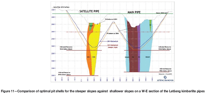
Letseng has two kimberlite pipes (Main and Satellite) adjacent to each other, with cone-shaped sections to confirmed vertical depths of 798 m and 849 m respectively (Figure 2).
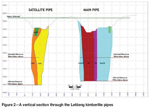
The surface impression of the Satellite Pipe is approximately 5 ha including a large basalt raft. The Satellite Pipe comprises two phases of kimberlite, namely North Volcaniclastic Kimberlite (NVK) and South Volcaniclastic Kimberlite (SVK). The Main pipe is approximately 17 ha, consisting of three kimberlite phases: KMain, K6, and K4. Letseng's pipes are near vertical and hosted in unweathered basaltic lavas. The kimberlites have sharp contacts with the basalt country rock and are characteristically carrot-shaped in section, comprising volatile-rich, potassic, and ultrabasic igneous rocks.
The Letseng mineral resource consists of approximately 5 million carats at an average value of over US$2 000 per carat. The resource is classified into Indicated and Inferred with the Indicated category extending from surface to 504 m below the datum elevation - Figure 2. 63% of the Letseng mineral resource is Indicated with the balance being Inferred.
Slope stabilitiy risk management at Letšeng
The steepening of the slopes angle in waste was enabled by operational improvements in the areas affecting pit slope stability. This section provides an overview of these improvements.
The purpose of slope stability risk management is to assist in providing a safe working environment for the open pit mining operation by managing the geotechnical risk. Letšeng seeks external assurance from world-renowned geotechnical consultants on the determination of the optimal slope designs for the pits.
Aspects of the Letseng slope stability risk management are as follows:
► Hazard identification--involves a range of geotechnical monitoring activities comprising instrumentation, survey, and visual inspection by geotechnical personnel. Lidar scanners were purchased for the purpose of monitoring slope deformation that might not be picked up by visual observation. Hazard plans are used to define potentially hazardous situations in the pits
► Exposure assessment-involving a study of historical trends from monitoring and comparisons with predicted performance from the geotechnical models
► Consequence assessment-with respect to safety of personnel and equipment in the pits is determined with reference to assessment of the impact and severity of the risk from the identified hazard
► Mitigation-involves a range of options such as evacuation, buttressing (construction of berms), installation of ground support, changes to pit designs, as well as installation of survey prisms and utilization of scanners to monitor the identified high-risk areas
► Standardized procedures--covering aspects such as data collection and record management, operation of lidar scanners, mining practices, evacuation, working under highwalls, and pit design changes. The procedures include a 'Code of Practice to combat rock fall and slope instability accidents at Letšeng Diamonds'.
Pit slope management
The management of the slopes is enforced throughout the mining operations. Discussions and necessary recommendations on operational procedures and awareness of identified geotechnical hazards are made in the form of verbal and written reports. The discussions take place in daily production meetings as well as monthly pit safety meetings.
Geotechnical data collection
The stability of an excavation is dependent on the rock strength and rock mass quality in which it is located. Geotechnical data is collected routinely through face mapping, core logging, and field and laboratory sample testing. The data, comprising uniaxial compressive strength measurements, spacing, orientation and condition of discontinuities is used for rock mass characterization and slope stability analysis. Detailed structural mapping on final walls is undertaken along each face that is exposed and updated onto the geotechnical database. Intact rock strength plays an important role in rock mass characterization, thus a comprehensive rock test database improves the confidence in the rock mass characterization. A geotechnical model has been created from the geotechnical field data and the interpolated geotechnical parameters, calculated slopes angles, and blasting parameters.
Sign-off of pit walls
Once loading has taken place close to a highwall, a sign-off form is filled out by the geotechnical personnel. There are two forms which are available to be signed off. The red form is filled in when the area does not comply with the geotechnical standards. The blue form in is filled when the area has passed geotechnical standards. The purpose of the sign-off form is to ensure that the highwall on the previous bench is clean and stable before proceeding to the next bench.
Pit monitoring
Visual inspections
Visual inspections are carried out to evaluate appropriateness of the slope design and to identify areas of potential rockfall. Visual inspections around working areas in the pits are carried out daily by geotechnical personnel and Pit Superintendents. The geotechnical engineer conducts detailed inspections in the areas of high risk and after falls of ground for back analysis. A monthly inspection is carried out by geotechnical personnel and Pit Superintendents to build a monthly hazard plan, which provides an indication of areas of potential geotechnical risk. An inspection around the perimeter of the pits is carried out once a month to identify new cracks and monitor old cracks around the pits should they develop during the month.
Monitoring instrumentation - scanners
Monitoring of the pit walls using the scanners is a quantitative method to supplement the qualitative methods described. Letseng introduced pit scanning to monitor progressive slope movements. The scanners have the capability to detect small-scale slope movements in the order of millimetres. It is now known that it is these small-scale movements characterized by temporal evolutions ranging from several hours to several weeks, that usually precede large slope failures in open pits. A procedure for the operation of the scanners was developed that among other issues, stipulates the necessary response in the event that rock movement is detected. These responses include visual inspection to determine cause of movement, increasing the frequency of monitoring, and in the event of continued acceleration of movement closure of the pit until the situation is fully investigated. The capability of providing advance notice of impending instability conditions through accurate and timely measurement of precursors to slope collapses clearly represents an outstanding benefit for the pit personnel.
Blasting
The release of energy during blasting produces reactive forces that may cause the deterioration of the rock face behind the mine design line. Blast damage is created by the transfer of explosive energy into the rock mass resulting in the propagation of fractures. Pre-splitting, trim and buffer blasting are the key blasting techniques adopted at Letseng to protect the final walls. The main parameters within the control of the blasting engineer are type and amount of explosive energy in a hole, drill pattern design, hole depth, hole diameter, hole angle, bench geometry, and blast timing. The correct parameters to use at Letseng mine has been determined through the application of theory, experience, consultations with renowned blasting experts, and trials on the mining faces.
A short-term mining plan developed and updated weekly includes of the schedule of activities and time required for wall control blasting. The mine planner ensures that pre-split lines are marked in accordance with the approved cutback design from the long-term planner.
Pre-splitting
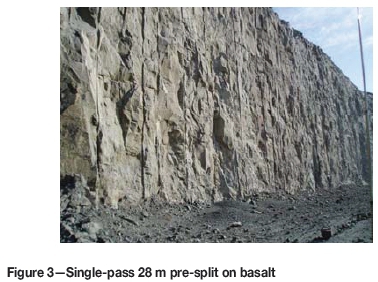
Pre-splitting is one of the key techniques applied at Letseng to protect mine design walls. Pre-splitting provides a preferential fracture plane behind the blast to terminate cracks emanating from blast-holes (Cunningham, 2000). Pre-splits have been designed in accordance with the signed-off geotechnical recommendations for a double bench of 28 m in waste, and single bench of 14 m in kimberlite. The Letseng pre-splits were designed on 1.0 m spacing between holes with a 1.0 m sub-drill. The pr-split holes are blasted ahead of production holes. Caution is taken while loading explosives (emulsion) in wet holes to prevent primers floating above the explosive charge, thereby resulting in misfired holes and frozen pre-splits. The blasts of pre-split holes are initiated simultaneously using detonating cord that has a detonation speed of more than 6 km/. Figure 3 shows a typical highwall face at Letseng mine for a double bench pre-split.
Trim and buffer blasting
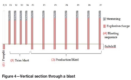
Trim and buffer blasting techniques are aimed at reducing the rate of energy release against the mine design wall. Trim blasts are designed along the excavation limit at reduced pattern and charge mass, and timed to achieve single-hole firing. Timing delays should be 'long enough for the strain waves from neighbouring holes to disperse individually' (Cunningham, 2000). Trim blasts at Letseng are marked at a 4.5 m burden and 5 m spacing on a rectangular pattern after which the production holes continue with the burden and spacing of 5.0 x 6.0 m on a staggered pattern. The minimum width of a trim is 20 m and the length generally limited to 100 m. Figure 4 illustrates the layout of a typical waste rock blast at the Minm. The sequence of blasting starts with the firing of the presplit line, followed by the firing and mining of the production blast, after which the trim is blasted and mined.
In cases where the geometry of the pit does not allow for a trim blast, a buffer/cushion blasting technique is applied. The first two rows of the production blast along the excavation limit are charged at reduced charge mass and drilled at reduced hole spacing to cushion/buffer the final wall from damage by the heavily charged production holes. At the mine, the first buffer line is designed with the standoff position of 1.6 m from the pre-split at blast-hole spacing of 2.5 m. The second buffer line is designed at burden and spacing of 4.0 x 4.0 m.
Electronics in blasting
Damage of highwalls is maximized when the maximum number of holes is detonated simultaneously. Timing is the key to controlling both the rate at which the available energy is released, and the direction of thrust of the blast. Cunningham (2000) states that the lack of precision of pyrotechnic timing systems requires the use of fairly long inter-hole delays to avoid crowding or out-of-sequence shots. He further notes that these 'long delays can result in ground movement interfering with the functioning of holes around each shot, and in excessive fracture and movement between shots'. The application of electronic blasting at Letseng is aimed at achieving more precise timing in comparison to pyrotechnic timing. The blasting engineers at the mine utilize electronic detonators to achieve faster timing between holes and slower timing between rows than pyrotechnic blasting initiation systems can achieve. The use of electronic detonators at Letseng allowed enhanced precision on blast timing, thereby protecting highwalls against blast damage and contributing to slope stability.
Highwall scaling
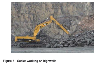
The purpose-made scaler at the mine is a standard CAT-385 excavator with two major modifications: a longer arm for greater reach and the replacement of the excavator bucket with a ripper for a CAT-D8 dozer for use as a prying tool. The scaler, with a reach of 15 m, is used to dislodge loose rocks on bench faces. This machine forms an integral part of the mine's slope stability management. Figure 5 shows the scaler dislodging loose rocks from highwalls and also removing rocks that are occasionally frozen onto the pre-splits. Due care is taken in the scaling operation to ensure the safety of the machine and operator in the cab.
Slope design
Geotechnical rock mass characterization
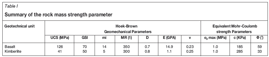
The basalt host rock at Letseng mine is generally competent with relatively widely spaced joint sets. Based on drilling records and observations in both pits, it is apparent that the basalt reports as a relatively dry unit with little or no risk of high pore-water pressures (Terbrugge, 2015). The estimation of the rock mass strengths and joint strength parameters was based on the geotechnical borehole logs, in-pit mapping, and the results of the laboratory testing programme carried out for the stability analysis conducted in June 2012 by SRK Consulting. A summary of the rock mass strength parameters from geotechnical borehole logging and laboratory testing is presented in Table I. These parameters were used in the slope stability analysis.
Slope stability analysis
The stability analysis was based on the Hoek-Brown criterion, which was used to represent the strength of both the basalt and the kimberlite rock units (Terbrugge, 2015). The criterion starts from the properties of intact rock and then introduces factors to reduce these properties on the basis of the characteristics of joints in the rock mass and geological observations (Hoek, Carranza-Torres, and Corkum, 2002). The estimation of joint strength parameters was based on the Barton-Bandis criterion, which enabled the estimation of equivalent Mohr-Coulomb friction angles and cohesive strengths of each rock mass. The analysis of sensitivity of the rock slopes, as well as the evaluation of the overall stability of the slopes, was carried out with the program SLIDE from Rocscience based on the limit equilibrium method. The results were verified with a stress deformation analysis using the program PHASE 2 using the shear strength reduction technique in the finite element model.
Limit equilibrium analysis
Limit equilibrium analysis is used to determine the stability of sliding planes, blocks, and wedges for a single free body and does not depend on the distribution of effective normal stresses along the failure surface. Limit equilibrium methods are relatively easy and fast to use, and also consider rock mass or step-path type failures.
Stress deformation analysis
The deficiency in limit equilibrium analysis of a jointed rock mass is that the analysis cannot quantify deformation and/ or displacement of the failing rock mass, which of course can be modelled by numerical methods that include the complex conditions found in rock slopes such as nonlinear stressstrain behaviour, anisotropy and changes in geometry. Numerical models divide the rock mass into elements, with each element assigned an idealized stress-strain relation together with the properties that describe the rock mass behaviour. Elements may be connected in a continuum model or separated by discontinuities in a discontinuum model, which will allow slip and separation at explicitly located surfaces within the model.
Recommended slope design
The main objective of the geotechnical slope design is to design fully optimized slopes at all stages of the mining operation utilizing available geotechnical data. The results of the limit equilibrium and stress deformation analysis all appeared to meet the acceptance criteria with a factor of safety greater than 1.3. Based on the geotechnical analysis, Figure 6 illustrates the recommended slope design in waste rock (basalt) for Letseng pit designs.
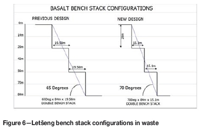
The 15.1 m berm was regarded as the minimum with respect to a rockfall that could report to the berm from a 28 m high bench. The new 2015 slope design in basalt resulted in a 5° steepening of the inter-ramp angle from the 2012 basalt slope design. The 84 m double bench stacks are separated by ramps or 25 m catchberms in the absence of a ramp.
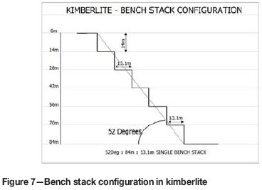
Figure 7 shows the slope geometry with a 52° stack angle in kimberlite. This design has remained unchanged as the steepening of slope angles was to be carried out only in waste.
Incorporation of steeper slope design into the mine plan
A review of the mine plans was required to evaluate the economics of the new pit slope angles. At the beginning of the Life-of-Mine (LoM) planning process, a 'Mine Planning Input Parameters' document is created as a repository of the mine design and planning input parameters.
The mine planning inputs
► The latest geological model that defines the grades, diamond price per kimberlite phase and tons of the various rock types in and around the deposit. The geological model also defines the classification (measured, indicated or inferred) of the various blocks in the model in accordance with the SAMREC Code
► Pit slope design parameters such as bench height, berm width and batter angles
► Financial data consisting of exchange rates, annual diamond price escalations, royalties, marketing and selling costs, discount rate, mining and treatment unit costs, overhead (fixed) costs, and capital costs
► Haul road design, minimum mining widths, mining dilution, and mining recovery. The minimum mining width is the minimum cutback width that allows the selected fleet to operate efficiently
► Plant recovery and annual plant capacity
► Any other relevant parameters such as environmental, legal, social, and governmental factors.
The inputs are compiled in collaboration with heads of relevant departments, which include finance, MRM, mining and the treatment sections of the mine. The input document is signed off before the parameters are used for mine planning. The consultative process and sign-off of planning parameters ensures that there is buy-in to the plan by all stakeholders. The evaluation of the economics of the new (steeper) slope design required the update of only the pit slope design parameters, all other parameters from the previous mine plan remaining unchanged.
Mine design
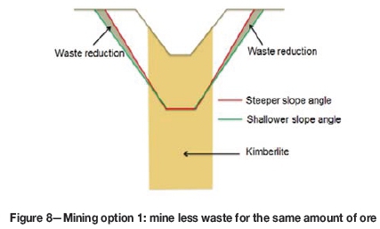
Mining options for a steeper slope - cost versus values
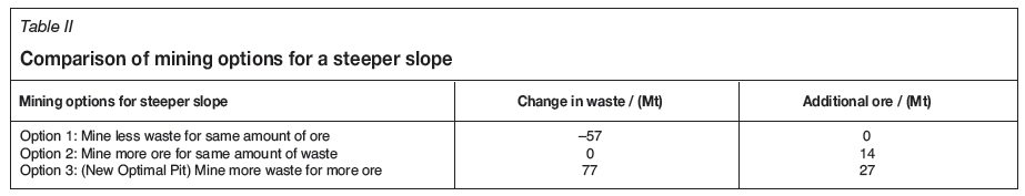
There are at least three mining options for a steeper slope angle. One obvious option is to save mining costs by mining less waste for the same amount of ore on the shallower slope, as illustrated in Figure 8.
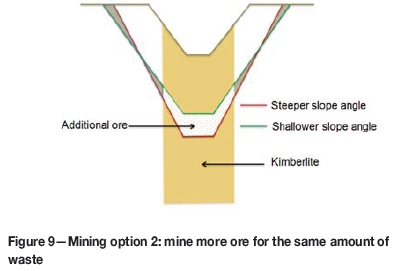
The second option, as illustrated in Figure 9, is to mine more ore for the same amount of waste.
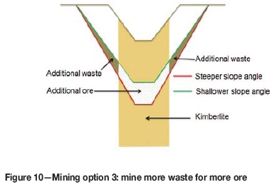
In a third option more ore is exposed by mining even more waste (Figure 10). This option makes better use of the difference in the cost of mining a ton of waste against the net value (excludes ore mining, processing and fixed costs) in a ton of ore. The net value in a ton of ore is much higher than the cost of mining a ton of waste, hence there is more value in mining more tons of ore than having a cost saving on waste.
Pit optimization
The mine design process starts with the update to the pit optimization exercise where a new optimum pit shell (Figure 11) is determined in Whittle software based on the steeper basalt slope angles. All other optimization parameters were kept constant from the previous optimization. The optimum shell was used as a guide in the pit design process. The optimization for the shallower slope, which formed the base case, yielded an optimal pit with 374 Mt of waste and 140 Mt of ore. Table II compares the pit optimization results for the three mining options for the steeper slope as discussed against the base case.
The value of a ton of ore at Letseng is approximately ten times the unit cost of waste mining, underlining the fact that accessing more ore is more valuable than saving waste. Consequently, mining option 3 yielded the highest NPV.
Pit designs
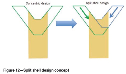
Pit design made use of the optimized/steeper basalt slope design parameters based on the stack angle of 70° in basalt and 52° in kimberlite over stack heights of 84 m. The major change from the previous design is the reduction of the berm from 19.58 m to 15.10 m. Pit designs were done using Gems software on a split shell design concept.
The split shell design subdivides the concentric cutback into two (or more) cutbacks as shown in Figure 12. The Letseng cutbacks are subdivided on a north-south split axis. The split axis was determined based primarily on the value distribution in the kimberlite pipes.
The fundamental advantages of this design concept include:
► Deferred waste mining and a reduced waste peak and hence an increased Net Present Value (NPV) of the mine
► Decongestion of mining operations through the separation of waste and ore mining activities leading to increased mining efficiencies and safer operations
► The elimination of waste spillage on ore ramps, thereby minimizing ore hauling stoppages and enhancing safety.
A disadvantage of the concept is merging of cutbacks, potentially leading to the development of bullnoses which can present stability issues.
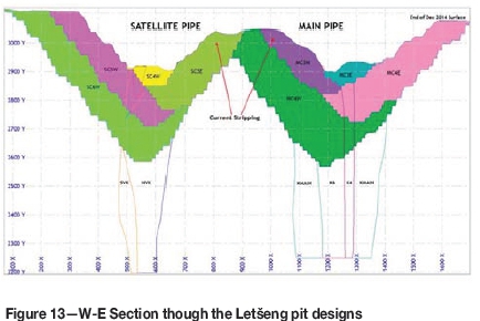
A section through the Letseng pit designs is shown in Figure 13.
Development of LoM schedules
Upon completion of pit designs, block model data constrained to different cutbacks is exported to XPAC software for the development of LoM schedule scenarios. The LoM plans have to satisfy conflicting objectives of maximizing NPV through deferring waste and ensuring the continuity of ore supply to the plants. This is achieved by planning through mining bottlenecks, keeping a minimum of six months of stripped reserves available. This is especially important during the time when the cutback being stripped starts to expose ore and the preceding cutback ore is nearing exhaustion.
Mine plan improvements
The schedule scenarios for the steeper slope and the shallower slope were input into the company NPV model for comparison. The LoM plan for the steeper slope design yielded the following improvements:
► Improved stripping ratios in the various pit cutbacks
► A reduction in the peak waste profile from 42 Mt/a to 36 Mt/a, leading to a significant reduction in fleet size
► The improved stripping ratios allowed for an increased ore contribution to plant feed from the higher grade Satellite pipe.
► A 14% improvement in the life-of-mine NPV
► An extension to the life of mine of three years.
Conclusions
The steepening of the slope angles in waste led to significant improvements in the mine plans and NPV. The steepening of the slopes was enabled through the improvements that were introduced in blasting, geotechnical controls, data collection and communication of geotechnical hazards.
► Improvements in blasting:
- The introduction and advances in trim or buffer blasting and pre-splitting around the final pit perimeter enhanced the protection of final pit walls
- Introduction of electronic timing systems in blasting led to improved blasting by exploiting the flexibility and greater accuracy of the electronic systems
- Introduction of multiple primers in blast-holes to improve fragmentation
► Improvements in geotechnical controls:
- The initiation of a process of geotechnical sign-off for each highwall immediately after completion of mining in order to ascertain that the wall has been mined to standard and will not pose future risks to mining personnel and equipment
- Improved geotechnical data collection that resulted in better rock mass characterization
- The introduction of slope monitoring using lidar scanners, including the formulation and adoption of a pit clearing procedure in the case of a detection of a slope movement beyond set threshold limits
- Commissioning of a purpose-built scaler for dislodging loose rocks on the pit highwalls.
However, the steeper slope requires the mine to be more vigilant in the areas of geotechnical control. An ongoing pit slope angle reconciliation on both basalt and kimberlite slopes will be required to be carried out on a regular basis, with decisions taken on the performance of the slopes and modifications to the slopes, as and when required. Quality assurance and quality control on the pit limit blast design patterns remain one of the most important factors in ensuring that the limit blasts are carried out in the most effective manner.
Acknowledgements
Thanks to my wife Fungai Kwangwari, to my colleagues, Bob Burrell, Obed Matlala, Dr Gerard Letlatsa, Nkopane Lefu, and Tinodashe Nyikavaranda, to SRK Consulting for their invaluable input, and to the Letseng management for giving permission for this paper to be published.
References
Akisa, D., and Gyimah, D. 2015. Application of Surpac and Whittle Software in Open Pit optimisation and Design. Ghana Mining Journal. pp. 35-43. [ Links ]
Armstrong, R. and Terbrugge, P. 2012. Slope design feasibility study for Letseng Diamond Mine, Lesotho. Johannesburg: Unpublished report. [ Links ]
Chiappetta, F. 2015. Letseng Blast Training. Maseru: Unpublished report. [ Links ]
Cunningham, C. 2000. The Use of Blast Timing to Iimprove Slope Stability (1st edn.). Colorado: Society for Mining, Metallurgy, and Exploration, Inc. (SME) Littleton, co. [ Links ]
Eberhardt, E. 2012. The Hoek-Brown Failure Criterion. Springer-Verlag. [ Links ]
Hoek, E., Carranza-Torres, C., and Corkum, B. 2002. Hoek-Brown failure criterion - 2002 Edition. Proceedings of NARMS-TAC Conference, Vancouver. University of Toronto. pp. 267-273. [ Links ]
Hustrulid, W., Kuchta, M., and Martin, R. 2013. Open Pit Mine Planning and Design. Volume 1 Fundamentals. CRC Press, Boca Raton, Florida. [ Links ]
Letlatsa, G., Madowe, A., Lefu, N., and Chitate, W. (2015). Slope stability risk management at Letseng. Letseng Diamond Mine internal document. [ Links ]
SAMREC. 2009. South African Mineral Resource Committee. The South African Code for Reporting of Exploration Results, Mineral Resources and Mineral Reserves (the SAMREC Code). 2007 Edition as amended July 2009. http://www.samcode.co.za/downloads/samrec2009.pdf. [ Links ]
Terbrugge, P. 2015. Proposed basalt slope angles. Johannesburg: Unpublished report. [ Links ]
Wooler, R. 2001. Taking Whittle Four-X to the limits. Proceedings of the Fourth Biennial Conference on Strategic Mine Planning Conference, Perth, 26-28 March 2001. Australasian Institute of Mining and Metallurgy, Melborne. pp. 163-169. [ Links ]
This paper was first presented at the Diamonds still Sparkling 2016 Conference, 14-17 March 2016, Gaborone International Convention Centre.

