


Servicios Personalizados
Articulo
 Inglés (pdf)
 Articulo en XML
 Referencias del artículo
Indicadores

Links relacionados
-
 Citado por Google
 -
 Similares en Google
Compartir

 Permalink
Journal of the Southern African Institute of Mining and Metallurgy
versión On-line ISSN 2411-9717
versión impresa ISSN 2225-6253
J. S. Afr. Inst. Min. Metall. vol.116 no.8 Johannesburg ago. 2016
http://dx.doi.org/10.17159/2411-9717/2016/v116n8a2
PAPERS - DIAMONDS CONFERENCE
The CCUT block cave design for Cullinan Diamond Mine
H. TukkerI; A. HolderII; B. SwartsII; T. van StrijpII; E. GroblerII
IUkwazi Mining Solutions, Johannesburg, South Africa
IIPetra Diamonds Group, Johannesburg, South Africa
SYNOPSIS
Petra Diamonds' Cullinan Diamond Mine (CDM) is currently producing from two mining blocks that are nearly depleted and highly diluted. CDM is developing the CCUT mining block as a mechanized block cave with an advance undercut that would replace the current mining blocks and increase production to approximately 4 Mt/a. The CCUT block production level on 839 m level is approximately 200 m below the current production areas on the 630 and 645 m levels.
The planning of the CCUT block with a lift height of approximately 194 m at CDM under Petra's ownership commenced in 2008. The access declines to the block started in 2009 and 2010. Most of the shaft deepening and waste development have been completed, with the planned 'deep' shaft and ground-handling system planned for commissioning in June 2016. The first undercut ring was blasted in July 2015.
This paper reports on the design process and evolution of the project, including:
► Geotechnical design criteria
► Advance undercutting sequence and strategy
► Undercut advance rates, slot designs, and rings designs to achieve the undercutting objectives (of high early tonnages and high undercut advance rates)
► The production level development philosophy in utilizing advance undercutting, production level design and drawbell opening sequence.
Keywords: block, cave design, advance undercut, rock mass characteristics, support regime.
History and background
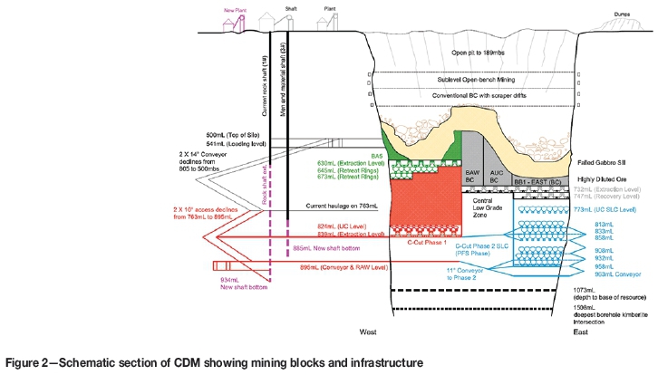
Premier Mine, as it was known then, was registered in 1902 and open pit mining activities commenced in 1903 (see timeline in Figure 1). The Cullinan Diamond, the largest rough diamond of gem quality in the world at 3106 ct, was found 9 m below surface (mbs) in 1905. De Beers acquired a controlling interest in Premier Mine in 1917 and open pit activities progressed down to 189 mbs. The mine closed during the Great Depression of 1932 and re-opened only after the Second World War. Dewatering of the pit began in 1945 and underground mining started in 1947 using variations of sublevel open-bench mining. Conventional-type cave mining started in the early 1970s, and sublevel open stoping was attempted in the early 1980s but was changed to mechanized panel retreat block caving. The BA5 and BB1E blocks (Figure 2) below the sill on elevations 630 mbs and 732 mbs respectively were changed from post-undercut panel retreat caves to advance undercut block caves to reduce the tunnel deformation and failures caused by high abutment stresses on the production level infrastructure, which was developed and constructed ahead of the undercut face. The BA5 block cave can be considered a success, with high extractions achieved, especially in the hard western Hypabyssal Kimberlite, albeit with significant tunnel failures in the softer Grey Kimberlite zones close to the contact. The BB1E and AUC mining blocks that lie within the soft eastern Brown and Grey kimberlites respectively experienced massive tunnel failures early in their lives and a recovery level on 747 mbs had to be established to recover the remaining BB1E resource tons (see Figure 2 ).
The mine was renamed Cullinan Diamond Mine (CDM) after the Cullinan Diamond as part of its centenary celebrations in 2003. Petra Diamonds acquired CDM from De Beers in November 2007. Petra initiated mining studies in 2008 to mine the CCUT resource defined down to 1073 mbs. Two declines to access the lower CCUT mining block were started in 2009 and 2010.
Historical production from CDM ranged from 2 to 5 Mt/a). More than 360 Mt of kimberlite ore have been mined to date over 113 years, yielding approximately 128 million carats at 35 carats per hundred tons (cpht). CDM has produced over 750 stones that are greater than 100 carats and more than a quarter of the world's diamonds that are greater than 400 carats in size. It is furthermore also the only significant source of blue diamonds in the world.
Current CDM mine infrastructure includes a rock shaft (No. 1 Shaft) for waste and ore hoisting from 541 m level (mL) and a men and a material shaft (No. 3 Shaft) that provides access down to 763 mL. Production from underground mining sections is currently from highly diluted block cave drawpoints on 747 mL and retreat rings on 645, 673, and 732 mL at a rate of approximately 2.6 Mt/a. 645 and 673 mL were old ventilation levels for the BA5 block and these levels were converted to longhole retreat production sections to serve as tonnage gap-fillers between the current blocks and the CCUT. 732 mL was the extraction level for the BB1E, AUC, and BAW blocks and the remaining production planned from these blocks will be retreat rings recovering the major apex pillars above the old production tunnels. BAW was abandoned due to the low grades reporting from this area.
With the current ground-handling system ore is loaded with load haul dumpers (LHDs) from production section and tipped into rock-passes from where it is trammed with locos and hoppers on 763 mL to the north and south jaw crushers. The two crushers feed two conveyors positioned on 805 mL that convey the rock to the top of the No. 1 Shaft silos at 500 mL. The loading level on 541 mL feeds the No. 1 Shaft loading flasks, from where rock is hoisted to surface. On surface, the ore is conveyed to the processing plant, which was constructed in 1947 but has been continuously modified and upgraded to recover large and small diamonds.
The CCUT project entailed establishing new surface and underground infrastructure to extract the next mining block below the depleted BA5 mining block using block caving with an advance undercut at a production rate of 4 Mt/a. This project required major recapitalization that included:
► Extending the existing shafts to provide access, services, and rock hoisting on the CCUT horizon as shown in Figure 2. This includes two new shaft bottoms, a loading level, pumping infrastructure, underground workshops, and underground stores
► No. 1 Shaft winder upgrade to increase the hoisting capacity to 4 Mt/a from 934 mbs
► Extending two declines down from 763 mL to the CCUT ground handling level on 895 mL
► A new block cave with undercut level on 824 mL (measurement from the undercut gives an effective lift height of 194 m to 630 mL), production level on 839 mL, and ground-handling on 895 mL, as shown in Figure 2.
Geology
The CDM kimberlite pipe has a kidney-shaped exposure on surface and measures 860 m by 400 m, elongated along a NW-SE axis. The surface area of the pipe is approximately 32 ha, decreasing progressively to 22 ha at 500 mbs and 12 ha at 1000 mbs. Subsidence caused by the mining operations has increased the surface rim size more than 40 ha. It has been estimated that the top 300 m of the original pipe has been removed by erosion since its intrusion 1 200 million years ago. The diatreme zone of the pipe is fairly unique in that it has been cut by a younger 75 m thick gabbro sill that dips shallowly from north to south between elevations 350 mbs and 525 mbs, as indicated in Figure 3. The country rock around the pipe consists of Waterberg quartzites, felsite, norite, and Transvaal Supergroup metasediments, as shown in Figure 3. Three major kimberlite intrusions have been identified within the pipe. Two of these are typical volcaniclastic kimberlites (previously identified as tuffsitic kimberlite breccia or TKB), while the final phase of intrusion is a hypabyssal kimberlite core complex in which four kimberlite types and late-stage carbonaceous dykes have been identified.
► Brown Kimberlite is a volcaniclastic kimberlite that has the highest clay content and is the weakest kimberlite at CDM. It represents the first intrusion and has the highest grade, which varies from 60-115 carats per hundred tons (cpht). It also contains diamonds with the highest average value
► Grey Kimberlite is also a volcaniclastic kimberlite, and can be classified as weak kimberlite with high clay content. This facies has the lowest grade and lowest value diamonds, especially close to the centre of the pipe where there is significant internal waste (the 'Grey Waste' sub-facies), and grades are estimated to be generally below 30 cpht. This area has remained mostly unmined below the sill due to its low payability
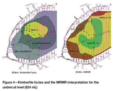
► The hypabyssal core is made up of Pale and Dark Piebald hypabyssal kimberlite surrounded by Black and Green transitional kimberlite. It is more competent than the two volcaniclastic kimberlite facies, with almost no clay content. This kimberlite is believed to be responsible for producing the majority of large (>100 ct) stones at CDM, including the Type 2a and blue boron-bearing Type 2b diamonds perceived to occur close to the internal Grey/Hypabyssal and Grey/Waste contacts on the western side of the pipe. The grade within this facies varies from 30-70 cpht. The project footprint consists mostly of the Hypabyssal Kimberlite core surrounded by Grey Kimberlite, as shown in Figure 4.
The late-stage carbonaceous kimberlite dykes at CDM are widespread and intrude into all kimberlite facies. In some cases where these dykes occur parallel to, or on, internal facies contacts and close to pipe contacts they can cause major instability in the form of shear planes that can fail uncontrollably if not supported timeously and correctly during the development phase.
Geotechnical setting and design parameters
Table I indicates the rock mass characteristics for the project area at CDM. Note that the uniaxial compressive strength (UCS) and the mining rock mass rating (MRMR) values for the Grey and Hypabyssal kimberlites have large ranges, and the average values indicate that the ground for the CCUT project should be fairly competent with minimal expected problems. The localized weak mining zones with lower-end MRMRs close to the pipe and internal contacts as shown in Figure 3 do, however, suggest that ground conditions pose a significant geotechnical risk if not managed properly, as experienced in the BA5 directly above the CCUT. The current generic tunnel support regime for the CCUT block includes bolts, sealant, welded mesh, and shotcrete. The contacts and drawpoints will have site-specific recommendations, usually including stiff brow steel sets.
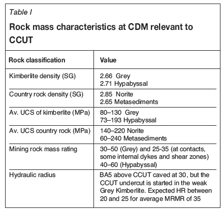
Figure 4 shows that the weaker (lower MRMR) areas are generally close to the contact zones, with the hypabyssal core being competent. All the undercut and production tunnels intersect the contact or weaker zones and the mine design, sequence, and tunnel support standards have to ensure that these areas stay open for the life of the production block. With this in mind a back-analysis was done on the AUC block cave, which is located in the Grey Kimberlite as shown in Figure 3. This block sat down halfway through the undercutting process and most of the undercut tunnels crushed within a short space of time. The process entailed simulating the mining steps that were followed in a geotechnical modelling package and calibrating the model until the results replicated the actual events that followed.
The model was then re-calibrated for CCUT conditions, including rock characteristics depth, pipe geometry etc. Different scenarios were designed, sequenced, and modelled to achieve the optimal outcome. Some of the model outcomes at different stages of undercutting and production drawbell construction are shown in Figure 5.
This paper does not report on the specifics of the geotechnical modelling, which are covered elsewhere, but focuses on the recommendations incorporated into mine design and schedule. The geotechnical recommendations were as follows:
► The undercut tunnels were sized to 4 m wide and 4 m high and the extraction level development to 4.2 m wide by 4.2 m high
► The El Teniente layout was chosen as the preferred block cave layout as this resulted in improved development efficiencies and quality while reducing the planned drawbell construction and opening times compared to the herringbone layout
► The undercut tunnel spacing of 16 m and production tunnel spacing of 32 m used in the modelling were found to be appropriate
► The extraction level drawpoint spacing of 16 m had to be increased to 18 m. It was furthermore recommended that the spacing be increased to 21 m for the last third of the footprint to avoid the deformation shown in Figure 5. Local underground observations will, however, guide geotechnical simulations and subsequent recommendations going forward
► The analysis shows that the undercut deformation was normal until undercutting was around 65-75% complete. The final corner showed significant levels of deformation due to the pipe geometry. Wrecking of the final problematic undercut zone might be an appropriate strategy, but observations going forward will dictate the final recommendations
► The southern contact appears to be problematic with fringing occurring (see Figure 5). The presence of a local shear zone is another complication that might amplify the problems highlighted by the modelling
► The initial undercut strategy, consisting of an advance undercut with production drifts and drawpoint stubs ahead of the undercut face, was revised to having only the first four tunnels (without any stubs) developed ahead of the undercut face. Of the remaining four tunnels, only every second tunnel can be developed ahead of the undercut
► Local ground conditions must be re-interpreted continuously and the mine design and sequence adapted accordingly.
Underground infrastructure
The CCUT project consists of three major levels: an undercut, production, and conveyor/ventilation (RAW) level. The main underground infrastructure entails:
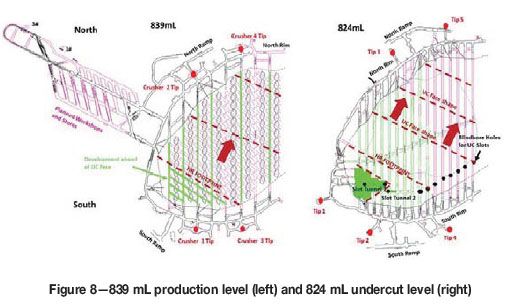
► Ground handling (see Figure 6 to Figure 8):
- 13 x 9 t LHDs (100 t/h or 33333 t/month per LHD) loading from development, rings, rim loading, and production level drawpoints. Total capacity of 13 LHDs is 5.2 Mt/a
- Undercut level: 4 x tips with 600 mm grizzly, rockbreaker, and orepass configuration, each feeding one of four crushers
- Production level: 4 x double-tip 600 mm grizzly, rockbreaker, and orepass configuration, each feeding one of four crushers
- 4 x 450 t/h (100 kt/month or 1.2 Mt/a each) jaw crushers positioned below the production level. Enough space was allowed above the crushers to introduce a recovery level if required without changing the ground-handling system materially
- 2 x 1200 mm strike conveyors (850 t/h or 3.6 Mt/a each) below the crushers convey the ore to the new shafts silos
- The No. 1 Shaft hoisting capacity of 4 Mt/a is the limiting factor on the ground-handling configuration
► Ventilation (see Figure 6 and Figure 8):
- The shafts and declines accessing the block facilitate air intake for the mining section. The dirty production air is directed from the production tunnels down raisebore holes to the return airway level (RAW level) on 895 mL. The dirty air in the RAW is then directed to the central return airpasses (RAPs) that link into the main mine returns
► Trackless maintenance and shaft logistics (see Figure 8):
- Temporary workshops constructed on 763 mL will serve until the new centralized workshop on 839 mL has been developed and equipped
- All the material will be dispatched via No. 3 Shaft to the 839 mL laydown area and store facility, from where it will be issued to mining crews
- Production personnel will access the production level via No. 3 Shaft on 839 mL
Undercut design and schedule
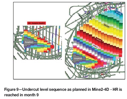
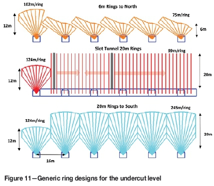
The weakest zone within the project area is the southwestern zone, as shown in Figure 4, with MRMR ratings below 40 and in some instances 30-35. The hydraulic radius (HR) for the area is estimated to be 20-25 m. In assessing the overall risk of undercutting the entire footprint, the decision was taken to initiate the undercut slot in the southwest to ensure that the higher risk area was undercut before the HR with associated high abutment stresses was reached. Initiating the undercut in the weaker ground would also allow for higher initial cave propagation and production rates. The undercut slot tunnel was positioned 30 m from the southwest contact to enable high undercutting rates towards the south and north to reach the HR footprint within the first nine months of undercutting, and by doing so reach the more competent zones early in the undercutting process as shown in Figure 9. The undercut face shape can be described as diagonal, with 6-8 m lead-lags being maintained while the face advances in a northeast direction. The lead-lags will also be adjusted in response to local ground conditions observed, especially close to shear zones, tunnel intersections, internal contacts, and pipe contacts. The rings advancing to the southern contact were initially planned to have a height of 12 m. However, to improve stability close to the contacts and to increase production capability, being close to the south tips, the required undercut height was increased from 12 m to 20 m on the south of the slot tunnel. The ring height on the northern side was reduced to 6 m, as shown in Figure 10, for the following reasons:
► Required longhole drilling metres: only 75 m per ring allows for quick drilling turnaround time
► Low probability of pillars with a low undercut and ease of ability to fix potential problems, i.e. large rings big problems and small rings small problems'
► Tonnage per ring reduced from almost 1500 t to approximately 500 t in situ considering the long tramming distance to the northern tips
► Low logistical requirements enabling high advance rates.
The average monthly required undercut advance rate is four rings (or 8 m) and the total output for the undercut per month is 48 rings, 1400-1800 m2, 17 000 t (at 60-70% draw of blasted tons), and approximately 4000 longhole metres with 10% re-drill. The powder factor using bulk emulsion is 0.75-1.0 kg/t for the undercut rings (2 m burden, 2-2.3 m toe spacing using 76 mm blast-holes).
Production level design and schedule
The production level has a tunnel spacing of 32 m and a drawpoint spacing of 18 m as shown in Figure 11. The production level construction strategy employed at the CCUT project entails constructing the drawbells within the HR footprint ahead of the undercut face, which includes the first 4 bell rows or 10 drawbells in total, while the abutment stresses are considered to be low.
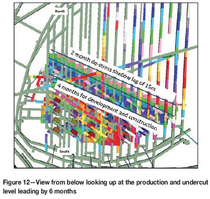
The remaining footprint will be constructed as an advance undercut that entails constructing only tunnels 1-4, 6, and 8 ahead of the undercut face and all the other drawbells and tunnels 5 and 7 in the de-stress shadow of the undercut face, as shown in Figure 8, to avoid abutment stresses damaging production level infrastructure. The re-compaction time guideline used in determining the construction cycles and resource requirements is 6 months, which is the time to open up a drawbell from the time the undercut advances over the area. Two months is required for the undercut moving at 8 m per month (16 m) to create the de-stress shadow, and another four months for development and construction (see Figure 12). If this timeline is not adhered to and the undercut runs away from the production level, the area already undercut might re-compact and the abutment stresses reconfigure over these zones and be transmitted down onto the production level.
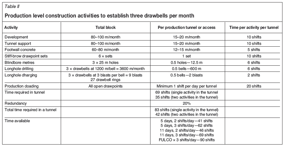
The training of the production level construction crews entails using the initial 10 drawbells inside the HR boundary as a school to acquire the appropriate skills to complete the required activities within a set sequence and timeframe. The activities include development, tunnel support, placement of footwall concrete, construction of stiff-brow sets, blindboring, longhole drilling, longhole charging, and production loading as shown in Table II. Most of these activities must occur within the space of one month in a production tunnel.
The individual activities and durations allowed for are not difficult to achieve, but the combination of all the required activities in a set sequence in one tunnel makes the scheduling extremely complex, rigid, and difficult to achieve. In an advance undercut scenario the emphasis is on tunnel utilization and not necessarily resource utilization or efficiency, which means that the activities have to be over-resourced at lower efficiencies to ensure that the required cycle is achieved. CDM has opted for a 5-day three-shift configuration and has populated its micro-schedules according to this shift configuration. This shift arrangement equates to 62 available shifts, an average of 1.5 activities per tunnel (with the focus on getting the ventilation in place to allow multiple activities in a tunnel, not all the activities can be carried out in parallel), and overtime to recover any slip in the schedule. The first 6 months will serve as a trial, and if required the CCUT crews can convert to a FULCO shift configuration as a last resort to ensure that the schedule is achieved.
Production level drawpoint maturity rules
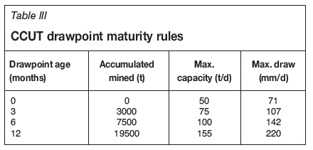
The expected fragmentation for the CCUT is 30% >2 m3 (oversize) initially and 7-12% >2 m3 after 20% draw. The maturity rules have been adjusted to allow for lower initial draw rates in the build-up and higher rates on reaching maturity to avoid excessive percentages of oversize that must be blasted or handled by the the grizzly. The drawpoint maturity rules as applied in mining scheduling software packages (Mine2-4D and PCBC) can be viewed in Table III. A total of 184 drawpoints will be in production at steady-state, allowing for sufficient redundancy when producing at a rate of 4 Mt/a.
Conclusion
CDM's CCUT block cave will be one of the deepest mechanized kimberlite block caves in production when it reaches steady state at 4 Mt/a in three years' time. The first undercut rings were blasted in July 2015 and the first drawbell will be opened in January 2016. The fundamentals of the mine design and schedule seem appropriate thus far, with development and ring blasting being on schedule, although problems were encountered in handling waste tonnage and getting the ventilation infrastructure in place. Future planning at CDM entails implementing more detailed micro-schedules in the production level construction environment to ensure that timetables are achieved on an hour-by-hour, day-by-day, and month-to-month basis. Up-skilling and build-up of specialized longhole, development, and construction crews is also a priority to ensure that the production level targets are achieved, thereby ensuring the successful tonnage ramp-up of the CCUT block.
Acknowledgements
The authors thank Petra Diamonds for allowing us to publish this paper, and in particular the CCUT project team at CDM. Contributions and technical input were provided by Andrew Rogers.
References
Bartlett, P.J. and Croll, A. 2000. Cave mining at Premier Diamond Mine. Proceedings of Massmin 2000, Brisbane, Queensland, 29 October - 2 November 2000. Australasian Institute of Mining Metallurgy, Melbourne. pp. 227-235. [ Links ]
Beck, D. 2010. Premier Mine Stability 824/839 Level. [ Links ]
Beck, D. 2014. Assessment of stability of proposed designs for CCUT Phase 1 and 2. [ Links ]
Laubscher, D.H. 1994. Cave mining - the state of the art. Journal of the South African Institute of Mining and Metallurgy, vol. 94, October. pp. 279-293 [ Links ]
Marsden, H. 2006. Observations of damage in the AUC undercut, Premier Mine. [ Links ]
This paper was first presented at the Diamonds still Sparkling 2016 Conference, 14-17 March 2016, Gaborone International Convention Centre.

