


Services on Demand
Article
 English (pdf)
 Article in xml format
 Article references
Indicators

Related links
-
 Cited by Google
 -
 Similars in Google
Share

 Permalink
Journal of the Southern African Institute of Mining and Metallurgy
On-line version ISSN 2411-9717
Print version ISSN 2225-6253
J. S. Afr. Inst. Min. Metall. vol.116 n.5 Johannesburg May. 2016
http://dx.doi.org/10.17159/2411-9717/2016/v116n5a12
PAPER - FURNACE TAPPING CONFERENCE
The tap-hole - key to furnace performance
L.R. NelsonI; R.J. HundermarkII
IAnglo American Platinum Ltd
IIAnglo American plc
SYNOPSIS
The critical importance of tap-hole design and management for furnace performance and longevity is explored through examining some of the specific matte, metal, and slag tapping requirements of non-ferrous copper blister and matte converting and smelting, ferroalloy smelting, and ironmaking systems. Process conditions and productivity requirements and their influence on tapping are reviewed for these different pyrometallurgical systems. Some critical aspects of the evolution of tap-hole design to meet the diverging process and tapping duties are examined. Differences and similarities in tapping practices and tap-hole management are reviewed. Finally, core aspects of tap-hole equipment and maintenance are identified -aspects that are considered important for securing improved tap-hole performance and life, so pivotal to superior furnace smelting performance.
Keywords: tapping, tap-hole, ironmaking, ferroalloy, non-ferrous, matte, slag, blister, smelting
Introduction
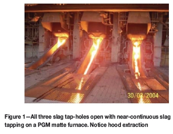
The sheer diversity of tapping configurations used on industrial pyrometallurgical operations is at first bewildering. They range from historical tilting furnaces without tap-holes to modern eccentric bottom tapping (EBT) tilting and/or bottom slide-gate electric arc furnaces; to classical single tap-hole multiphase tapping (e.g. metal/matte and slag); to dedicated phase tap-holes (e.g. dedicated metal/matte-only and slag-only); to dedicated phase multiple tap-hole configurations (up to eight metal/matte-only tap-holes and six slag-only tap-holes); to more esoteric metal/matte-only siphons and slag overflow skimming, e.g. Mitsubishi Continuous Process (Matsutani, n.d.). This can be further complicated by periodic batch tapping; consecutive tapping on a given tap-hole; alternating tap-hole tapping practice; near-continuous slag-only tapping, with discrete batch matte/metal tapping on higher productivity, but low metal/matte fall (<20% by mass feed) Co and Ni ferroalloy and platinum group metal (PGM) matte furnaces; near-continuous tapping through batch tapping of individual tap-holes that are opened consecutively (Tanzil et al., 2001; Post et al., 2003); to fully continuous tapping on coupled multi-furnace cascades (Matsutani, n.d.).
This is largely a consequence of differing processing conditions (process temperature, superheat (AT), Prandtl number, Pr = μCP/k, where μ = dynamic viscosity, CP= specific heat capacity and k = thermal conductivity, and resulting heat flux). But this can also be influenced strongly by industrial operating philosophy in terms of furnace design for campaign life longevity (i.e. greater capital expenditure for longer, say 20-30 years' life) versus furnace productivity (i.e. number of heats/campaigns to provide the greatest possible dilution of fixed costs per unit of commodity produced). And this may not even be consistent within a given commodity; all ironmakers (blast furnace (BF) campaign life-based) supply downstream steelmakers (who use heat/campaign-based converters and/or electric arc furnaces).
However, regardless of the specific tap-hole configuration or operating philosophy, owing to the addition of dynamic (often periodic) and more intense process conditions (exposure to higher temperatures leading to accelerated corrosion, greater turbulence, and elevated rates of mass and heat transfer) and higher concomitant thermomechanical forces (from thermal or flow shear stresses), furnace performance and longevity is intimately linked to tap-hole performance. For good reason Van Laar (2001) titled his paper 'The taphole: the heart of the blastfurnace' at the 2001 symposium entitled The taphole - the blast furnace lifeline (Irons, 2001), while the title of the 2010 Coetzee and Sylven (2010) contribution 'No taphole - no furnace' and the staging of the SAIMM Furnace Tapping conference in 2014 suggest continued criticality and relevance.
By first comparing and contrasting some of the process conditions and resulting tap-hole and tapping requirements of different commodities, we make an attempt at identifying key elements of tap-hole design, physical tapping practices, equipment, and monitoring and maintenance practices characteristic of superior tap-hole management and required to secure increased tap-hole performance and prolonged life.
Commodity-specific process and operating conditions
To provide some context to the range of tap-hole designs, and operating and maintenance practices adopted for different commodities, it is instructive to compare some key process physicochemical and operating conditions prevailing. Notable features include:
► Sheer metal fall and productivity of ironmaking BFs >10 000 t/day hot metal (HM), achieved through near-continuous tapping at more than double the rate and velocity of, but through tap-hole diameters not too dissimilar to, other commodities
► High pressure of tapping liquids of ironmaking BFs (up to 5 bar blast pressure at tuyeres, to add to already high hydrostatic pressure of comparatively thick slag and thick and dense metal)
► More limited accessibility of smaller circular blast and electric furnaces (EFs) (up to 22 m diameter) to multiple tap-holes, than larger rectangular six-in-line (6iL) furnaces (up to 36 × 12 m)
► Low comparative temperatures and superheats of (often near-autogenous) copper smelting
► Relatively low superheats of ferroalloys (FA) in DC arc and submerged-arc furnaces (SAFs)
► Higher viscosity (and Pr), but lower thermal conductivity and density of slag than metal/matte
► High thermal conductivity (k) of liquid blister Cu
► Extreme superheat (ΔT) of PGM matte (Shaw et al., 2012; Hundermark et al., 2014).
Slag freeze lining versus matte/blister copper 'hit' potentials
A striking industrial observation is the ease with which slag freeze linings can be formed and maintained (almost 'self-healing') from even superheated slag, provided cooling is adequate. It is also quite remarkable how effectively just a thin accretion layer of slag (a couple of millimetres thick) can provide a sufficient thermal resistance to appreciably lower critical lining and copper hot-face temperatures.
In stark contrast, especially in PGM matte and blister Cu processing, equivalent matte/metal accretion formation often seems near impossible to achieve, to the extent that the operation of copper coolers on blister Cu requires 'demonstrated ability to maintain a protective accretion coating' (George, 2002). Or stated in another way in the PGM matte industry: the operation of copper coolers unprotected from direct contact with superheated liquid matte is simply not tolerated.
Considering the heat transfer conditions applicable to the successful implementation of a water-cooled composite copper lining, four key criteria can be defined when considering the influence of process heat flux, q = hbΔT (where ΔT = TB- Tfand hb= convective heat transfer coefficient from bulk process liquid of temperature TB, to accretion freeze lining2 of temperature Tf), into and out through the composite cooling system. The latter is described for the simplest one-dimensional case by
qC = (Tf - TC)/(xf /kf + xR/kR + 1/hI + xC/kC + 1/hC)
where qC= composite cooler heat flux; Tf= effective accretion freeze lining temperature in contact with process liquid (whether matte or slag); TC= bulk temperature of cooling fluid; Xfand kfare, respectively, thickness and thermal conductivity of the accretion freeze lining; xRand kR are thickness and thermal conductivity of the residual refractory; hI= convective heat transfer coefficient at the cooler hot-face; xCand kCare thickness and thermal conductivity of residual refractory; and hC= convective heat transfer coefficient of the cooling medium (e.g. air or water).
Following the example of Robertson and Kang (1999), we describe some relevant limiting conditions for such a heat transfer system:
(1) For an accretion to freeze (sustainably), q must be less than qC
(2) The cooling system hot-face temperature (be it refractory or copper) must be less than Tfof the specific accretion in question (be it metal/matte or slag)
(3) The copper hot-face temperature must not exceed copper's melting point (or copper's long-term service limit of < 461°C)
(4) Usually, unless specifically designed for, the boiling point of the cooling medium should not be exceeded (as defined by the prevailing coolant operating pressure).
Somewhat paradoxically, when the thermal conductivity of matte is accounted for (kmatteapproximately 20 times that of kslag), estimates of hmatteremain approximately 20 times that of hslag. This is despite the significantly higher Pr number of slag (Robertson and Kang, 1999; Table I) and its positive contribution to both natural and forced convection heat transfer Nusselt numbers through correlations:3Nu = hL/k ∞ (GrPr)¼ and (Re½ Pr1), respectively.
So, considering the first condition, compared to slag, superheated matte of potentially four times greater superheat (ΔTmatteup to 650°C) and approximately 20 times the convective heat transfer coefficient delivers far greater incident heat flux than slag (qmatte = hmatte ΔTatte = approx. 80qslag) and so is capable of up to a couple of orders of magnitude greater thermal 'hit' of the cooling system (condition 1 above). This higher heat flux of matte compared to slag leads to higher temperatures of critical lining hot-faces (e.g. refractory and copper cooler - conditions 2 and 3), which then (condition 2) all too easily exceed the unusually low Tfof matte, due to its unusually low solidus (850°C) and even liquidus (950°C) temperatures.
In such a situation a copper cooler unprotected by any alternative thermal barrier (e.g. refractory/slag) is at significant risk from any superheated matte/blister Cu 'hit' that can rapidly lead to hot-face temperatures rising to where the cooler copper simply melts (1085°C). Yet for most slag systems these conditions are rarely violated; stable slag accretion freeze linings prevail, supported additionally by a high-viscosity slag 'mushy zone' adjacent to Tf(Guevara and Irons, 2007) to protect the composite cooling system.
Comparing kmatte, kFA, kHM, and kblister Cuof 17, 10, 50, and 160 W/m°C and resulting PrmattePrFA, PrHM, and Prblister Cuvalues of approximately 0.2, 0.2-0.5, 0.1, and 0.01, respectively (Table I), one can estimate ratios of convective heat transfer relative to PGM matte as hmatte:hFA:hHM:hblisterCu = 1:~1.5:~2:~5, respectively. Relative to matte, convective heat transfer coefficients of HM and blister Cu are greater. Maximum superheats ΔTPGM matte, ΔTFA, ΔThm, ΔTblister Cu of 650, 150-350, 350, and 350°C, respectively, will tend somewhat to help balance the resulting process heat fluxes, q = hAT. So it would appear that it is low Tf(listed here at its solidus lowest extreme) of Tmatte, TFA, Thm, Tblister Cuof 850, >1250, 1130, and 1065°C that most limit the ability to form a protective accretion freeze lining, and so render copper coolers ultimately more prone to thermal 'hit' by (PGM) matte/blister Cu.
Integrated tap-hole and tapping system management
Key aspects of tap-hole design and tapping operation, maintenance, and monitoring will be presented separately for convenience. However, it should be emphasized that all aspects need to be considered as part of an integral system, which must be managed as such for success. Overly focusing on one component at the expense of another (e.g. tap-hole clay optimization, without due consideration for mudgun and drill capabilities) is unlikely to yield optimal results. A 'chain being only as strong as its weakest link' adequately describes the role of integration of all aspects of the tap-hole and tapping into a comprehensive system for sound management.
Types of tapping systems
Tapping systems can be conveniently categorized according to the product phases being tapped and the process conditions prevailing: primarily temperature, ΔT (versus solidus or liquidus), k, and Pr.
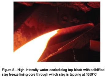
Slag-only tapping
With its high Pr number and elevated melting properties (Table I), slag - provided it is kept free of metal/matte/bullion - is potentially the simplest liquid for which to design an effective tap-hole system, comprising merely a high-intensity water-cooled copper slag tap-block protected by an accretion freeze lining of product slag. A significant advantage of slag-only tapping is that it facilitates direct downstream treatment of slag by either traditional water granulation (Atland and Grabietz, 2001; Szymkowski and Bultitude-Paull, 1992), or, increasingly, 'dry' air atomization (sometimes with energy recovery) to obtain useful slag products amenable to handling and sale in ironmaking, steelmaking, and Ni and SiMn ferroalloy applications (Andō, 1985; Rodd et al., 2010).
Dedication of the tap-hole to slag is particularly effective for handling corrosive slags (especially acidic slags >50% SiO2 that are fundamentally incompatible with basic and some other refractory oxides), because there is no chemical potential for reaction with a frozen slag of essentially the same composition. Thus retention of a protective freeze lining reverts to a more predictable issue of designing for thermal equilibrium thickness, and adoption of suitable safety factors to provide some protection against deviations therefrom.
On many industrial furnaces, a combination of level measurement and phase separation is more than adequate to tap slag free of metal/matte. Nishi (2007) reports on the importance of designing the height of the slag tap-hole to avoid Mn ferroalloy discharge through it. This is also a typical requirement of more quiescent EF or slag cleaning furnace (SCF) processes of low (< 20%) metal/matte fall (effectively 'slag-making' processes, that may even be subject to near-continuous slag tapping, such as Co and Ni ferroalloy and base metal and PGM matte smelting). On other matte flash furnace (FF) to TSL converting processes (e.g. blister Cu to PGM matte, respectively), it is typically necessary to equip them with downstream FF settling and/or SCF processes for further recovery of pay metals from slag, especially oxidic losses that require recovery through reductive processes.
Theoretically, the critical height for entrainment (he) of a two-layer liquid through an orifice of diameter (d) is related to αdFr0, where α depends on the density difference and which phase is being withdrawn (typically α< 0.625 when lower viscosity phase is withdrawn; α> 0.8 when uppermost viscous layer is withdrawn), Fr = v/(dgΔρ/ρ) and v is the discharge velocity, Δρ is the density difference between heavier and lighter liquid, and ρ is the density of the lighter liquid (Liow et al., 2001, 2003). Using assumed physicochemical properties and tap-hole conditions (Table I), one can predict heof the order of 0.12 m for copper FF settler and PGM EF smelting (and theoretically even ironmaking BF conditions). Not too surprisingly, therefore, the dedicated slag tap-holes located up to 1 m above the metal/matte tap-holes, coupled with tight metal/matte level control (to a maximum height of 0.25-0.4 m above matte tap-holes on blister Cu and PGM matte furnaces - Table I), permit slag tapping substantially free of metal/matte from the interface with the bulk slag, and entrained specifically through tapping (ignoring the presence by other sources of entrained and unsettled metal/matte droplets).
Similar two-phase liquid entrainment and an initial declination of the slag interface towards the tap-hole as tapping commences followed by a switch to initial inclination and even 'pumping' out of the tap-hole later in the tap has been modelled on BFs by CFD (Shao, 2013; Shao and Saxen, 2011, 2013a, 2013b). However, in the modelling of BF tapping, He and co-authors (2012) caution that the metal should not be maintained at a depth too low above the tap-hole, as one runs a risk of entraining process gas by 'viscous fingering' during tapping, especially (1) when the slag viscosity is high, or (2) in the presence of a permeable bed of solids through tapping occurs (e.g. coke bed).
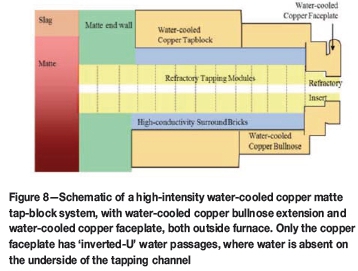
The efficacy of intense copper cooling (predominantly in a circular slag tap-block configuration) is clear (Figure 1 and Figure 2). These coolers directly impart a thicker protective freeze lining than the alternatives of just top lintel copper blocks, or 'inverted-U' square copper blocks and circular block water-cooled copper pin designs (Marx et al., 2005; Henning et al., 2010) (the latter choosing rather to try to moderate freeze lining thickness). These latter designs all avoid the presence of water below the tap-hole. It is a moot point whether this is indeed universally a safer situation, especially if control of furnace operating levels is adequate, simply because of the less desirable trade-off of imparting an inherently thinner protective freeze lining with less cooling.
Concerns frequently articulated of overly cooling copper coolers (Trapani et al., 2003; Marx et al., 2005; Henning et al., 2010) are extravagant costs, fear of preventing easy tap-hole opening, or freezing of a tapping stream. Even with the least intense top lintel or shallow-cooled (i.e. water circuits outside the furnace) copper and refractory-lined slag tap-blocks, problems associated with the latter two operational aspects can occur, and are generally coupled with undesirable increased copper slag tap-block wear rates. Szekely and DiNovo (1974), in a modelling study of the critical factors for tap-hole blockage of a molten stream (e.g. during tapping), determined that nozzle diameter was most critical, followed by metal superheat, with the extent of preheating (or in this case cooling) of the nozzle walls being less significant. Effectively, this implies that the tapping channel diameter should be enlarged if the slag tapping stream is freezing.
So again it is a moot point if reduced cooling intensity, including the removal of water circuits from beneath the tapping channel, indeed universally represents the safer option, if the consequent (sometimes inadequate) protective freeze lining thickness results in increased copper hot-face temperatures that will reduce the long-term integrity of the copper block itself (i.e. requires sustained temperatures below 461°C [Robertson and Kang, 1999]). Furthermore, if the tap-hole is still prone to 'slow tapping' even with less intense cooling, it may suggest that an alternative operational tapping strategy is appropriate.
Some of the larger ferroalloy furnaces for Mn and DC Cr alloy production also operate separate slag tap-holes, which assist greatly in separating post-tap-hole metal- and slag-handling logistics. In many instances the separate slag tap-holes are merely refractory graphite/microporous carbon/carbon tap-blocks (usually the former two owing to improved resistance to wetting and lower corrosion by slag). Increasingly, deep-cooled (i.e. water-cooled copper extending inside the furnace) copper lintel, or 'inverted-U' blocks are used to promote cooling of such refractory slag tap-holes.
Combined metal/matte and slag tapping
This is decidedly the norm, but it also often presents the greatest design challenge because of the different natures of slag and metal and their chemical incompatibility with linings selected as suitable for the other phase. Traditionally, refractory tap-blocks (refractory oxide or carbon-based) were adopted for combined metal/matte and slag tapping. With few exceptions, the refractory oxides are relatively resilient to metal- and matte-only tapping. Carbon-based tap-blocks risk carbon dissolution and/or oxidation (e.g. by dissolved oxygen) in service with carbon-unsaturated metal/matte. Corrosion of both carbon-based and oxide refractories is invariably accelerated by slag, even to the extent that corrosion becomes catastrophic, e.g. if acidic slags make contact with basic refractories (such as magnesia). Depending on the specific slag system, amphoteric (alumina) refractories can also be susceptible to both acidic (e.g. high-silica) or basic (e.g. high-lime) slags.
Refractory-lined overflow launders are used in continuous tapping of copper matte and slag from the Mitsubishi Continuous Process smelting furnace, and certain corrosion challenges are presented (addressed largely by fused cast magnesia-chrome). Somewhat remarkably, unlined water-cooled copper tap-plates are routinely fitted on to the furnace exterior for combined matte-slag tapping elsewhere in the copper industry, such as TSL furnaces. This presumably is only possible owing to the comparatively low temperature (< 1200°C, Table I) and relatively low copper matte superheat in combination, critically, with slag that has the potential to freeze (even if only as a thin layer a couple of millimetres thick) as a protective accretion on copper tapping surfaces.
Most combined metal-slag tap-hole processes are characterized by lower slag-metal ratios of about 0.4-1.5 t slag per ton metal (metal fall is approximately 35-60% in the case of Cr and Mn ferroalloys, Table I), or significantly lower 0.2-0.4 t slag per ton HM in ironmaking BFs (metal fall is approximately 65%, Table I), to near-slagless tapping in Si (and Si alloy) processes. A striking feature of the ironmaking BF is its sheer productivity (>10 000 t/day) coupled with complex internal process structures ('deadman' and tap-hole 'mushrooms'). Even with multiple tap-holes, these process structures would complicate attempts to control hot metal and slag levels adequately and to the extent necessary to permit effective dedicated metal- and slag-only tapping. Therefore, as with the majority of older ferroalloy SAFs and BFs, deep cooling is generally not contemplated, with limited water-cooled elements being applied more judiciously.
Dedicated metal/matte tapping
Provided that metal/matte can be tapped substantially slag-free, a configuration for dedicated metal/matte tapping is possible. Theoretically, it can be calculated that the separation of slag to at least 0.07 m above the metal/matte tap-hole should facilitate matte tapping without slag entrainment (α drops to 0.625 for tapping of the denser, less-viscous phase [Liow et al., 2003]). Efficient separation of metal/matte from slag already in the furnace decidedly simplifies post-tap-hole handling and associated logistics.
Emergency/drain tap-hole
Some furnaces are equipped with emergency/drain tap-holes (Newman and Weaver, 2002) that are used when the furnace does not drain from operating tap-holes (Cassini, 2001), or to effect bath drainage to a lower level than normal operating tap-holes for safer repairs. Some operators prefer to avoid such tap-holes for fear that they potentially increase risk by tempting non-emergency/non-drain use, and present another weakened region of furnace lining (at a higher pressure head) for unplanned drainage.
Tap-hole design
Tap-hole and tapping-channel heat transfer
On a large furnace crucible wall, bath heat transfer can reasonably be approximated as one-dimensional. In the simplest configuration of a long circular tap-hole, heat transfer from a fast-flowing hot tapped liquid is dominated by radial heat loss in the passage down the tapping channel. Even with a reasonably fast water cooling flow rate of 6 m3/h, it can readily be estimated using q = Q/A = (mCP) ΔT that for just a 1°C rise in water temperature, the equivalent tapping channel (tap-block or faceplate) heat flux (q) exceeds 0.5 MW/m2.
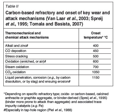
In a real tapping channel, in addition to the tapping channel heat transfer, heat transfer from the contained furnace bath also exists, which results in a three-dimensional heat transfer situation that is more extreme than in almost any other region of the furnace crucible. The tap-hole specifically is invariably subjected to the most arduous of conditions (Van Laar et al., 2003; Van Ikelen et al., 2000): the highest liquid (metal/matte and slag) velocities, affected by the degree of radial or peripheral flow and total flow that converge on the tap-hole to achieve the productivity set-point; the highest turbulence (increased by gas entrainment and even blowing under pressure, and associated enhanced mass and heat transfer from both stream tapping and through the action of any tap-hole clay flash devolatilization and subsequent 'boiling' at the back of the channel); wildly fluctuating and periodic thermal loads (from cool, dormant conditions, heating rapidly when the tap-hole is opened with oxygen, or hot liquid tapping, and with tap-hole clays 'boiling' and gas bubble-driven circulation upon tap-hole closure); and high dynamic loads (the action of opening and closing a tap-hole). Tap-holes are also prone to gas leakage, especially when operated under pressure in a BF, which may result (particularly in the case of ironmaking or ferroalloy processes adopting carbon-based refractories) in a continuous threat of exposure to, and reaction by, CO (the risk of carbon deposition), oxidation by injected oxygen, air, or steam (especially if water leaks), slag and maybe even SiO(g), and reaction with volatile gas species such as alkalis and zinc (which leads to refractory attack) (Van Laar, 2001; Van Laar et al., 2003; Spreij et al., 1995; Iiyama et al., 1998; Tomala and Basista, 2007).
Tap-hole 'refractory' design
Clearly, to be successful, tap-hole designs need to cater not only for average, but peak, process heat flux conditions. Van Laar (2014) suggests that in BF tap-holes, peak heat fluxes exceeding 1 MW/m2 have been detected, which is considerably in excess of the normal average heat fluxes measured (25 kW/m2, Table I). This would not be inconsistent with a 1.4 MW/m2 event involving metal encroaching on the lower zone of a copper waffle cooler recorded in Co ferroalloy production (Nelson et al., 2004).
Nearly all tap-holes are designed with a length that exceeds the adjacent sidewall thickness. Unfortunately, this provides only short-term protection against liquid breakout in the tap-hole area, because the tap-hole length will at best rapidly recede to its thermal equilibrium dimension.
Several refractory types (Figure 3) are used in BF tapholes and their environs (Stokman et al., 2004; Jameson et al., 1999; Irons, 2001; Van Laar, 2001; Van Laar et al., 2003; Brunnbauer et al., 2001; Atland and Grabietz, 2001). They include:
► 100% alumina (the most 'insulating': k = 1-5 W/m°C)
► Pitch-impregnated carbon/alumina (Black and Bobek, 2001)
► Large carbon blocks (k approx. 14 W/m°C)
► Hot-pressed small carbon or semi-graphite bricks (a lower iron content of the latter, to reduce CO disintegration [Stokman et al., 2004; Spreij et al., 1995])
► Microporous (potential advantages of less metal infiltration if the maximum pore size is less than 1 μm [Stokman et al., 2004; Piel et al., 1998; Spreij et al., 1995; Tomala and Basista, 2007]), large carbon or semi-graphite blocks
► Thermally conductive graphite (k approx. 140 W/m°C, frequently applied as 'safety' tiles glued to the steel wall in the immediate tap-block vicinity [Van Laar et al., 2003; Edwards and Hutchinson, 2001; Atland and Grabietz, 2001])
► Sometimes graphite with high-alumina silicon carbide castable in the centre (favoured for reasons of improved tapping stream dissolution and erosion resistance over graphite in the event of the latter's loss of freeze lining or protective baked tap-hole clay inner annulus, somewhat improved tolerance to oxygen lancing over graphite, provision of some heat storage for tap-hole clay baking, and possibly some improved tolerance to microcracking induced through mudgun and drill impact forces)
► The use of higher conductivity silicon carbide (Brown and Steele, 1988) in conjunction with a carbon surround and alumina tapping channel hot-face bricks has also been reported (Yamashita et al., 1995). In some instances, heat removal is further enhanced by the addition of water-cooled iron or copper tap-hole notch channels, or even water-cooled copper inserts/plate coolers (Irons, 2001; Van Laar, 2001).
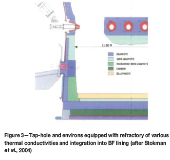
In all instances involving the use of composite refractory types (Figure 3), especially when water-cooled components are included, a critical design requirement is to cater for differential thermal expansion properties that can easily differ by an order of magnitude, with the potential to cause gaps, stresses, and strains, so raising the potential for liquid infiltration (Van Laar, 2014). An experience reported (Duncanson and Sylven, 2011) of furnace campaign life reduced from 14 to just 3 years when switching from a design where 'the original furnace had forced air cooling in the bottom, but no additional (water) cooling for the furnace walls' (and, by inference, attempt at freeze lining in, or at least near, the tap-block) may well illustrate this. Moreover, the additional requirement for effective freeze linings around thermal equilibrium has led Singh and co-authors (2007) to state: 'but in the present Indian scenario with process parameters not stable ... it is difficult to maintain the conditions inside the furnace desirable for a true freeze lining,' so failing to 'give the expected lifetime of over 25 years'.
For the adoption of any freeze lining concept, half measures are entirely unacceptable. The achievement of just a partial and/or periodic freeze lining will prove unsuccessful and present a considerably more dangerous operating condition than a traditional insulating tap-hole design concept.
The first technique crucial to tap-hole refractory longevity is the ability to create and retain a protective accretion freeze lining or skull (Eden et al., 2001), as tap-hole performance is greatly compromised by operating in the partial or substantial absence of a stable accretion freeze- lining, which is described as a 'no-skull' condition (Stokman et al., 2004). Accretion freeze lining thickness has already been shown to be enhanced by placing refractories of higher conductivity in actively cooled furnace-lining systems, with the resulting colder refractory presenting fundamentally more resistance to attack by a number of wear mechanisms, depending on the temperature of onset of thermomechanical or chemical attack by a given mechanism (Table II).
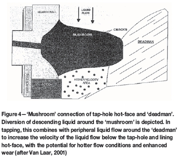
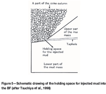
Role of the tap-hole clay 'mushroom'
The second crucial feature, specific to ironmaking BF tap-hole design, is the active development and continuous renewal of a tap-hole clay (also described as mud) 'mushroom' to provide some hot-face protection on the back of the tapping channel (Figure 4) (Uenaka et al., 1989; Jameson et al., 1999; Eden et al., 2001; Nightingale et al., 2001, 2006; Tanzil et al., 2001; Atland and Grabietz, 2001; Cassini, 2001; Wells, 2002; Horita and Hara, 2005; Kageyama et al., 2005, 2007; Nakamura et al., 2007; Niiya et al., 2012; Kitamura, 2014). The 'mushroom' requires tap-hole clay for its development and consists additionally of incorporated slag, iron, and coke. Tsuchiya and co-workers (1998) hypothesize that a necessary condition for the development of a 'mushroom' is that the tap-hole length can be extended only when the holding space for the injected tap-hole clay is effectively realized, so that the major part of the tap-hole clay surface is covered by the coke column (Figure 5). Niiya and co-authors (2012) hypothesized further that the tap-hole clay is 'extruded in the furnace like strings' and that these 'strings accumulate in the coke-free spaces by folding together with solidified iron and/or slag'. Other conditions required for increasing the tap-hole length to develop the 'mushroom' then include there being sufficient tap-hole clay sintering time in the holding space and the specific characteristics of the clay during and after heating and sintering. 'Mushroom' stability can be adversely affected by the 'floating' of an ironmaking BF 'deadman', especially if it is physically connected to the back of the 'mushroom' (Van Laar, 2001). Water leaks are also reported to cause a 'mushroom', a frozen skull, and lining damage (Van Laar et al., 2003; Van Laar, 2001).
The necessary condition of a 'holding space covered by a coke column' may well explain why a protective tap-hole clay 'mushroom' is routinely reported only for ironmaking BFs. In non-ferrous processing coke is absent (or substantially absent), so the necessary requirement of a coke column to cover tap-hole clay in the holding space is missing. Moreover, as we describe later, certainly in electric smelting of PGM mattes, matte superheat is so high (as much as 650°C, Table I) that tap-hole clay injected into matte appears to react near-instantaneously, with the release of gas and extreme turbulence, so that a tap-hole clay-based 'mushroom' cannot be stabilized.
While a coke bed is a well-reported feature of ferroalloy smelting (Nelson, 2014), it remains local to the electrode tips. The extension of the coke bed to the furnace tap-hole - a necessary condition of the proposed mechanism of 'mushroom' development - would almost certainly result in a condition too conductive for effective electrical power input. A genuine 'mushroom', at least in the equivalent sense to that of an ironmaking BF, therefore seems improbable. At best, some extent of tap-hole clay 'self-lining', but not a 'mushroom', is depicted in ferroalloy electric SAFs (Ishitobi et al., 2010).
Ferroalloy tap-hole design
The ironmaking BF tap-hole refractory list fairly represents the experience in Cr, Mn, and Si ferroalloys, one of an increasing general trend towards the use of materials of higher thermal conductivity, and to what is colloquially known in the industry as 'freeze linings'. For traditional insulating (especially large) furnace designs, just 2-6 years of furnace lining life on Cr and Mn ferroalloys are commonly reported (De Kievit et al., 2004; Van der Walt, 1986; Coetzee and Sylven, 2010; Coetzee et al., 2010), with one slag tap-hole life reported to be as short as 2 months (Van der Walt, 1986). However, longer furnace lifetimes of 10-15 year have been achieved on traditional insulating linings in Japan. Generally, Cr and Mn ferroalloy SAFs have made use of only refractory alumina tap-blocks, silicon carbide tap-blocks surrounded by alumina, carbon, or microporous carbon blocks.
This supports a progression from more insulating refractories (refractory oxide castable and brick, carbon-based ram or SÖderberg paste), to carbon blocks of intermediate thermal conductivity and even more thermally conductive semi-graphites and graphites. The latter designs have delivered in excess of 20 years' lining life on some large Mn ferroalloys furnaces (Van der Walt, 1986; Hearn et al., 1998).
An emerging trend is of an additional composite refractory variant involving use of a thermally conductive graphite sleeve inside an insulating carbon tap-block (Figure 6). This concept, intriguingly, is the converse of placing insulating refractory oxide inside graphite, reported as a preferred option for ironmaking BFs.

Hearn and co-workers (1998) describe the reasons for this as follows: the end hot-face of the graphite insert is protected by a carbon tap-block, while the cold-face is protected by a removable carbon 'mickey' block, which can be replaced if damaged by either drilling or oxygen lancing, to secure a flat mating surface against which the mudgun can more effectively close without excessive tap-hole clay bypass. During tapping the graphite absorbs the tap heat, which the outer annulus carbon tap-block of lower thermal conductivity cannot transmit as effectively, so ensuring a hot tap-hole with improved flow rates. The heat retained in the graphite sleeve after tapping and immediately following tap-hole closure by the mudgun aids tap-hole clay baking. At the next tap, a 45 mm diameter hole is drilled through the baked taphole clay core to create a tap-hole clay annulus inside the graphite sleeve that affords some protection against its coming into direct contact with the molten tap stream. Obviously, the tap-hole clay can erode with time. With the removal of the front 'mickey' carbon block, the graphite sleeve can be core-drilled out and both items replaced to effect a taphole repair. An additional tap-hole repair design feature involves splitting in two and gluing the carbon tap-block (which contains the graphite sleeve) with carbon paste rammed to close the gap between it and the adjacent furnace sidewall lining, a measure that allows for easier removal with less peripheral lining damage during replacement in planned maintenance (Duncanson and Sylven, 2011; Coetzee and Sylven, 2010; Coetzee et al., 2010).
Some Mn (Ishitobi et al., 2010) and DC arc Cr (Sager et al., 2010) ferroalloy furnaces make use of inserted water-cooled copper components on both metal and slag tap-blocks, components that range from top lintel to 'inverted-U' designs, to cool the graphite (advantage of less wetting by slag) or microporous carbon (if dissolution and erosion of graphite by the metal tapping stream prove too aggressive) tap-blocks.
High-intensity water-cooled tap-block design
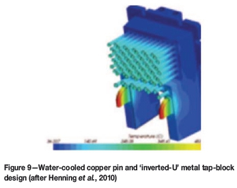
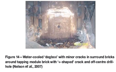
Quite different, though, are the more intensely cooled tap-block designs on blister Cu (Henning et al., 2011; Marx et al., 2005; George-Kennedy et al., 2005; George, 2002; Zhou and Sun 2013; Newman and Weaver, 2002; pers. comm. 1999, 2003) and non-autogenous processes requiring electric smelting, such as Ni and Co ferroalloy (Henning et al., 2010; Nelson et al., 2004, 2007; Walker et al., 2009; And, 1985; Voermann et al., 2010; pers. comm. 1999, 2003), base metal, and PGM matte furnaces (Cameron et al., 1995; Shaw et al., 2012; Hundermark et al., 2014; Nolet, 2014; pers. comm. 1999, 2003, 2010). These almost universally adopt water-cooled copper tap-blocks of rectangular shape: three-sided (inverted U-shape, so there is no water-cooled copper below the tapping channel), four-sided 'dogbox' (Figure 14; Nelson et al., 2007), or high-intensity one-piece waffle cooler copper tap-block designs (Figure 7 and Figure 8). Some are equipped with pin cooling (with inverted-U water passages [Henning et al., 2010]-Figure 9).
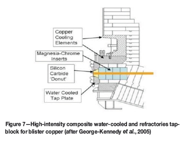
These copper coolers are lined internally with a square configuration of surround bricks, usually made of magnesia (graphite was apparently also trialed successfully in nickel matte smelting [Cameron et al., 1995], but was reported to have been discontinued), containing internal tapping module refractory bricks through which the tapping channel runs (Figure 7, Figure 8, Figure 12 and Figure 14). The latter comprises refractories that vary with commodity: almost exclusively pitch-impregnated magnesia in Ni ferroalloys (Nelson et al., 2007; pers. comm. 1999, 2003), magnesia-chrome in blister Cu or matte (Cameron et al., 1995; Nolet, 2014; George- Kennedy et al., 2005; pers. comm. 1999, 2003), or alumina-chrome in PGM mattes (Nolet, 2014; pers. comm. 1999, 2003). Both graphite and silicon carbide have been trialed in matte smelting (Cameron et al., 1995; pers. comm. 1999, 2003).
For Pb bullion (temperatures of 800-1100°C tapping, with 700°C drossing) (Veenstra et al., 1997; pers. comm. 1999, 2003) and PGM matte processes (Shaw et al., 2012; Hundermark et al., 2014; Nolet, 2014; pers. comm. 1999, 2003), process superheats are high (Table I). Specifically for the latter, process temperatures are elevated to the extent that the potential for corrosion of magnesia chrome refractory by PGM matte above 1500°C has recently been investigated (Lange et al., 2014). Good evidence of expected significant matte penetration and signs of FeO and MgO corrosion products have been found, but not as yet a CrS product suggested by any proposed mechanism. This suggests a potential for high refractory wear rates with exceptionally high matte superheats (approaching 650°C, Table I).
In Pb bullion smelting (Veenstra et al., 1997; pers. comm. 1999, 2003), blister copper (Henning et al., 2011; pers. comm. 1999), and PGM matte ACP top submerged-lance converting (Nelson et al., 2006; pers. comm. 2003), circular copper tap-blocks have also been used, with both annular graphite and silicon carbide inserts, or silicon carbide, high alumina, or graphite tapping module bricks.
So whereas ironmaking BF superheats of 350°C may seem challenging to copper-cooled operations, they are only half the matte superheats experienced on the highest intensity non-ferrous operations. Consider also the significantly lower melting temperatures of many mattes (<950°C, Table I) and this effectively makes it impossible to develop any protective matte freeze lining, even when using higher cooling water flow rates (but still short of those legislated for designation as pressure vessels). Notwithstanding this limitation, Ni and PGM mattes also have a greater solubility for copper than do iron and steel, blister copper, and copper mattes; so additionally they have a greater driving force for the chemical dissolution, not merely melting, of copper.
As we have described earlier, in such a harsh pyrometallurgical processing environment the consequence of a superheated matte/blister Cu 'hit', or lancing a water-cooled tap-block (George-Kennedy et al., 2005) and tap-hole failure is extreme. It can occur rapidly with a near-identical sequence of events, regardless of furnace size (Nelson et al., 2006). The potential for catastrophic cooler failure and/or furnace refractory breakout (Zhou and Sun, 2013; Newman and Weaver, 2002) within, most commonly, a few minutes of mudgun closure, is high (Hundermark et al., 2014). A breakout following mudgun closure has even prompted one PGM producer to resort to drilling and lancing, but to closing tap-holes with clay manually using stopper rods rather than mudguns (Coetzee, 2006).
Faceplate and refractory insert design
External faceplates are important for providing a 'perfectly' flat vertical mating face for the mudgun to engage the tapping channel (for accuracy of tap-hole clay quantity injected into the tapping channel, so ensuring minimal bypass), coupled with the refractory insert, for providing a mechanism to help secure tight joints along the length of the tapping channel to minimize infiltration and gas leakage (Eden et al., 2001), and to help prevent the entire tapping channel lining from dislodging and 'tapping' out of the furnace lining owing to internal furnace pressure (comprising both internal operating pressure and any blast pressure and hydrostatic head). The last of these incidents has apparently been experienced in the past on a Ni matte EF.
Thermal fatigue cracking or direct matte attack of water-cooled copper faceplates, typically associated with matte splashing during tap-hole plugging, presents a risk of water leaks. Sacrificial refractory or metallic cover plates have been used to address this risk (Cameron et al., 1995), with the introduction of inverted-U water-cooled pipe arrangements to secure the absence of water-cooling directly below the tapping channel, a measure that better mitigates the risk of matte making contact with water.
Tap-hole inclination and active hearth sump design
Tap-holes are normally designed with a horizontal or vertical ( e.g. EBT) orientation. The notable exception is the near-universal implementation of inclined tap-holes (approx. 10°) on ironmaking BFs. Modelling has shown that inclined tap-holes, coupled with longer tapping channels and deeper hearth sumps (the minimum sump depth is 20% of the hearth diameter [Jameson et al., 1999; Gudenau et al., 1988]) that drain liquid deeper in the furnace (further from the sidewalls), lower liquid velocities (and resultant wall shear stress and wear) both below the tap-hole and at the wall periphery (that otherwise lead to undercutting and so-called 'elephant's foot' wear) (Stokman et al., 2004; Eden et al., 2001; Smith et al., 2005; Dash et al., 2004; Jameson et al., 1999; Post et al., 2003). The localized higher velocities below the tap-hole are attributed to the draining of liquid down past the 'mushroom' (Figure 4, Van Laar, 2001). The higher peripheral velocities at the wall periphery are more a function of draining through and around a 'deadman' (Dash et al., 2004; Jameson et al., 1999; Tanzil et al., 2001). Optimum tap-hole inclination was modelled as 15° (Dash et al., 2004). Tapping conditions are further noted to distort fluid flow to the extent that, towards the end of tapping, the slag is lowest in the vicinity of the draining tap-hole, inclined to its highest at the opposite side of the BF (Post et al., 2003; Tanzil et al., 2001). We are aware of at least one high-carbon (HC) Cr ferroalloy furnace equipped with a declined tap-hole.
Modelling has similarly motivated the deepening of the metal bath of a circular HC Mn ferroalloy SAF (but still with a horizontal tapping channel, presumably in part because of the absence of anything equivalent to a 'sitting deadman') by removing a full course of carbon blocks to reduce the peripheral liquid flow velocity along the wall to a draining tap-hole (Ishitobi et al., 2010). The reduced peripheral flow induced by the deepening of the hearth reduced metal tapping temperatures by an average of 40°C (to 1350°C), despite the uprating of the transformer capacity to permit a simultaneous increase of the electrode current by 25 kA to raise the average power load at night by 2.3 MW, combined with operation at a higher coke loading to allow approach to metal carbon saturation (so limiting wear by dissolution of the carbon lining). Deepening of another Japanese HC Mn ferroalloy furnace gave benefits of marginally increased power input, faster tapping, and increased productivity (Nishi, 2007). On Si ferroalloy SAFs (Kadkhodabeigi et al., 2011), where metal drains through a porous bed of solids to the tap-hole, crater pressure and bed permeability significantly influence the rate of drainage of metals to and through the tap-hole.
In the largest rectangular six-in-line PGM matte smelting furnace, the matte inventory can exceed 600 t, with contained metal value exceeding US$50 million. Furnace deepening will come at a greater cost. Fortunately, with a combination of periodic and low-volume matte tapping (< 20% matte fall) through an end-wall of an inverted arch hearth design, in a rectangular furnace configuration, tap-hole wear has recently been predictable even at operations exceeding 60 MW power input (Hundermark et al., 2014). With a circular furnace configuration more conducive to the development of circumferential flow along the sidewall to a draining matte tap-hole, especially when the matte tap-hole is located almost on the top of the skew line of the hearth invert, it is not inconceivable that conditions for accelerated matte tap-hole wear could develop, even at far lower inputs of power.
Tap sequencing
A variety of strategies are adopted, depending largely on productivity requirements, number and layout of tap-holes, and process conditions. For single tap-holes processing dual metal-slag mixtures, total reliance is placed on the availability of the sole tap-hole. Such tapping systems are especially common in Cr and Mn ferroalloy SAFs, which may emphasize the importance of the tapping stream superheat (average-to-maximum heat flux 1-10 kW/m2 [De Kievit et al., 2004; Table I]) over absolute temperature in describing an onerous process condition.
That said, a still impressive 5 700 t/d HM in a campaign life of 13 years at the time of reporting was achieved from a single taphole BF operation (Ballewski et al., 2001). Similarly the Mitsubishi Continuous Process for copper relies on continuous liquid flow down heated launders from smelting, to slag cleaning, to converting, and to anode refining furnaces, this being effected through a combination of furnace overflow, skimming, and siphon tapping arrangements, at overall availabilities exceeding 92% (Matsutani, n.d.). These examples illustrate what is possible with superior tap-hole management and tapping practices.
Consecutive individual tapping practice
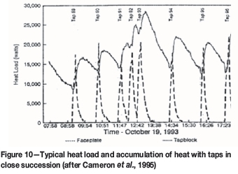
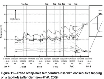
Consecutive tapping on an individual tap-hole is a common traditional practice on several ironmaking BFs (Rüther, 1988; Cassini, 2001), ferroalloy, and matte-smelting operations. Even on two-tap-hole BFs, tapping campaigns of 4 days to 3 weeks are reported (Rüther, 1988). Matte tap-hole temperature trends in Ni matte smelting clearly demonstrate the accumulation of heat in the tap-hole refractory when taps are in close succession (Cameron et al., 1995; Figure 10). Similar rising temperature trends with tapping have been observed in PGM matte smelting (Gerritsen et al., 2009; Figure 11). With an ironmaking BF interpretation this could possibly be considered desirable for promoting tap-hole clay baking and sintering. However, in the more intensely superheated matte-only tap-hole environment this is rather interpreted to imply that a resting or recovery period of no tapping is called for, to help lower refractory temperatures and re-establish improved accretion, as evidently occurred on the tap-hole on the furnace in Figure 10.
Alternating tap-hole practice
This variant, also described as 'side-to-side' casting (Petruccelli et al., 2003), is certainly the norm for achieving the highest of productivities through optimal tap-hole condition, consistent operability, and reliable availabilities; it also best supports preventative tap-hole maintenance. This is true of two tap-holes (Petruccelli et al., 2003) and tap-hole pairs on four-tap-hole ironmaking BFs (Rüther, 1988; Steigauf and Storm, 2001); 2-8 metal-only and 2-6 slag-only tap-holes on blister Cu and ferroalloy furnaces (George, 2002; Zhou and Sun, 2003; Newman and Weaver, 2002; George- Kennedy et al., 2005; Nelson et al., 2004, 2007; Walker et al., 2009; pers. comm. 1999, 2003); and up to three matte- and three slag-only tap-holes on base metal and PGM matte EFs (Nolet, 2014; Nelson et al., 2006; pers. comm. 1999, 2003). It includes ironmaking BF variants described as 'back-to-back' or 'mother-daughter' tapping (Irons, 2001; Cassini, 2001), where a pair of taps is made before alternating tap-holes. In the case of the ironmaking BF, this practice of a pair of taps is usually in response to suboptimal conditions, such as inadequate draining or persistent taps of short duration.
A detrimental feature reported for alternating tapping on BFs, where a zone of low permeability exists between tap-holes, is the potential for the slag level to rise due to excessive pressure loss, which disrupts bosh gas flow (Iida et al., 2009; Shao, 2013; Shao and Saxen, 2011, 2013a, 2013b). Slag levels could conceivably fluctuate on SAFs similarly, owing to the presence of less permeable zones. Iida and co-workers (2009) recommend enlarging the tap-hole diameter (by approx. 10%) as the best remedy to alleviating this issue.
While operating at a still impressive HM superheat, ΔT approx. 350°C, the focus on the BF is largely HM productivity-driven, with up to 75% metal fall and daily targets exceeding 10 000 t HM, thus demanding the most effective and efficient tapping with reliable operability. Most operators appear to seek to operate somewhere close to a 'dry' hearth condition (De Pagter and Molenaar, 2001), in which hot metal and slag levels in the hearth are kept as low as possible (Van Laar et al., 2003), but without escape of hot gas (Nightingale et al., 2001; Tanzil et al., 2001). In contrast, the requirement on the multiple tap-hole, lower metal/matte fall (<20%) Ni ferroalloy and matte furnaces is primarily to secure maximum tap-hole and furnace reliability. This is especially true of high-intensity PGM matte furnaces, with their onerous matte superheat, ΔT approx. 650°C, that imposes integrity challenges on even the most intensely water-cooled, refractory-lined copper tap-hole.
On the highest intensity of these operations, even with less frequent matte tapping events, the practice generally is to alternate tapping between the available tap-holes in order to give the tap-holes maximum 'recovery' time to lower tap-hole temperatures between taps. This is reported (Eden et al., 2001; Mitsui et al., 1988; Entwistle, 2001; Cameron et al., 1995; Gerritsen et al., 2009) and has been modelled in the BF (Ko et al., 2008). The merits of such an approach, originally diagnosed from scrutinizing well-instrumented copper tap-block and cooling water temperature tapping trends, are presented using the latest fibre-optic temperature measurement trends available in PGM matte smelting (see section on Advanced tap-hole monitoring).
At first glance an alternating tap-hole practice would appear to complicate the timing of minor routine, monthly planned tap-hole maintenance activities (Nolet, 2014). However, it should be appreciated that, despite such diligent monthly repairs and essentially slag-free tapping, process conditions remain so onerous that all but the hot-face matte tapping module bricks have to be replaced roughly every quarter to secure incident-free tapping, good tap-hole condition, and ultimately furnace integrity and longevity. To undertake such a deep tap-hole repair, tap-hole temperatures and safety dictate that the furnace power needs to be lowered for the duration of the repair. So in fact a simultaneous repair of all matte tap-holes by a team of masons on a furnace at lowered furnace power actually minimizes the impact on overall furnace utilization.
Also, it should be clarified that in high-intensity PGM matte smelting the 'as-low-as-possible' liquid matte and slag levels of the BF 'dry hearth' operation are definitely not sought, nor considered desirable. Considering first the overall liquid level, one finds that generally too high a pressure head is not sought, because it promotes an increased rate of tapping and increases the potential for matte infiltration of the furnace lining. Specifically, one also does not seek too high a matte level, for fear of exposing the effective slag-line, water-cooled copper waffle coolers to a greater risk of making contact with superheated matte. While the waffle cooler design reportedly (Trapani et al., 2002; Merry et al., 2000) caters for metal contact of copper waffle coolers in Ni (Nelson et al., 2007) and Co (Nelson et al., 2004) ferroalloy processing, contact by matte, especially superheated matte, can rapidly lead to catastrophic failure.
However, this still does not warrant seeking the lowest possible matte level. This is because the matte-only tap-hole is especially configured to be refractory oxide-lined, with generally good corrosion resistance to matte, but with decidedly poor corrosion resistance to acidic slags (> 50% SiO2 content). Indiscriminate lowering of the matte level would therefore not only expose the tap-hole to the risk of 'slagging' by the hotter slag, but would accelerate corrosion, and ultimately wear, of the refractory lining. A target minimum matte level is therefore simultaneously sought with matte operated below the maximum matte level permissible.
In respect of the slag level, the absolute minimum furnace slag level is controlled by its interface with matte. Operation around the slag tap-hole, located typically approximately 1 m above the matte tap-hole (Table I), represents the lowest overall pressure head condition on the matte, which is beneficial. However, at the highest smelting rates with < 20% matte fall, slag make becomes significant, which requires near-continuous tapping in contrast to periodic batch matte tapping. With the slag level only at the level of the slag tap-hole, the pressure head is simply inadequate for slag tapping rates to be acceptable. So a practical minimum operating slag level exists, above which slag tapping rates are adequate for achieving an efficient rate of slag drainage (even if multiple slag tap-holes are open).
Finally, the maximum permissible top of slag level is designed relative to the slag tap-hole. This measure primarily ensures that superheated slag does not rise above the zone of sound crucible containment below the top of the copper coolers, but also limits excess pressure head at both the slag tap-hole and the underlying matte tap-hole.
Slag tapping
Where consecutive tapping practice has indeed found nonferrous application is during 'slow' slag tapping on both Ni ferroalloy and PGM matte smelters. The slag tap-hole has a tendency to open fast and then the tapping rate declines with time. In situations where the number of slag tap-holes available is limited (e.g. owing to planned maintenance), an effective solution involves closing on lazy-flowing slag with the mudgun, and shortly thereafter re-drilling the slag tap-hole open again (exposure of drill bits to slag only is far less aggressive than exposure to metal or matte). This can easily double the initial tapping rate on a 'slow' slag tap-hole.
Closure on flowing slag is crucial to this operation, because it ensures easy re-drilling of tap-hole clay only to open the slag-tapping channel. In the event where the flow from a slag tap-hole has been allowed to stop, even with an attempted mudgun closure, an adequate plug of tap-hole clay to the inner hot-face cannot be secured. When re-drilling is attempted, solidified slag is quickly encountered, which impedes the drill and can cause skew drilling - potentially towards a water-cooled copper cooler! So somewhat paradoxically, to be safer, oxygen lancing with its ability to 'cut' open, and so straighten, the solidified slag tapping channel then becomes necessary to re-open the slag tap-hole.
Tap-hole opening
It is essential to be able to 'quickly and certainly open the tap-hole whenever required' (Tanzil et al., 2001).
Discounting the most primitive past practices of 'pricking' or 'excavating' the tap-hole open, a wide range of tap-hole opening methods are adopted (Ballewski et al., 2001), including:
► Manual oxygen lancing, suggested near universally to be minimized to < 1% of taps (Jameson et al., 1999), or for 'emergency only' on ironmaking BFs (Ballewski et al., 2001). This practice has led directly to a reported blister tap-hole failure and resulting explosion on at least one site (George-Kennedy et al., 2005), and yet is still adopted as the primary means of tap-hole opening on 36% of PGM matte furnaces (Nolet, 2014)
► Automated or robotic oxygen lancing (pers. comm., 2010)4
► A soaking bar technique5
► Conventional pneumatic drilling (air)
► Improved pneumatic drilling (nitrogen and/or watermist-bit cooling)
► Hydraulic drilling (nitrogen and/or water-mist-bit cooling)
► Combination pneumatic drilling (without opening) and deliberate lancing of the last remaining metal/matte plug.
It is worth noting that to avoid contamination by iron or other elements, metallurgical-grade silicon tapping requires a variety of alternative tools to open a tap-hole and maintain the flow of metal. These alternatives include an electric stinger (connected to a busbar system from the furnace transformers), a kiln gun (Guthrie, 1992)6, steel and graphite lances, wooden poles, and graphite bott tools (Szymkowski and Bultitude-Paull, 1992).
Tapping rate
A primary requirement of tapping is to reliably secure the desired rate of furnace products. Thus, it is important to establish the factors influencing tapping rate. Guthrie (1992), applying Bernoulli's equation, provides a useful estimate of tapping rate,  through a tap-hole of diameter d, where, CDis a discharge coefficient (approx. 0.9), g is the gravitational acceleration constant, and H is the effective liquid head of the phase being tapped, with a phase of density p.
Mitsui and co-workers (1988), combining Bernoulli's and Darcy- Weisbach's equations, estimated the iron BF tapping rates as  , thereby including a correction for the tapping-channel length (l). This yields typical iron BF tapping rates of 7 t/min (approx. 10 000 t/day on a near-continuous tapping basis) and liquid tapping velocities of 5 m/s in tap-holes of 70 mm diameter by 3.5 m length. Both approaches show that tap-hole geometry strongly influences tapping rate (with velocities of up to 8 m/s recorded [He et al., 2001; Atland and Grabietz, 2001]), primarily through the tap-hole diameter. The second equation suggests tap-hole length as the next most significant influence.
In the case of Si ferroalloy SAFs (Kadkhodabeigi et al., 2011), where metal must drain through a permeable bed of solids to the tap-hole, the height of liquid metal influences the onset of gas breakthrough to the tap-hole and the concomitant sudden drop in tapping rate, but exerts less influence than crater pressure and bed permeability on the initial tapping flow rate.
Tap-hole wear mechanisms
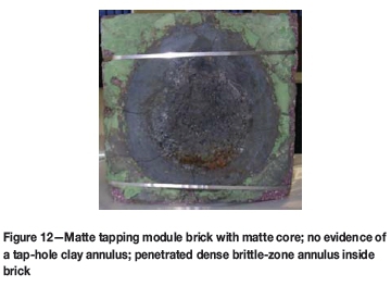
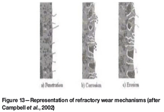
Given a dominant influence of tap-hole dimensions on tapping rate, it is instructive to consider factors contributing to tap-hole wear (Figure 12), which are elegantly summarized by three sequential steps: penetration, corrosion, and erosion (Figure 13; Campbell et al., 2002).
The first step in refractory wear involves the penetration of refractory, the rate of which, upen, can be described by a capillary-force-driven flow according to rγcose/4μlp, where r is the capillary (pore) radius, γ is surface tension, θ is the contact angle, lpis penetration depth, and μ is liquid viscosity. The last property (viscosity) is related inversely to process temperature.
Once a liquid has penetrated a refractory, corrosion by the infiltrating liquid becomes possible. Campbell and co-workers (2002) describe corrosion as a 'cooking time' to illustrate that its rate relates to how long a penetrated refractory has been at a temperature that supports reaction. Furthermore, as corrosion rate conforms to Arrhenius's Law, an exponential (as opposed to linear) scale of temperature is required to predict the increase in the rate of corrosion with temperature.
Once a refractory has been penetrated and further weakened by corrosion, erosion becomes possible if the shear stress, τ = μ(dv/dy) induced by the liquid flow through the tap-hole is sufficient to remove refractory. Once again, temperature affects liquid viscosity, whereas the rate of tapping affects the velocity gradient (dv/dy). Estimated tapping velocities of 1-5 m/s suggest that the applied shear force is a few orders of magnitude lower than the hot modulus of rupture of most refractories. So it is well-argued that tap-hole refractory erosion cannot occur until the refractory structure has somehow first been weakened by liquid penetration and corrosion (Campbell et al., 2002).
In PGM matte tap-holes an annulus of tap-hole clay does not appear to persist in lining the tapping module refractories (Figure 12). However, the same (low) velocities may possibly provide a shear force that is in excess of the hot modulus of rupture of poorly baked/sintered tap-hole clay. So in operations that critically depend on a 'maintainable' baked and sintered annulus of tap-hole clay to line the tapping channel to protect the tap-hole refractory (e.g. especially when combined tapping of more corrosive slag, as in ironmaking BFs), far more attention should be paid to the issue of tap-hole clay sintering and erosion-resistance properties (Mitsui et al., 1988).
Generally, the potential adverse influences of suboptimal tapping velocities are:
► Too slow tapping-limits tapped production; delays liquid drainage, which may potentially be unsafe if critical furnace levels are threatened (e.g. matte encroachment to near the vicinity of copper coolers, or slag overflow over the design maximum crucible containment height)
► Too fast tapping-induces loss of control, thereby creating unsafe tapping and post-tap-hole conditions; in the extreme, and only then, promotes tapping channel and furnace lining erosion.
These influences may have more adverse consequences than erosion does.
Drilling practices
Owing to the potential for oxygen-induced lancing damage to tap-holes, the vast majority of operations seek to practise drilling the tap-hole open. This typically includes sacrificing the drill bit and, potentially, the drill rod. In at least one Japanese Mn ferroalloy operation, to conserve costly drill bits, the operator withdraws the drill as soon as metal is expected to be encountered, places a sacrificial crimped steel pipe over the drill bit, and then drills the hole open. This protects the drill bit enough to permit re-use.
Combination drilling and 'plug' oxygen lancing practice
On most alloy-only and matte-only tap-holes operated in the substantial absence of any tap-hole hot-face 'mushroom', a combination of deep drilling followed by 'plug' oxygen lancing is practised deliberately. The aim is to drill through the tap-hole clay as (consistently) deep as possible (700-1200 mm, depending on tap-hole design length), until the drill encounters resistance from a 'plug' of metal/matte/ residual entrained slag. Experience indicates that attempts to drill further through this 'plug' often lead to unintended skew drilling. This measure is particularly hazardous in a water-cooled copper tap-block configuration, and often results in the drill simply getting stuck in the tapping channel. Even with reverse percussion hammering (Bell et al., 2004), it may become impossible to free a stuck drill bit and rod, an outcome that requires the tapper to resort to oxygen lancing to remove the obstruction.
In combination practice, the drill is then withdrawn, and the drill length measured accurately (but manually) with a gradated drill-T, which simultaneously verifies that the drilling was not off-centre. Once the drill-hole is confirmed as being straight, oxygen lancing of the short remaining tapping channel 'plug' is then undertaken to open the tap-hole. This usually requires a minimum of lancing (less than one lance pipe). In this way there is also a lower risk of tappers losing the skill of using oxygen lances safely owing to infrequent practice.
The rationale behind this practice is driven by a decided requirement not to overfill tap-hole clay, through the addition of a metered amount of tap-hole clay, which permits operation with a consistent short (as possible) tapping-channel 'plug' to lance.
Tap-hole drilling requirements
The requirements to control and optimize the rate of drainage to the tap-hole (to reduce liquid velocities and wear of the furnace lining) and the associated tapping rate through it (a controlled liquid tap with stable post-tap-hole conditions) impose a need to maintain a constant and optimal tap-hole length and smooth shape (Van Ikelen et al., 2000). The length is usually as long as is practicably achievable, while one maintains a near-cylindrical channel shape of defined diameter. In reality, some extent of fluting towards the hot-face (conveniently modelled as a cone [Van Ikelen et al., 2000; Nightingale et al., 2001]) with erosion at the hot-face (conveniently modelled as a paraboloid to represent a zone for 'mushroom' development [Van Ikelen et al., 2000; Nightingale et al., 2001]) has been inferred from tapping channel temperatures, drill depths, and their distributions (Mitsui et al. 1988; Van Ikelen et al., 2000; Nightingale et al. 2001).
In ironmaking operations with lower metal fall (a high slag ratio of lower density) it is argued that 'the decision for diameter and tapping practice must be focused on slag' (Brunnbauer et al., 2001). This highlights the role of reliable drilling, as it represents the primary means for controlling tap-hole diameter.
Tap-hole drilling equipment and control
Owing to the excessive risk of skew drilling (directly contributing to similarly skew oxygen lancing in combination drilling and 'plug'-lancing practice), especially to operations with water-cooled copper tap-blocks, practice typically requires that the accurate alignment (to surveyed tap-hole centre/s [Estrabillo, 2001]) of mudgun/s and drill/s be checked and, if necessary, recalibrated at the start of each shift (Irons, 2001). Tap-hole-centering notches are also reported; they locate and indent the tap-hole clay to help keep the drill from 'walking off from the centre of the tap-hole (Estrabillo, 2001).
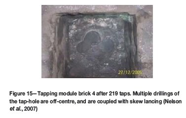
In addition, guided and stiff drill rods are essential to reducing excessive drill flex and securing a straight, centred tap-hole. Guide systems include automatic travel to within limits, followed by a hydraulic pin, sometimes colloquially called 'antlers' (Black and Bobek, 2001), being physically positioned down into latch hooks. For drilling 4 m long ironmaking BF tap-holes (requiring 6 m drill rods), additional hydraulic rod devices are fixed to the drills to prevent bending of the drill rods and drilling off the tap-hole axis (Ballewski et al., 2001). The undesirable consequence of using a less precise suspended rock drill for tap-hole drilling has been reported previously in a four-piece, water-cooled copper Ni ferroalloy tap-block operation (Nelson et al., 2007; Figure 14 and Figure 15).
An encoder that measures the drill position can be correlated with drill torque (in hydraulic systems - Jameson et al., 1999; Atland and Grabietz, 2001) or drill air-pressure forward drive (in pneumatic systems - Van Ikelen et al., 2000) and drill speed to determine automatically the start and end of the tapping channel and hence the all-important tap-hole length (Jameson et al., 1999; Van Ikelen et al., 2000; Eden et al., 2001; Tanzil et al., 2001; Edwards and Hutchinson, 2001; Smith et al., 2005). Drill-time sigma (Black and Bobek, 2001) and tap-hole length (Jameson et al., 1999) are regarded as benchmark statistics and, with the application of statistical process control (SPC), measures with which to quantify and effect tap-hole improvements.
Drill rod and bits
Drill-bit shape and material - carbide (Black and Bobek, 2001; Tanzil et al., 2001; Entwistle, 2001) or heat-resistant Cr-Ni alloy (Atland and Grabietz, 2001) tips are preferred -has been the subject of intense investigation, especially in the ironmaking BF application (Van Ikelen et al., 2000; Ballewski et al., 2001; Black and Bobek, 2001; Brunnbauer et al., 2001; Estrabillo, 2001; Entwistle, 2001; Atland and Grabietz, 2001). The ability to retain a sharp cutting edge so as to cut, rather than hammer, through the tap-hole clay 'plug', with the bit cutting face presented to a debris- and dust-free face to drill, is essential (Estrabillo, 2001). Drill-bit diameter is controlled usually within the range of 33 mm (Tanzil et al., 2001) to 45-65 mm (Steigauf and Storm, 2001; Atland and Grabietz, 2001). Where hammering is considered important, an inside bit face that is totally flat (to maximize transmission of impact energy) is reported (Tanzil et al., 2001), coupled with transition from spherical to semi-spherical carbide shapes.
Air scavenging is typically used to clear the hole, providing additionally some cooling of the drill bit to help prolong its life (Van Ikelen et al., 2000). Further improvement has involved progressively improving drill-bit cooling (from air, to nitrogen, to water mist) on ironmaking BFs (Eden et al., 2001; Petruccelli et al., 2003; Van Ikelen et al., 2000; Smith et al., 2005; Irons, 2001; Steigauf and Storm, 2001; Ballewski et al., 2001; De Pagter and Molenaar, 2001; Black and Bobek, 2001; Edwards and Hutchinson, 2001), where water-mist cooling rates are in the range of 2-5 L/min and typically 4 L/min (Tanzil et al., 2001). Water-mist cooling systems are reported to have undergone still further development to overcome disadvantages of increased risk of drill equipment corrosion (Van Ikelen et al., 2000).
In ferroalloy and matte operations, especially those equipped with any potentially hydratable magnesia-based refractory, use of any water would be taboo (in fact even to the extent that dew-point condensation associated with liquid-nitrogen cooling to accelerate tapping channel repair is sometimes a concern). The short drill-bit life is largely overcome when drilling only tap-hole clay (i.e. deliberately not drilling metal/matte/slag) in both metal/matte-only combination drilling and slag-only drilling open tapping practices.
Two opposing effects of drilling on the control of tapping channel diameter are reported. With premature bit wear, negative fluting of the tapping channel (diameter decreasing evenly down to the drill rod diameter towards the hot-face) has been reported (Van Ikelen et al., 2000). Side-cutting designs capable of cutting during both forward and reverse drilling have been developed to limit the influence of drill-bit wear on the resulting drilled diameter (Van Ikelen et al., 2000). More frequently, though, a bit that fails to retain its cutting edge tends to wander, which causes positive fluting to the hot-face (Nightingale et al., 2001; Mitsui et al., 1988; Tanzil et al., 2001), or a 'mushrooming' effect (Estrabillo, 2001; Edwards and Hutchinson, 2001). Traditional rock drill-bit designs provide some increased resistance to this, and are often preferred (Estrabillo, 2001), despite still requiring drill-bit replacement every tap on an ironmaking BF. This warrants further clarification: on ironmaking BF tap-holes the ability to open with 'one drill-bit for every attempt' is regarded as an achievement (Estrabillo, 2001), with only a 50% success rate reported at one site (Nakamura et al., 2007), or an average of 1.2 drill bits per tap reported (Atland and Grabietz, 2001). Progression from threaded to bayonet drill-rod couplings is reported (Estrabillo, 2001) to limit the incidence of drill rods jammed tightly in couplings.
The direct consequence of a smooth, straight tapping channel is a consistent smooth tapping stream and controlled post-tap-hole logistics. In contrast, a tapping channel that has an inner corkscrew shape is reported to induce a rotating and spraying tapping stream (Van Ikelen et al., 2000), an outcome exacerbated by any gas-tracking on a pressurized BF operation. 'Softer drilling' (feed-forward pressure < 3 bar) together with instructions to the operator to 'let the drill do the work' and so not try to force the tap-hole open using maximum force, which can bend the drill rod and promote a corkscrew channel, is reported to lower the incidence of rotating and spraying tapping streams (Van Ikelen et al., 2000).
This is remarkably akin to the requirements of successful oxygen lancing: a good tapper tends to use the hot burning lance tip (> 2000°C) to progressively cut the tap-hole open in a series of small precessing actions to guide the lance ever deeper to make a straight tapping channel. An inexperienced tapper, on the other hand, tends to try to force-burn the tap-hole open by pushing hard on the thin, long and flexible lance pipe, which readily causes it to deflect off-course and cause damage.
Finally, it is said that 'a rotating drilling method for opening the tap-hole, without hammering ... is expected to give an improvement of the tapping process' (Van Ikelen et al., 2000). Similarly, many local ferroalloy and PGM matte tap-holes are indeed opened by drill rotating action alone without hammer action, despite the latter's usual availability. Even on ironmaking BFs it is suggested that 'future advancements will be directed toward drilling the tap-hole without the need for hammering' (Estrabillo, 2001).
Tap-hole closure
It is essential to be able to 'close the tap-hole with a high degree of certainty that the desired volume of tap-hole clay has in fact been installed' (Tanzil et al., 2001), and additionally ensure that mudgun retraction does not result in an unplanned tap-hole re-opening. Total elimination of reopening events remains important, even given reported improvement from 10 to just one such event per annum by 2000 on one site (Black and Bobek, 2001).
Especially on slag-only closure, stopper bars, water-cooled 'rosebuds', and manual stopper tap-hole clay 'plugs' remain common in the ferroalloy and non-ferrous industry. Slightly more sophisticated variants are used on some of the lower temperature and lower superheat mattes and blister Cu operations, e.g. 'Polish plug', comprising ceramic surrounding a cone-shaped tap-hole clay 'plug' (George-Kennedy et al., 2005). Over 25% of PGM and local Ni matte operations still practise manual plugging of tap-holes (Nolet, 2014; Coetzee, 2006).
However, by far the majority of ferroalloy furnaces, 70% of PGM and local Ni matte operations (Nolet, 2014), and all ironmaking BFs have increasingly adopted sophisticated and powerful mudguns to effect tap-hole closure. Again, the importance of considering mudgun, tap-hole clay, and tap-hole operating practice holistically as a fully integrated system cannot be understated - coupling a hard new-generation tap-hole clay with an old weak mudgun incapable of properly delivering the clay into the tap-hole is bound to fail. Smith, Franklin, and Fonseca (2005) describe this well: the 'design of tap-hole clay is usually a compromise between "equipment capability" and "process" requirements.'
Mudgun equipment and operation
Manual plugging may at first glance seem extremely simplistic, requiring a direct interface of the operator with a hot tapping stream. However, if the operation is not correctly controlled, excessive tap-hole clay addition - which is possible with the use of automated mudguns - can potentially have a destructive, but often hidden, action on a tap-hole and lining environs. It was not that long ago that one of the authors witnessed a large furnace, about 30 m in length, 'disappear from view' due to excessive gas release and a concentrate blowback when a tap-hole was closed with a full 25 L mudgun load of wet clay recently 'dug from the veld'. Other observations include both metal and matte 'boils' at the back of tap-holes, tap-hole 'blows', and even gas eruption from tar binder (Mitsui et al., 1988) caused by mudgun closure involving use of excessive tap-hole clay with high loss-on-ignition content. Water flashes with a 1500-times volume increase at bath temperatures, and hydroxides, carbonates, and hydrocarbons can react almost instantaneously and decompose, devolatilize, and crack (Cassini, 2001) to release CO, CO2, H2, and/or H2O gases. In high-duty applications, tap-hole clay of low gassing potential is therefore a prerequisite, and almost all operators seek an anhydrous clay (Abramowitz et al., 1983) or 'water-free plastic mass' (Smith et al., 2005).
A perfectly cylindrical 1 m long tapping channel 50 mm in diameter requires theoretically only 2 L of tap-hole clay to completely fill it. This increases to 5 L if the tap-hole is worn on average to 80 mm diameter, by either positive fluting (exacerbated by any oxygen lancing and/or enlargement by bath wear of the tap-hole hot-face) or negative fluting down the tapping channel. Iida and co-authors (2009) even suggest that tap-hole enlargement occurs typically at a rate of 5.6 × 10⁻⁴ mm/s during tapping (1 x 10⁻³ mm/s when using 'poorer durability tap-hole mix' [Iida et al. 2009], a practice also modelled by others [Shao, 2013; Shao and Saxen, 2013b]). It is quite staggering to compare this addition with the range reported for ironmaking BFs - admittedly with tap-hole lengths of 1.8-2 m (Edwards and Hutchinson, 2001; Atland and Grabietz, 2001), or more usually 2.5-4 m (Irons, 2001) -from as little as 10-20 L (Irons, 2001) to 50-120 L (Irons, 2001; Atland and Grabietz, 2001; Van Laar, 2014; Nightingale et al., 2001; Jameson et al., 1999; Cassini, 2001) or even 200-300 L of tap-hole clay per closure when trying to stabilize a 'mushroom' (Eden et al., 2001; Irons, 2001).
In an ironmaking BF, where tap-hole clay 'mushroom' operation is feasible, several operators report stable (consistently deep) tap-hole length and reduced tap-hole clay consumption, i.e. 'not excessive addition' (Nightingale et al., 2001; Tanzil et al., 2001; Cassini, 2001), and reduction by as much as 50% to 100-120 L on a 3 m tap-hole length (Nightingale et al., 2001), which led to generally improved overall practice (Smith et al., 2005; Jameson et al., 1999; Black and Bobek, 2001; Tanzil et al., 2001; Estrabillo, 2001; Nightingale and Rooney, 2001; Bell et al., 2004; Cassini, 2001). This is particularly the case when the tap-hole-clay injection rates - rapid to assist with clean plugging of tap-hole clay down the tapping channel, yet with sufficient time for densification and crack sealing of the protective annular tap-hole-clay tapping-channel core (Andou et al., 1989; Smith et al., 2005) - and quantities added are controlled predictively, based on prior tapping and drilling metrics.
Again, this can involve SPC to control tap-hole length (e.g. to 3.1 m; Jameson et al., 1999) by varying the tap-hole clay volume (around a 100 L setpoint; Jameson et al., 1999); or by advising the operator of the recommended tap-hole clay volume after 1.5 hours of tapping, basing the advice on automatically measured tap-hole lengths and tap-hole diameter (the latter automatically inferred from measured blast pressure, liquid level, and mass tapping rates (Nightingale et al., 2001; Tanzil et al., 2001). Continuous weighing using load cells and microwave radar level detection are used to determine hot metal torpedo and/or slag-ladle filling rates, and thus related mass tapping rates (Tanzil et al., 2001; Cassini, 2001; Shao, 2013). Operation usually involves increased tap-hole clay injection when the tap-hole length decreases, and decreased clay injection when the length increases. In consecutive individual tapping practice in particular, a common additional practice advocated on the other resting tap-holes is for occasional tap-hole clay injection to maintain the 'mushroom' condition on those tap-holes, which otherwise are subject to progressive dissolution (if metal is marginally carbon-unsaturated) and wear in contact with hearth liquid (Jameson et al., 1999; Nightingale and Rooney, 2001).
Ironmaking BF experience suggests that less than one-third of tap-hole clay purchased is pushed through the gun. This wastage is ascribed to combinations of (1) incorrect storage under uncontrolled conditions of temperature; (2) the tap-hole clay getting wet; or (3) situations where the tap-hole clay is allowed to go beyond its useful shelf life. Of the remaining tap-hole clay, only 24% is estimated to be delivered into the tapping channel (Smith, Franklin, and Fonseca, 2005) (Figure 16). Nozzle cleaning, push-out waste (used to ensure that tap-hole clay is compressed in the mudgun barrel), clay leakage between the nozzle and tap-hole face (Figure 17 and Figure 18), mudgun clean-out, and 20% for 'mushroom' replacement constitute the remaining portion of tap-hole clay usage.
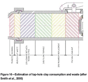
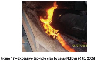
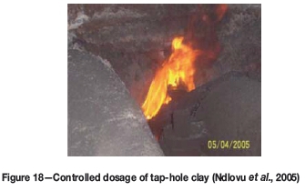
Sacrificial wooden or ceramic nozzle covers - known locally as 'dinner plates' (Ndlovu et al., 2005; Figure 19) -are commonly used to limit tap-hole clay losses associated with mudgun push-out waste (full nozzle cover) and nozzle-face/faceplate leakage (full or annular nozzle cover [Ndlovu et al., 2005; Eden et al. 2001; Jameson et al., 1999; De Pagter and Molenaar, 2001; Brunnbauer et al., 2001; Estrabillo, 2001; Bell et al., 2004]). A 25% reduction in mudgun-nozzle tap-hole clay leakage events, from a somewhat poor norm of 50%, has been reported for this practice (Estrabillo, 2001).
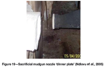
Well-designed faceplates normally further improve mating with a flat nozzle face - common on Co and Ni ferroalloy and matte-smelting operations. However, where faceplates are absent, some ironmaking BF operations have adopted tapered nozzle tips, for which better sealing against the tap-hole socket is claimed (Steigauf and Storm, 2001). Upgrading to high-nitride mudgun barrels is also cited as a factor preventing wear (Petruccelli et al., 2003; Bell et al., 2004).
On modern mudguns, rapid and automated pressure-regulated mudgun slew is applied to minimize damage to the mudgun nozzle, and to lower the risk of heavy impact on the tapping channel face and/or channel, a risk that might otherwise crack or even dislodge tap-hole refractory and the ironmaking BF 'mushroom' (Smith et al., 2005; Jameson et al., 1999). Slew pressure is usually set slightly higher than the mudgun barrel pressure (200-315 bar tap-hole clay pressure, which results in a pushing force of > 60 t on the tap-hole face/faceplate, particularly to push higher-strength tap-hole clays [Van Ikelen et al., 2000; Smith et al., 2005; Black and Bobek, 2001; Atland and Grabietz, 2001; Cassini, 2001]) - a measure that tends to limit the potential for bypass of clay between the nozzle and tap-hole face/faceplate (Eden et al., 2001; Campora et al., 1998; Jameson et al., 1999; Entwistle, 2001). Automatic control of the mudgun contact force is also preferred in order to limit the risk of undue mechanical damage to the tap-hole refractory, a control that one site achieved by a variable-machine, minimum-pressure setpoint of 150 bar plus a variable proportion of 0.3 times the plugging pressure (Ballewski et al., 2001). In the absence of rigid faceplates, tap-hole face wear can be estimated from a relationship to cylinder stroke measured by LVDT (Black and Bobek, 2001; Entwistle, 2001).
In the extreme practice of combination drill and 'plug' oxygen lance, which aims to avoid excessive tap-hole clay delivery beyond the tapping channel hot-face (for fear otherwise of the tap-hole clay boiling and ensuing damage to the tap-hole hot-face), precise control of tap-hole clay input is imperative. This often involves measurement and automated control of the injected tap-hole clay volume. Indeed, in several instances when tap-hole clay addition has been excessive (Hundermark et al., 2014; Ndlovu et al., 2005) it has been demonstrated that controlled reduction of tap-hole clay additions (closer to the volume predicted theoretically for 'normal' tap-hole dimensions) has even resulted in increased drilling depths, further enhanced by improved furnace operating control of allowable upper matte temperature (Figure 20).
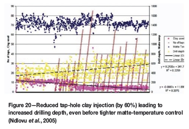
On ironmaking BF operations (Smith et al, 2005; Ballewski et al., 2001; Tanzil et al., 2001; Bell et al., 2004), staggered, multi-stage mudgun injection at different speeds can be practised to achieve optimal tap-hole conditions. This may involve (Bell et al., 2004) (1) a first fast push of 45 kg tap-hole clay to displace any other material from the tapping channel, followed by a slower push of another 45 kg clay to build the 'mushroom', and a final very slow push of variable clay mass to build the 'mushroom' still further and compact the tap-hole clay in the tap-hole, and (2) a second very slow push 5 minutes after the first push, with < 5 kg tap-hole clay added to compact the tap-hole clay still further and close voids. To diminish the risk of tap-hole breakout, the mudgun then remains in position for 5 minutes to allow adequate tap-hole clay curing before the mudgun is removed from the tap-hole face. On another operation, with a constant ram hydraulic pressure of 275 bar, a rate of tap-hole clay injection of 14 kg/s was sought (Black and Bobek, 2001).
Tap-hole clay
Tap-hole clay requirements
Typical requirements cited for tap-hole clay include the following (Abramowitz et al., 1983; Andou et al., 1989; Uenaka et al., 1989; Hubert et al., 1995; Ballewski et al., 2001; Cassini, 2001; Wells, 2002; Smith et al., 2005; Horita and Hara, 2005; Kageyama et al., 2005, 2007; Nightingale et al., 2006; Nakamura et al., 2007; Pan and Shao, 2009; Niiya et al., 2012; Kitamura, 2014):
► It should be soft and plastic enough to inject when pushed by the mudgun, but 'hard' enough to displace tapping liquid effectively and deliver a 'plug' of tap-hole clay only to the required depth in the tapping channel
► After curing, it should attain the required strength (often described as 'sinterability' [Abramowitz et al., 1983]) without shrinkage to ensure a tight seal within the tap-hole (and not prematurely in the mudgun), do so in the required mudgun dwell time, and plug the hole until the next tapping time
► It should effect safe tap-hole closure (i.e. without subsequent re-opening) without damage to the tap-hole and furnace lining (e.g. through limited gas evolution and associated turbulence), yet with the 'mushroom' remaining stable where required, e.g. in an ironmaking BF. This requires consideration of both effective tap-hole clay displacement in the injection direction (Uenaka et al., 1989; Nakamura et al., 2007; Kitamura, 2014) and a 'good spreading ability in the direction perpendicular to the injection direction' to maintain a stable 'sedimentary deposit that is gradually and stably grown' (Kitamura, 2014) and exhibiting good high-temperature adhesion to the constituents already present in the tapping channel (Niiya et al., 2012)
► It should be soft enough to be readily drilled straight down the middle of the tapping channel without deviation and in an acceptable time (this is especially important where productivity constraints exist, as in an ironmaking BF)
► It should allow a stable, controlled tapping stream flow without surging or splash (often associated in ironmaking with blast gas tracking [He et al., 2001; Pan and Shao, 2009] and gas entrained with 'viscous fingering' to above the critical value that induces a deleterious splashing casting stream [He et al., 2002; 2012], even to the extent of slug flows [Shao, 2013; Stevenson and He, 2005; Shao and Saxen 2011, 2013b])
► It should be ideally 'hard' and durable (Abramowitz et al., 1983) enough to withstand penetration, corrosion, and erosion by the tapped metal/matte and/or slag and so preserve a protective annulus between the tap stream and tap-block refractory (without additional corrosive reaction to the tap-hole refractory), thereby extending the useful life of the tapping channel with an acceptable, controlled diameter, shape (i.e. minimal long-term fluting), and length.
To ensure optimal tap-hole clay quality, additional measures for tap-hole clay preparation are recommended (Black and Bobek, 2001; Delabre et al., 1991; Hubert et al., 1991). These measures may include a stand-alone tap-hole clay storage building, maintaining a 10-day supply of tap-hole clay, and controlling the temperature in the building and the in-process temperature for storing tap-hole clay at the tap floor to 25-30°C (Abramowitz et al., 1983). Maturation of the clay as a function of the binder quantity and type for two months is reported (Delabre et al., 1991) to permit one clay to attain desired plasticity properties, these properties also being dependent on storage conditions. On the other hand, prolonged storage of resin-bonded tap-hole clay, especially at temperatures exceeding 40°C, is reported specifically as being detrimental to its performance (Wells, 2002). However, especially for tar-bonded tap-hole clays, a minimum of 15 days' ageing is reported as essential to secure adequate tap-hole clay loss in plasticity and increased hardness (Hubert et al., 1995). A tap-hole clay producer even reports forced cooling of tap-hole clay to avoid any risk of continued undue temperature rise before final packaging of product (Nakamura et al., 2007).
Tap-hole clay aggregate
Most technical developments of tap-hole clay originate from the ironmaking BF industry, where the high productivity (10 000 t/d HM), combined metal and slag duty, high pressure (approx. 10 bar at tap-hole - Van Laar, 2014), and long tap-hole length (2.5-4 m - Table I) make high demands on tap-hole clay quality. Mitsui and co-workers (1998) use lowering of specific tap-hole clay consumption (kg/t HM) to outline early developments from the 1970s to 1988. These include a progression from coke, to alumina, to silica, and back to pitch-impregnated alumina (Niiya et al., 2012) and high-alumina clays comprising a fine matrix (< 45 μm and > 50% by mass [Kageyama et al., 2007; Horita and Hara, 2005]) and/or coarser aggregates (1-3 mm and approx. 20% by mass [Horita and Hara, 2005]). These clays include variously additions of zirconia, kyanite (Andou et al., 1989), SiC, and metals or nitrides of silicon, aluminium, and ferrosilicon. These elements and compounds are added as fine powders to the matrix to lower porosity, reduce shrinkage, decrease volatiles, increase antioxidant action, lower wettability by slag, and improve extrudability, sintering, and resistance to corrosion and erosion (Abramowitz et al., 1983; Andou et al., 1989; Uenaka et al., 1989; Black and Bobek, 2001; Wells, 2002; Smith et al., 2005; Kageyama et al., 2007; Nakamura et al., 2007; Pan and Shao, 2009; Niiya et al., 2012; Kitamura, 2014). Mention is also made of a trend to smaller particle size for improved compaction (Black and Bobek, 2001) and better sealing of the tapping channel against gas egress (Pan and Shao, 2009). Some sources even claim that ultrafines (< 10 m [Kageyama et al., 2007]) improve strength, resistance to corrosion and abrasion, and an 'ability to go straight during gun-up instead of extending transversely inside the furnace' (Nakamura et al., 2007). Improved corrosion resistance and higher positive residual expansion coefficients of pure silica and pure alumina sources compared with aluminosilicates are also reported (Mitsui et al., 1998). Such a 'swelling' characteristic (Mitsui et al., 1998; Cassini, 2001; Nightingale et al., 2006) is important for helping to seal a tap-hole subject to temperature fluctuation from the extreme of superheated tapping temperatures to cold closure conditions in water-cooled tap-blocks. Additives are also beneficial in instances where the clay has not fully baked before the next tap, and provide strength at lower clay temperatures (Delabre et al., 1991). A somewhat more empirical approach has similarly led to convergence on the use of tap-hole clays of high alumina content for high-intensity operations in the local pyrometallurgical industry.
Tap-hole-clay binder
Traditionally, coal tar pitch was used as a binder (approx. 20% by mass [Kageyama et al., 2005]) in tap-hole clay. This was followed by a period in the 1990s where phenolic resin found favour. By 2001 it was reported that 90% of Japanese ironmaking BFs (Irons, 2001) and a Canadian producer (Bell et al., 2004) had reverted to tar-bonded tap-hole clay, while in Europe tar, resin, and resin-tar binder combinations all continued to find favour (Irons, 2001). By 2005 one supplier of tap-hole clay reported that only two ironmaking plants in Japan were using resin-bonded tap-hole clay (Horita and Hara, 2005).
Tar-bonded tap-hole clays are generally thermoplastic, hard (often requiring pre-heating of the tap-hole clay in the mudgun barrel by gas heaters, hot water, or steam to become pliable [Ballewski et al., 2001], especially for operation in colder climates), and slower curing (a cast time of 2 hours is deemed insufficient for full curing and sintering [Black and Bobek, 2001], although only 20-30 minutes is frequently encountered as being available for curing in practice [Uenaka et al., 1989; Shao and Saxen, 2011, 2013a; Shao, 2013]). Slow curing necessitates the mudgun remaining in position for an extended time after plugging to avoid the tap-hole reopening unintentionally. Unlike resin binders, tar-bonded tap-hole clay is reported to have the advantage of forming a transition-free union with a carbon-based refractory, which results in a monolithic tap-hole lining (Ballewski et al., 2001) and improved adhesiveness at high temperatures (Niiya et al., 2012). Radiant heating from the tapping launder may necessitate protection of the barrel by metal or ceramic insulating shields (Bell et al., 2004), or even water-cooling. Mudguns with a partial or full circumferential water jacket and dual heating/cooling systems are quite common in ironmaking BFs and some Cr and Mn ferroalloy operations. These systems are often automated to operate at a fixed temperature setpoint, e.g., a constant 50-65°C (De Pagter and Molenaar, 2001; Ballewski et al., 2001; Bell et al., 2004; Atland and Grabietz, 2001); or for maximum flexibility an adjustable, controlled temperature range, e.g., 25-90°C (Black and Bobek, 2001) is provided for and tailored specifically to a given tap-hole clay type in use (Campora et al., 1998). A reduction in tap-hole clay consumption by wastage of between 10 and 30% is reported in uses of water-cooled mudguns (Ballewski et al., 2001; Atland and Grabietz, 2001).
Resin-bonded tap-hole clays are faster curing (Uenaka et al., 1989; Wells, 2002; Kageyama et al., 2005), a property promoting shorter mudgun dwell time and quicker tap-hole turnaround (of importance in a high-productivity operation such as an ironmaking BF). Occasionally, though, the tap-hole clays can cure too quickly, which leads, in hotter tap-holes, to the clay curing before injection is complete (Jameson et al., 1999; Nakamura et al., 2007); or, in the extreme, to its blocking prematurely in an excessively hot mudgun barrel and possibly delaying an effective tap-hole closure. Resin-bonded tap-hole clay can be prone to greater volatility upon heating (Kageyama et al., 2005), to more undesirable gas evolution (observed in local industry), and is generally softer (to the extent of being found incapable of effecting tap-hole closure on some high-temperature and superheated Cr metal-only and PGM matte-only tap-holes). Some resin-bonded tap-hole clays have also been reported to cure too hard for acceptable drill times (< 15 minutes), a development requiring binder reformulation (Nakamura et al., 2007). In high-intensity PGM matte operations, the risk of failing to close timeously a 'vicious' superheated tap is considered so extreme that procedures further dictate that no matte tap-hole be opened without the availability of two fully prepared mudguns loaded with tar-bonded tap-hole clay to close the matte tap-hole.
Ballewski and co-workers (2001) observe that generally 'the lower the temperature, the more difficult the correct choice of a binder system for mud becomes . . . otherwise the front tap-hole area would extend negatively on the cold side'. Ostensibly for other reasons, just such a tap-hole extension outside the furnace (colloquially described as a bullnose, Figure 8) is precisely what has tended to happen with intensely cooled copper tap-blocks.
Abramowitz and co-workers (1983) reported that 'small changes (< 5%)' in either light oil loss (260°C for 6 hours) or loss on ignition (defined by them at a temperature of 1204°C, rather than a more common 900°C, or 1000°C [Hubert et al., 1995]) can 'change many dimensional and strength properties (as high as 119%)' of tap-hole clays. This emphasizes the need for close control of conditions in the manufacture of all tap-hole clays, if one is to yield a product of consistent quality. Using cold crushing strength (> 7.6 MPa) and workability (18-28%) as quality criteria in the early 1980s, tap-hole clay manufacturers found that tap-hole clay rejection rates of up to 40%, sometimes more, were not uncommon. Rejection rates below 15% were suggested as acceptable.
In the local industry, variable supply and quality of coal tar pitch has at times led to suboptimal 'cutting' additions of oils to overly viscous pitch, with additions of resin to try to restore curing times. With binder additions of typically 20% by mass (Kageyama et al., 2007), this has often led to tap-hole clays being prone to excessive gas evolution and having suboptimal handling and plugging characteristics, properties that make the clay possibly suitable for less onerous slag tap-hole closure, but unsuitable for high-duty, superheated Cr metal-only and PGM matte-only applications.
Tap-hole clay health issues
While imposing a minimum 45-minute tap-hole clay curing time before re-drilling and tapping is reported to result in less emission of fumes (Estrabillo, 2001), tar binders pose health risks through the release of polycyclic aromatic compounds such as benzopyrene, which are carcinogenic (Perez et al., 2001; Hershey et al., 2013; Irons, 2001). The release of similarly undesirable formaldehydes and phenols is associated with resin binders. Molenaar (Irons, 2001) argues that benzopyrene particles in the air condense on dust, and hence some protection is afforded by wearing a mask, which is ineffectual for protection against formaldehyde and phenol gases.
Non-polluting tap-hole clay is therefore desirable, provided that it can adequately meet the arduous duty and requirements of tap-hole clay without introducing further risk (e.g. tap-hole liquid breakout). Tarless tap-hole clays have been available since the 1970s (Hubert et al., 1991), as well as tap-hole clay utilizing commercial tar binder of 'one thirtieth of the benzopyrene' content of ordinary coal tar for binders (Kitamura, 2014). More recently clays which do not contain any polycyclic aromatic hydrocarbons have also become available (Lungmuß Feuerfest, 2014). However, it was reported (Perez et al., 2001) that non-polluting singlephase binders have proved unsuccessful, but that a single-phase binder A plus binder B (made of several mixtures) manifested comparable plasticity, high-temperature adhesivity, high thermal expansion, and low erosion properties to existing tap-hole clays.
Industry's adoption of non-polluting tap-hole clays has not been universal. This is possibly owing to concerns regarding some perceived deficiencies in their performance in tap-hole duty for certain commodities compared to more traditional tar-based clay products.
Tapping and tap-hole environment
Tap-hole opening, the act of tapping metal/matte/slag, and tap-hole closure all lead to increased environmental emissions around the furnace. That is, emissions associated with drilling uncured tap-hole clay, or fumes released in oxygen lancing; release of process gases such as CO or H2 under pressure, especially in ironmaking BFs, or SO2, possibly even H2S, by release or reaction, especially in matte smelting, but also other trace gases, e.g., Cl and F, or contained volatile heavy metal impurities, e.g. Pb, As, Cd, and Zn, depending on specific composition; and volatile emissions from injecting tap-hole clay. Extraction systems on tap-hole, launder, and ladle hoods (Figure 1), and even on entire tapping aisles, are increasingly required to achieve the necessary and acceptable workplace hygiene and environmental abatement.
Tap-hole maintenance and life
Preventative maintenance
Ironmaking BFs incorporate robust designs that usually last for more than 10 years with little maintenance reported (Steigauf and Storm, 2001) of the castable at the front cold-face (and without 'mickey' bricks). An original four-tap-hole construction that lasted 12 years is also reported. Other BF sites report a 28-day cycle of casting tap-hole pairs (Steigauf and Storm, 2001), or recasting of tap-hole faces in planned maintenance scheduled every 18 weeks (Tanzil et al., 2001). Tap-block graphite block inspection every 4 years is also reported (Black and Bobek, 2001).
Longer time-frames and operation to tap-hole breakout (usually within 3-4 years) are also practised on many local ferroalloy furnaces, but usually with the consequence of far more severe furnace lining damage and shortened cycle times to the next breakout. A notable exception is a campaign life of 9-12 years before a first small tap-hole repair, reported on combined metal-slag tap-holes of freeze lining design on a Cr ferroalloy furnace (Duncanson and Sylven, 2011). On Cr ferroalloy furnaces with water-cooled copper tap-block elements, other periodic planned maintenance may present ideal opportunities to effect annual slag tap-block and/or biannual metal tap-block repairs.
Most typically in Mn ferroalloys, total furnace (and by inference tap-hole) life is reported as being only 6-10 years (De Kievit et al., 2004; Van der Walt, 1986; Hearn et al., 1998), with some early freeze lining furnace designs giving over 20 years of life being the exception (Van der Walt, 1986; Hearn et al., 1998). On many Mn ferroalloy furnaces, periodic 'mickey' block replacement may be planned and performed as often as every 6 months, with a tap-block campaign life of three years being typical. With the freeze lining tap-hole design, life in excess of 18 months for the annular replaceable carbon block and graphite sleeve design has been reported in SiMn production (Hearn et al., 1998), and 400 mm (out of 870 mm) wear of tap-block hot-face in just over three years of service is reported in HC FeMn production (O'Shaughnessy et al., 2013). Apparently this wear is not attributed to erosion by tapping practices alone (which involve drilling and minimal use of oxygen lancing); rather, it is suspected that standard furnace thermal equilibrium conditions do not always permit the tap-holes to remain at their design length (O'Shaughnessy et al., 2013). On Mn ferroalloy furnaces with water-cooled copper tap-block elements, planned maintenance activities are understandably more aggressive, with 'mickey' repairs being carried out as frequently as every 4 months.
Blister tap-holes were reported to operate for 8 000 t between inner change, while flash converting furnaces were projected to deliver more than 4 years of life (George, 2002). The latest furnace life estimate is now in excess of 5 years (George-Kennedy et al., 2005).
On Ni ferroalloy and Ni and PGM matte furnaces, preventative maintenance may be time-based on lower intensity furnaces, but is more usually based on number of taps (Nolet, 2014; Jastrzebski et al., 2012) rather than on mass tapped, with the assumption that a 'tapping event' (comprising tap-hole opening, tapping, and tap-hole closing) is a more significant determinant of tap-hole wear than the mere act of tapping. As previously intimated, especially on higher-intensity superheated PGM matte operations, excessive tapping rates can also be used to trigger tap-hole maintenance.
Typical tap-hole maintenance cycles that result are 1-4 weeks between faceplate refractory insert and shallow tapping module brick replacement; quarterly for deep tapping module and/or surround brick replacement; 1-2 years for full tapping channel repair and potentially water-cooled copper tap-block replacement (Nolet, 2014).
In addition, condition-based maintenance can be triggered immediately by any of the following: suspicion of any water leak; overly skew drilling; overly skew lancing (less easy to diagnose); excessive oxygen lance consumption; undue difficulty in tap-hole closure by tap-hole clay; damaged faceplate refractory insert; damaged faceplate (the flat, vertical, mating surface presented to the mudgun nozzle is compromised); the insert tapping channel diameter is greater than a prescribed limit (practice requires the oversize diameter to be followed down the tapping channel, replacing adjacent tapping module bricks until the diameter is deemed within a prescribed limit); and tap-hole temperature spikes reaching above alarm limits.
Special maintenance
Online repair techniques to improve the tap-hole condition on ironmaking BFs include (Yamashita et al., 1995; Jameson et al., 1999; Ballewski et al., 2001) the following: use of higher plasticity tap-hole clays to help seal gaps and reconstruct 'mushrooms'; use of an emergency 'nozzle can' (Estrabillo, 2001); injection of resin down a partially drilled (blind) tap-hole to seal cracks and reduce gas tracking; and grouting through injection under pressure of tar-bonded carbon mortars to fill voids more generally and so re-establish thermal contact and reduce gas tracking (Edwards, and Hutchinson, 2001). Details of several grouting and zoned-plug (blind) repairs and basic procedures in ironmaking BFs are described by Cámpora and co-workers (1998), Yamashita and co-workers (1995), and Ballewski and co-workers (2001). A caution is sounded: great care should be exercised in grouting, using a sufficient number of open grouting points in the repair vicinity, to avoid the risk of grouting leading to excessive build-up of pressure and so leading inadvertently to refractory movement and even to lining failure.
A comprehensive mudgun and drill inspection programme, with weekly, monthly, quarterly, and annual activities to ensure equipment reliability, and early detection and prevention of possible failures, is described by Petruccelli (2003). Reliability of air supply on pneumatic drills is quoted fairly frequently as a cause of poor drilling, with air accumulators and new compressors being installed to address the problem (Petruccelli, 2003).
Tap-hole monitoring
Standard tap-hole monitoring
Three general levels of tap-hole monitoring are identified:
► Limited use of single thermocouples inserted into the lining, some around the tap-hole, often associated with a furnace campaign (let alone tap-hole) life of under 6 years on both (historically) ironmaking BFs (Eden et al., 2001; Jameson et al., 1999) and ferroalloy furnaces (Van der Walt, 1986; Hearn et al., 1998; De Kievit et al., 2004; Coetzee and Sylven, 2010; Coetzee et al., 2010; Duncanson, and Sylven, 2011)
► Progression to more thermocouples (15-50), predominantly duplex in configuration, to permit heat flux calculations and monitoring on ironmaking BFs (Stokman et al., 2004; Jameson et al., 1999; Irons, 2001; Entwistle, 2001) and ferroalloy furnaces (De Kievit et al., 2004). Furnace campaign life now ranges more typically between 10 and 20 years on both ironmaking BFs (Van Laar et al., 2003; Eden et al., 2001; Jameson et al., 1999) and ferroalloy furnaces (Van der Walt, 1986; Hearn et al., 1998; De Kievit et al., 2004; Duncanson and Sylven, 2011)
► Dedicated multiple thermocouples for in-tap-hole temperature measurement (Estrabillo, 2001), heat flux probes (equipped with thermocouples) (Atland and Grabietz, 2001), and, in the extreme, up to 30 copper thermocouples and water circuit RTDs (to determine temperatures, and water temperature rises and associated local heat fluxes) to monitor water-cooled copper tap-blocks (let alone the adjacent furnace lining), practices that are adopted on some high-intensity non-ferrous operations.
Advanced tap-hole monitoring
Conditions inside the tap-hole during tap-hole clay curing can be determined by drilling a pilot hole and
► Inserting temporary thermocouples down the tapping channel to determine tap-hole temperature profiles with depth, e.g. on ironmaking BFs temperatures rise on average from 200 to 800°C (maximum 550 to 1200°C) from 0.25 to 1.75 m down the tap-hole (Abramowitz et al., 1983; Delabre et al., 1991; Campora et al., 1998; Ballewski et al. 2001; Nightingale et al., 2006; Niiya et al., 2012), thereafter reaching a plateau down the 3 m long tap-hole (Ballewski et al. 2001) and with time (700- 900°C within 30 minutes of injection (Entwistle, 2001), and applicable to establishing tap-hole-clay set-up times (Abramowitz et al., 1983; Mitsui et al., 1988; Delabre et al., 1991; Campora et al., 1998; Ballewski et al., 2001; Bell et al., 2004; Niiya et al., 2012)
► Measuring with a contact thermocouple at 20 cm intervals, even reported apparently in normal opening of the tap-hole (Ballewski et al. 2001)
► Inserting nitrogen-cooled (Entwistle, 2001) or water-cooled (Ballewski et al., 2001) fibre-optic cameras to view internal tapping channel conditions
► Core drilling the curing/cured tap-hole clay samples for chemical and mineralogical/petrographic analysis and physical testing (Andou et al., 1989; Van Laar et al., 2003; Shao, 2013), sometimes on a two-year planned maintenance cycle (Bell et al., 2004).
In some BF stacks ceramic rods are integrated into the lining to permit wear to be determined by the ultrasonic measurement of rod length (here one assumes ceramic wear is coincident with lining wear [Stokman et al., 2004]). What is uncertain is the status of the application and the efficacy of this or any alternative, external, nondestructive testing (NDT), acoustic emission (AE) technique (Sadri et al., 2008; pers. comm. 2010, 2011) in more intensely cooled tap-hole regions, frequently with the presence of composite refractory materials and/or water-cooled copper coolers.
A more recent development has been the use of electrical resistance-based sensors (continuous along the length of the sensor, but for peak temperature only [Hopf and Rossouw, 2006]) and fibre-optic temperature sensors (either continuous sensor length maximum temperature, or discrete [about 25 per sensor] temperature measurements [Gerritsen et al., 2009; Hopf, 2014; pers. comm. 2010]) to record more accurately and better map matte (and slag) tap-block temperatures in Ni and PGM matte smelting.
This development is an attempt to avoid a 'porcupine' copper tap-block containing more conventional copper thermocouples and water RTDs than available for labelling by the alphabet! This recognizes the limited range (akin to 'fishing with a rod' [Wasmund, 2003], so raising the chance of missing vital information) of only local temperature detection by thermocouples in an intensely water-cooled copper tap-block environment. Tap-blocks are often equipped with yet a third redundant cooling circuit recessed towards the cold-face. This circuit has been successfully used on at least one occasion as a backup water circuit that permitted the safe shutdown of the furnace under controlled conditions following a cooler 'hit' and the loss of the primary hot-face cooling water circuit and/or furnace refractory breakout. This further recognizes the more global monitoring capability, but poorer temperature resolution, of a rise in cooling water temperature on intensely cooled copper tap-blocks (akin to 'fishing with a net' [Wasmund, 2003], so being better at capturing key thermal events).
Although conventional duplex thermocouples are capable of detecting the accumulation of thermal energy in tap-hole refractories when tapping in close succession on one matte tap-hole (Figure 10 and Figure 21), fibre optics provide more detailed local mapping of the distributions and rises in temperature associated with consecutive tapping. Alternatively, the beneficial effects of resting a tap-hole to lower temperatures, as practised in alternating tapping procedures, may require less exhaustive monitoring (Figure 11).
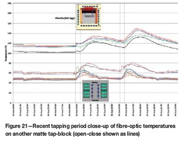
Preliminary results seem to confirm a distinct temperature rise following tap-hole closure, consistent with the previously observed heat load rise following tap-hole closure (Cameron et al., 1995). Cooling during tapping was also reported (Figure 22). The former was plausibly ascribed to the significantly increased heat flux associated with tap-hole clay coming into contact with superheated matte and the associated turbulence of gas bubbles and concomitant enhanced heat transfer. The cause of the latter is unknown.
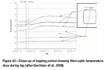
Depending on whether temperatures are measured at the chamfer or in the tapping channel during tapping on another matte tap-hole (Figure 21), recent fibre-optic measurements seem to show some trends of rising temperatures (and only sometimes falling) already during tapping. Temperatures continue at best on a similar trajectory, rather than with any distinct rise as may be expected for tap-hole clay closure (tapping events being determined from pyrometer temperature data). Moreover, while it may be tempting to ascribe apparent minor temperature dips around some tap-hole closure events to a theoretically plausible effect of tap-hole cooling by the injection of tap-hole clay (modelled in SiMn ferroalloy tapping [Muller and Steenkamp, 2013]), closer analysis suggests that the apparent dips are more likely to be an artefact of cooling induced periodically by the coarse temperature control of the copper tap-block water-cooling heat-exchanger circuit.
Clearly, still more work is required to understand and explain fully the tap-block fibre-optic temperature trends. This is a fundamental requirement prior to attempting more complex projections of possible tap-hole brick wear trends by thermal modelling - projections in support of advanced condition monitoring.
In response to difficulties and risks in the timeous detection of a significant tap-block temperature rise (see Dedicated metal/matte tapping section), other more advanced monitoring and diagnostic systems have been pursued, including principal component analysis (PCA), to try to provide some advanced view of the development of some abnormal tap-hole conditions (Gerritsen et al., 2009; Plikas et al., 2005; pers. comm., 2010), and tap-hole acoustic monitoring (TAM), which has the potential to identify the development of off-centre lancing (Sadri et al., 2008; Wasmund, 2003; pers. comm., 2010, 2011).
Tapping system water hazards
Given the sheer rapidity, often with very limited warning, and consequences of a matte/blister Cu 'hit' of a water-cooled furnace component, it is quite simply deemed that refractory or accretion freeze lining must always persist to prevent such direct matte/blister Cu contact with the copper tap-blocks, a condition somewhat analogous to protection against the physical cause of loss of the space shuttle Columbia, being a 'breach in the Thermal Protection system' (Gehman et al., 2003). This disaster involved the loss of thermal protection tiles; the analogy to protective refractory layers in a composite copper cooling system is patent. A final critical warning served on all furnace operating and maintenance personnel is a learning outcome from the Columbia disaster: avoid falling into the trap of complacency by analogously 'deeming damage to the Thermal Protection System an "accepted flight risk"' (Gehman et al., 2003). Any decision not to investigate thoroughly a suspected matte/blister Cu 'hit', or breach of protective refractory and/or accretion freeze lining, should always be challenged with vigour!
Alternative coolants are suggested as a means to mitigate some of the risks associated with linings that use water cooling in high-temperature molten-bath systems (Kennedy et al., 2013). Certainly until such cooling media achieve common commercial application, effective water leak detection is a vital safety requirement of designs that incorporate water-cooled linings. Monitoring of abnormal drops in temperature in tap-holes or linings through cooling by water (Jameson et al., 1999; Nelson et al., 2004) or of abnormal rises in temperature, either through conversion to steam and its subsequent transport and heating effect in the nearby environs, or through the loss of the freeze lining skull (Entwistle, 2001), is another procedure adopted to identify water leaks. Other methods involve off-gas analysis for increased hydrogen content (in reducing ironmaking BF and ferroalloy processes) or, directly, for water vapour using hygrometers.
Systems that require closed-circuit water cooling need to take the following into account: monitoring frequency, the rate of change of make-up water, and the standpipe level to detect leaks (Jameson et al., 1999; pers. comm. 2010); differential flow (MacRosty et al., 2007; pers. comm. 2010) and multi-tier sensors that involve the monitoring of copper and water temperatures, water flow, and (periodically) water pressure (Valentas and Thierney, 2010; shaw et al., 2013; Bussell et al., 2013). Such automated pressure testing of individual cooler-water circuits (at operator-selected scan rates) has proved capable of detecting even the smallest of 'drip' leaks on commercial furnaces (Shaw et al., 2013). These systems are most direct and effective, but more expensive and, for safety, dependent on coolers equipped with redundant water-cooling circuits and/or process and cooler design conditions in which the termination of a cooler water circuit supply for a brief period of pressure testing carries no risk of converting water so entrapped to steam.
Conclusions
The critical importance of tap-hole design and management to furnace performance and longevity on a variety of ferrous and non-ferrous smelting processes has been demonstrated. Process conditions and productivity requirements dictate specific differences and similarities in tapping equipment and practices, and in managing tap-hole operations and maintenance. Operators are challenged to benchmark continually against other established best tapping practices and tap-hole management systems in order to seek further incremental improvements in safety and performance.
Molenaar's vision (Irons, 2001) of the tap-hole of the future, now well over a decade old, was of a fully automated and remote-controlled environment. This effectively describes operating with personnel safely removed to the maximum extent possible from direct interface with hot liquids, their containment systems (hot lining and environmental), and tapping systems. While progress has indeed been made in this direction, further effort is required to realize such an ideal, consistent with still further improvements in tap-hole performance and life, improvements that are pivotal to ensuring the safest and highest productivity furnace tapping operation possible.
Acknowledgments
Permission by Anglo American Platinum Ltd. to publish, technical discussions and contributions by Reinoud van Laar, Paul den Hoed, Bart Pieterse, Alpheus Moshokwa, Phillimon Mukumbe, Joalet Steenkamp, Paul van Manen, and Whitey Seyanund, and assistance with manuscript preparation by Emerelda Kieser are gratefully acknowledged.
References
Abramowitz, H., Goffney, L.J., and Ziegert, W.L. 1983. Taphole mix properties and performance for the first year of operation on Inland's No. 7 blast furnace. Proceedings of the 42nd Ironmaking Conference, Atlanta, GA, 17-20 April. Iron and Steel Society of AIME, Warrendale, PA. pp. 681-694. [ Links ]
Ando, J. 1985. Development of slag blast granulating plant characterised by innovation of the slag treatment method, heat recovery and recovery of slag as resources. Mitsubishi Heavy Industries, Ltd., Technical Review, June. p. 7. [ Links ]
Andou, T., Nagahara, M., Tsutsui, N., Ikeda, M., Nomura, M., and Suetaki, T. 1989. Wear mechanism of taphole mix. Nippon Steel Technical Report, no. 41. pp. 7-11. [ Links ]
Atland, R. and Grabietz, G. 2001. Tap-hole design and experience. Proceedings of the McMaster Symposium on Iron and Steelmaking. pp. 211-230. [ Links ]
Ballewski, T., Peters, M., Ruther, P., and Schmole, P. 2001. New improvements of the tap-hole area at Thyssen Krupp Stahl AG. Proceedings of the McMaster Symposium on Iron and Steelmaking. pp. 48-56. [ Links ]
Bell, C., Boettcher, B.D., Hribljan, F., Kinsman, B.M., and Van Laar, F. 2004. Tap-hole maintenance improvements at Dofasco. AISTech, vol. 1. pp. 303-321. [ Links ]
Black, B. and Bobek, J. 2001. Improvement in tap-hole life and casting performance at Ispat Inland's no. 7 BF. Proceedings of the McMaster Symposium on Iron and Steelmaking. pp. 156-176. [ Links ]
Brown, R.W. and Steele, D.F. 1988. Bond developments in silicon carbide blast furnace refractories during the 1980's. Aachen Proceedings. pp. 41-46. [ Links ]
Brunnbauer, G., Mauhart, J., Ferstl, A., Nogratnig, N., and Rummer, B. 2001. Tapping practice at Voest Alpine Stahl Linz. Proceedings of the McMaster Symposium on Iron and Steelmaking. pp. 178-182. [ Links ]
Bussell, B., Janzen, J., St. Amant, M., Miron, R., Emond, M., Braun, W., and GERRITSEN, T. 2013. Improved furnace cooling water pressure leak detection system at VALE. Proceedings of INFACON 13, Almaty, Kazakhstan. pp. 377-384. [ Links ]
Cameron, I.A., Sriram, R., and Ham, F. 1995. Electric furnace matte tap hole developments at Falconbridge Limited. CIM Bulletin, vol. 88, no. 991. pp. 102-108. [ Links ]
Campbell, A.P., Pericleous, K.A., and Cross, M. 2002. Modeling of freeze layers and refractory wear in direct smelting processes. Iron and Steelmaker, vol. 29, no. 9. pp. 41-45. [ Links ]
Campora, S., Doro, E., Giandomenico, F., and Gonzalez, J.M. 1998. Improvements on the cast house operation at Siderar's blast furnace #2 since the blow-in. Proceedings of the 57th Ironmaking Conference, Toronto, 22-25 March 1998. pp. 203-217. [ Links ]
Cassini, C. 2001. Tap-holes operating and face repair practices at Sollac-Mediterranée FOS Plant. Proceedings of the McMaster Symposium on Iron and Steelmaking. pp. 68-80. [ Links ]
Coetzee, C. and Sylven, P. 2010. No tap-hole - no furnace. Proceedings of Refractories 2010. Southern African Institute of Mining and Metallurgy, Johannesburg. pp. 55-66. [ Links ]
Coetzee, C., Duncanson, P., and Sylven, P. 2010. Campaign extension for ferroalloy furnaces with improved tap hole repair system. Proceedings of INFACON XII, Helsinki. pp. 857-865. [ Links ]
Coetzee, V. 2006. Common-sense improvements to electric smelting at Impala Platinum. Journal of the Southern African Institute of Mining and Metallurgy, vol. 106, no. 3. pp. 155-164. [ Links ]
Dash, S.K., Jha, D.N.S., Ajmani, K., and Upadhyaya, A. 2004. Optimisation of tap-hole angle to minimise flow induced wall shear stress on the hearth. Iron and Steelmaker, vol. 31, no.3. p. 207-215. [ Links ]
De Kievit, A., Ganguly, S., and Dennis, P. 2004. Monitoring and control of furnace 1 freeze lining at Tasmanian electro-metallurgical company. Proceedings of INFACON X, Cape Town. pp. 477-487. [ Links ]
De Pagter, J. and Molenaar, R. 2001. Tap-hole experience at BF6 and BF7 of Corus strip products Ijmuiden. Proceedings of the McMaster Symposium on Iron and Steelmaking. pp. 107-125. [ Links ]
Delabre, Ph., Dufour, A., Guenard, C., Hitier, B., Hubert, P., Le Runigo, I., and Venturini, M.J. 1991. Taphole mud: a refractory key control of blast furnace casting conditions. Proceedings of the Unite CR Congress. pp. 299-305. [ Links ]
Duncanson, P.L and Sylven, P. 2011. New refractory lining direction at Jindal stainless - first Indian FeCr producer to install UCAR Chillkote® linings. GrafTech International. pp. 2-10. [ Links ]
Eden, M.G., Ferstl, A., and Doel, P. 2001. The tap-hole zone of a blast furnace - the critical region for a long campaign life. Proceedings of the Third IAS Ironmaking Seminar, Buenos Aires, Argentina. pp. 123-130. [ Links ]
Edwards, B. and Hutchinson, S. 2001. Emergency tap-hole repair No. 4 Blast Furnace at STELCO Hilton Works. Proceedings of the McMaster Symposium on Iron and Steelmaking. pp. 273-290. [ Links ]
Entwistle, J.W. 2001. The tap-hole: A unique system. Proceedings of the McMaster Symposium on Iron and Steelmaking. pp. 243-258. [ Links ]
Estrabillo, L.S. 2001.Tap-hole management practices at Lake Erie steel company. Proceedings of the McMaster Symposium on Iron and Steelmaking. pp. 233-241 [ Links ]
Fallah-Mehrjardi, A., Hayes, P., and Jak, E. 2014. From phase equilibrium and thermodynamic modeling to freeze linings - the development of techniques for the analysis of complex slag systems. Celebrating the Megascale: Proceedings of the EPD Symposium on Pyrometallurgy in Honor of David G.C. Robertson. TMS, Warrendale, PA. pp. 259-266. [ Links ]
Gehman, H.W., Barry, J.L., Del, D.W., Hallock, J.N., Hess, K.W., Hubbard, G.S., Logsdon, J.M., Osheroff, D.D., Ride, S.K., Tetrault, R.E., Turcotte, S.A., Wallace, S.B., and Widnall, S.E. 2003. Report of Columbia Accident Investigation Board. National Aeronautics and Space Administration, Washington, DC. http://s3.amazonaws.com/akamai.netstorage/anon.nasaglobal/CAIB/CAIB_lowres_full.pdf [ Links ]
George, D.B. 2002. Continuous copper converting - A perspective and view of the future. Sulfide Smelting 2002, Proceedings of a Symposium held during the TMS Annual Meeting, 17-21 February. pp. 3-13. TMS, Warrendale, PA. [ Links ]
George-Kennedy, D., Walton R., George, D.B., and Nexhip, C. 2005. Flash converting after 10 years. Proceedings of the 11th International Flash Smelting Congress, Bulgaria/Spain. pp. 79-97. [ Links ]
Gerritsen, T., Shadlyn, P., Macrosty, R., Zhang, J., and Van Beek, B. 2009. Tapblock fibre-optic temperature system. Proceedings of Pyrometallurgy of Nickel & Cobalt 2009. pp. 627-639. [ Links ]
Gudenau, H.W., Krónert, W., and Fusenig, R. 1988. Wear profiles in blast furnace hearth, giving particular consideration to the formation of blast furnace salamander. Aachen Proceedings. pp. 28-31. [ Links ]
Guevara, F.J. and Irons, G.A. 2007. Slag freeze layer formation in an electric smelting furnace. Proceedings of Cu2007. Carlos Díaz Symposium on Pyrometallurgy, Toronto. vol. 3 (book 2). pp. 481-493. [ Links ]
Guthrie, R.I.L. 1992. Engineering in Process Metallurgy. Oxford Science Publications. [ Links ]
He, Q., Zulli, P., Tanzil, F., Lee, B., and Evans, G. 2001. An insight into flow behaviour of blast furnace taphole streams. Proceedings of the McMaster Symposium on Iron and Steelmaking, no. 29. pp. 149-153. [ Links ]
He, Q., Zulli, P., Tanzil, F., Lee, B., Dunning, J., and Evans, G. 2002. Flow characteristics of a blast furnace taphole stream and its effects on trough refractory wear. 1S1J International, vol. 42, no. 3. pp. 235-242. [ Links ]
He, Q., Evans, G., Zulli, P., and Tanzil, F. 2012. Cold model study of blast gas discharge from the tap-hole during the blast furnace hearth drainage. ISIJ International, vol. 52, no. 5. pp. 774-778. [ Links ]
Hearn, A.M., Dzermejko, A.J., and Lamont, P.H. 1998. 'Freeze' lining concepts for improving submerged arc furnace lining life and performance. Proceedings of INFACON VIII, Beijing. pp. 401-426. [ Links ]
Henning, B., Shapiro, M., Marx, F., Pienaar, D., and Nel, H. 2010. Evaluating AC and DC furnace water-cooling systems using CFD analysis. Proceedings of INFACON XII, Helsinki. pp. 849-856. [ Links ]
Henning, B., Marx, F., Hartzenberg, D., Fowler, N., and Shapiro, M. 2011. Simulating the blister tap hole concept design using conjugate heat transfer capabilities in STAR-CCM+ V5.02.009. Proceedings of the STAR European Conference, Noordwijk, The Netherlands, 22-23 March. [ Links ]
Hershey, R.A., Stendera, J.W., and Biever, G.G. 2013. Sorting out the hazards of anhydrous taphole clays. AISTech Conference Proceedings, Pittsburgh, May 2013. pp. 169-174. [ Links ]
Hopf, M. 2014. Monitoring the wear of water-cooled tap-hole blocks by the fibre-optic method Optisave. Proceedings of the Furnace Tapping Conference 2014, Misty Hills, Cradle of Humankind, Johannesburg, South Africa. South African Institute of Mining and Metallurgy, Johannesburg. pp. 33-49. [ Links ]
Hopf, M. and Rossouw, E. 2006. New opportunities - Exhaustive monitored copper coolers for submerged arc furnaces. Proceedings of Southern African Pyrometallurgy 2006. Jones, R.T. (ed.). Southern African Institute of Mining and Metallurgy, Johannesburg. pp. 89-100. [ Links ]
Horita, S. and Hara, S. 2005. Excellent performance taphole mix. Shinagawa Technical Report, no. 48. pp. 47-50. [ Links ]
Hubert, P., Farda, H., Cadilhon, P., and Poirson, G. 1991. The total quality control installation: improvement factor for tap hole clays. Proceedings of the Unified International Technical Conference on Refractories, 2 edn. Aachen, FDR, 23-26 September. pp. 397-402. [ Links ]
Hubert, P., Philippon, B., Ruer, C., and Lambert, F. 1995. Evolution of taphole clays properties during ageing. Proceedings of the Unified International Technical Conference on Refractories, Kyoto, Japan, 19-22 November. pp. 129-136. [ Links ]
Hundermark, R.J., Nelson, L.R., De Villiers, B., Ndlovu, J., Mokwena, D., Mukumbe, P., Pieterse, B., Seyanund, W., and Van Manen, P. 2014. Redoubling platinum group metal smelting intensity - operational challenges and solutions. Proceedings of the EPD Symposium on Pyrometallurgy in Honor of David G.C. Robertson. TMS, Warrendale, PA. pp. 189-196. [ Links ]
Iida, M., Oguru, K., and Hakone, T. 2009. Numerical study on metal/slag drainage rate deviation during blast furnace tapping. ISIJ International, vol. 49, no. 8. pp. 1123-1132. [ Links ]
Iiyama, M., Numata, N., Imabeppu, M., and Miwa, T. 1998. Microcracks caused by thermal stress in blast furnace carbon blocks. Aachen Proceedings. pp. 19-21. [ Links ]
Irons, G. (ed.). 2001. The tap-hole - the blast furnace lifeline: design / maintenance / operating practices. Proceedings of the McMaster Symposium on Iron and Steelmaking. pp. 1-352. [ Links ]
Ishitobi, T., Ichihara, K., and Homma, T. 2010. Operational improvements of submerged arc furnace in Kashima works KF-1 relined in 2006. Proceedings of INFACON XII, Helsinki. pp. 509-515. [ Links ]
Jameson, D., Eden, M.G., and Gordon, R. 1999. The tap-hole zone - The critical factor in long campaign life. Proceedings of the 58th Ironmaking Conference. Iron and Steel Society of AIME, Warrendale, PA. pp. 625-631. [ Links ]
Jastrzebski, M., Koehler, T., Wallace, K., Novikov, N.V., Novikov, N., Zaporozhets, B., Shevchenko, D., Kryzhanovskaya, N., and Kapran, I. 2012. Redesign of furnace no. 1 at the Pobuzhsky Ferronickel Combine. Proceedings of COM 2012, Niagara Falls. pp. 29-41. [ Links ]
Kadkhodabeigi, M., Tveit, H., and Johansen, S.T. 2011. Modelling the tapping process in submerged arc furnaces used in high silicon alloys production. ISIJ International, vol. 51, no. 2. pp. 193-202. [ Links ]
Kageyama, T., Kitamura, M., and Tanaka, D. 2005. Eco-friendly high performance taphole mix. Shinagawa Technical Report, no. 48. pp. 41-46. [ Links ]
Kageyama, T., Kitamura, M., and Tanaka, D. 2007. Effects of ultra fine powder additions on taphole mix. Shinagawa Technical Report, vol. 50. pp. 41-48. [ Links ]
Kennedy, M.W., Nos, P., Bratt, M., and Weaver, M. 2013. Alternative coolants and cooling system designs for safer freeze lined furnace operation. Proceedings of Ni-Co 2013, San Antonio, TX, 3-7 March 2013. pp. 299-314. [ Links ]
Kitamura, M. 2014. Optimising taphole clay technology. Shinagawa Technical Report, vol. 57. pp. 1-6. [ Links ]
Ko, Y.C., Ho, C.K., and Kuo, H.T. 2008. The thermal behaviour analysis in taphole area. China Steel Technical Report. no. 21. pp. 13-20. [ Links ]
Lange, M., Garbers-Craig, A.M., and Cromarty, R. 2014. Wear of magnesia chrome bricks as a function of matte temperature. Journal of the Southern African Institute of Mining and Metallurgy, vol. 114, no. 4. pp. 341-346. [ Links ]
Liow, J-L., Juusela, M., and Gray, N.B. 2001. Viscosity effects in the discharge of a two-layer liquid through an orifice. 14th Australasian Fluid Mechanics Conference, Adelaide University, Adelaide, Australia, 10-14 December 2001. pp. 853-856 [ Links ]
Liow, J.L., Juusela, M., Gray, N.B., and Sutalo, I.D. 2003. Entrainment of a two-layer liquid through a tap-hole. Metallurgical and Materials. Transactions, vol. 34B. pp. 821-832. [ Links ]
Lungmuss Feuerfest. 2014. LungmuE taphole clays for submerged arc & shaft furnaces (company brochure). http://www.envicomab.com/wp-content/uploads/2014/08/Lungmuss-Taphole-Clays-for-SAF-May-2014.pdf [ Links ]
Macrosty, R., Nitschke, S., Gerritsen, T., and Karges, A. 2007. Advances in furnace monitoring: instrumentation. COM 2007. Proceedings of the 6th International Copper-Cobre Conference, Toronto, Ontario, 25-30 August 2007. Vol. VII. pp. 203-216. [ Links ]
Marx, F., Shapiro, M., and Henning, B. 2005. Application of high intensity refractory cooling systems in pyrometallurgical vessel design. Proceedings of INFACON XII, Helsinki. pp. 769-778. [ Links ]
Matsutani, T. Not dated. The Mitsubishi Process - Copper smelting for the 21st century. http://www.scribd.com/doc/127397992/The-Mitsubishi-Process-Copper-Smelting-for-the-21st-Century-Manuscript [ Links ]
Merry, J., Sarvinis, J., and Voermann, N. 2000. Modern furnace cooling design. JOM, vol. 52, no. 2. pp. 62-64. [ Links ]
Mills, K.C. and Keene, B.J. 1987. Physical properties of BOS slags. International Materials Reviews, vol. 32, no. 1-2. pp. 1-44. [ Links ]
Mitsui, H., Toritani, T., Yamane, s., Oguchi, Y., and Kawakami, T. 1988. Recent developments in tap hole mud for blast furnaces. Aachen Proceedings. pp. 98-107. [ Links ]
Muller, J. and Steenkamp, J.D. 2013. Evaluation of HCFeMN and SiMn slag taphole performance using CFD and thermochemical property modelling for CaO-MnO-SiO2-A2O3-MgO slag. Proceedings of INFACON XIII, Almaty, Kazakhstan. pp. 385-392. [ Links ]
Nakamura, R., Sumimura, H., and Kitamura, M. 2007. Development of a new resin-bonded taphole mix for high productivity blast furnaces. Shinagawa Technical Report, vol. 50. pp. 71-76. [ Links ]
Ndlovu, J., Amadi-Echendu, J.E., Nelson, L.R., and Stober, F. 2005. Operational readiness - a value proposition. Proceedings of Nickel and Cobalt 2005. Challenges in Extraction and Production. 44th Annual Conference of Metallurgists of CIM, Calgary, Canada. pp. 389-404. [ Links ]
Nelson, L.R. 2014. Evolution of the mega-scale in ferroalloy electric furnace smelting. Celebrating the Megascale: Proceedings of the EPD Symposium on Pyrometallurgy in Honor of David G.C. Robertson. TMS, Warrendale, PA. pp. 39-68. [ Links ]
Nelson, L.R., Geldenhuis, J.M.A., Emery, B., De Vries, M., Joiner, K., and Ma, T. 2006. Hatch development in furnace design in conjunction with smelting plants in Africa. Proceedings of Southern African Pyrometallurgy 2006. Jones, R.T. (ed.). Southern African Institute of Mining and Metallurgy, Johannesburg. pp. 417-435. [ Links ]
Nelson, L.R., Geldenhuis, J.M.A., Miraza, T., Badrujaman, T., Taofic Hidyat, A., Jauhari, I., Stober, F.A., Voermann, N., Wasmund, B.O., and Jahnsen, E.J.M. 2007. Role of operational support in ramp-up of the FeNi-II furnace at PT Antam in Pomalaa. Proceedings of INFACONXI, New Delhi. pp. 798-813. [ Links ]
Nelson, L.R., Sullivan, R., Jacobs, P., Munnik, E., Lewarne, P., Roos, E., Uys, M.J.N., Salt, B., De Vries, M., Mckenna, K., Voermann, N., and Wasmund, B.O. 2004. Application of a high intensity cooling system to dc-arc furnace production of ferrocobalt at Chambishi. Journal of the South African Institute of Mining and Metallurgy, vol. 104. pp. 551-561. [ Links ]
Newman, C.J. and Weaver, M.M. 2002. Kennecott flash converting furnace design improvements - 2001. Proceedings of 'Sulfide Smelting2002. TMS, Warrenadale, PA. pp. 317-328. [ Links ]
Nightingale, R.J. and Rooney, B.J. 2001. Damage to tap-hole and sidewalls of Port Kembla no. 5 blast furnace - causes and remedies. No.3 tap-hole spool breakout. Proceedings of the McMaster Symposium on Iron and Steelmaking. pp. 302-307. [ Links ]
Nightingale, R.J., Tanzil, F.W.B.U., Beck, A.J.G., and Price, K. 2001. Blast furnace hearth condition monitoring and tap-hole management techniques. La Revue de Mètallurgie. pp. 533-540. [ Links ]
Nightingale, S.A., Wells, L., Tanzil, F., Cummins, J., Monaghan, B.J., and Price, K. 2006. Assessment of the structural development of resin bonded taphole clay. ICSTI 06, International Conference on the Science and Technology of Ironmaking. Osaka, Japan. ISIJ. pp. 251-255. [ Links ]
Niiya, Y., Kitamura, M., and Kajitani, A. 2012. Study on the adhesion properties of taphole mixes. Shinagawa Technical Report, no. 55, pp. 1-10. [ Links ]
Nishi, T. 2007. The buildup of additional HC FeMn production capacity by the deepening of a furnace. Proceedings of INFACON XI, New Delhi. pp. 183-190. [ Links ]
Nolet, I. 2014. Tapping of PGM-Ni mattes: an industry survey. Proceedings of the Furnace Tapping Conference, Misty Hills, Cradle of Humankind, Johannesburg, South Africa. Southern African Institute of Mining and Metallurgy, Johannesburg. pp. 12. [ Links ]
O'shaughnessy, P., Wei, D., Guoxhu, K., and Sylven, O. 2013. Improved furnace lining performance at Yiwang Ferroalloys. Proceedings of INFACON XIII, Almaty, Kazakhstan. pp. 401-406. [ Links ]
Östlund, P. 2001. Developments in tap-hole design, tapping methods and refractory repair over the last twenty years at SSÂB Oxselösund. Proceedings of the McMaster Symposium on Iron and Steelmaking. pp. 322-322. [ Links ]
Pan, C.-N. and Shao, C.-H. 2009. Development of anti-splashing taphole mud. China Steel Technical Report, no. 22. pp. 48-52. [ Links ]
Perez, J.L., Takeda, K., Shiraishi, K., Inoue, F., and Honda, N. 2001. Development of non-polluting tap-hole mixture. Proceedings of the Unified International Technical Conference on Refractories, Cancun, Mexico, 4-7 November. pp. 200-207. [ Links ]
Petruccelli, A., Van Laar, F., and Hriblj, F. 2003. Alternating tap-hole practice with a two-tap-hole blast furnace. Proceedings of the ISS Technical Conference 2003. pp. 457-468. [ Links ]
Piel, K.-Th , Wilkening, S., Lechthaler, K., and Santowski, K. 1988. Improved carbon blocks for blast furnaces. Aachen Proceedings. pp. 22-25. [ Links ]
Plikas, T., Gunnewiek, L., Gerritsen, T., Brothers, M., and Karges, A. 2005. The predictive control of furnace tapblock operation using CFD and PCA modelling. JOM, oct. 2005. p. 37-43. [ Links ]
Post, J.R., Teeters, T., Yang, Y., and Reuter, M.A. 2003. Hot metal flow in the blast furnace hearth: Thermal and carbon dissolution effects on buoyancy, flow and refractory wear. Proceedings of the 3rd International Conference on CFD in the Minerals and Process Industries, 10-12 December 2003. CSIRO, Melbourne, Australia. pp. 433-440. [ Links ]
Personal Communication. 1999. Mississauga, 29-30 March 1999. [ Links ]
Personal Communication. 2003. Rustenburg, 8-9 April 2003. [ Links ]
Personal Communication. 2010. Johannesburg, 27-29 April 2010. [ Links ]
Personal Communication. 2011. Victoria Falls, 2-8 October 2011. [ Links ]
Robertson, D.G.C. and Kang, S. 1999. Model studies of heat transfer and flow in slag-cleaning furnaces. Fluid-Flow Phenomena in Metals Processing. El-Kaddah, N. (ed.). The Metallurgical Society, Warrendale, PA. pp. 1-20. [ Links ]
Rodd, L., Koehler, T., Walker, C., and Voermann, N. 2010. Economics of slag heat recovery from ferronickel slags. Proceedings of Sustainabilityfor Profit, COM2010, Vancouver. pp. 3-17. [ Links ]
Rüther, H.P. 1988. Refractory technology and operational experience with tapholes and troughs of blast furnaces in the Federal Republic of Germany. Aachen Proceedings. pp. 60-66. [ Links ]
Sadri, A., Gebski, P., and George-Kennedy, D. 2008. Development of the taphole acoustic monitoring (TAM) system for water-cooled copper tapblocks. Proceedings of COM 2008, Winnipeg. pp. 7-19. [ Links ]
Sager, D., Grant, D., Stadle, R., and Schreiter, T. 2010. Low cost ferroalloy extraction in DC-arc furnace at Middleburg Ferrochrome. Journal of the Southern African Institute of Mining and Metallurgy, vol. 110. pp. 717-724. [ Links ]
Shao, L. 2013. Model-based estimation of liquid flows in the blast furnace hearth and taphole. Doctor of Technology thesis, Abo Akademi University, Turku/Abo, Finland. (ISBN 978-952-12-2941-1). [ Links ]
Shao, L. and Saxen, H. 2011. A simulation study of blast furnace hearth drainage using a two-phase flow model of the tap-hole. ISIJ International, vol. 51, no. 2. pp. 228-235 [ Links ]
Shao, L. and Saxen, H. 2013a. A simulation study of two-liquid flow in the taphole of the blast furnace. ISIJ International, vol. 53, no. 6. pp. 988-994. [ Links ]
Shao, L. and Saxen, H. 2013b. Flow patterns of iron and slag in the blast furnace taphole. ISIJ International, vol. 53, no. 10. pp. 1756-1767. [ Links ]
Shaw, A., De Villiers, L.P.Vs., Hundermark, R.J., Ndlovu, J., Nelson, L.R., Pieterse, B., Sullivan, R., Voermann, N., Walker, C., Stober, F., and Mckenzie, A.D. 2012. Challenges and solutions in PGM furnace operation: High matte temperature and copper cooler corrosion. Journal of the Southern African Institute of Mining and Metallurgy, vol. 113. pp. 251-261. [ Links ]
Sheng, Y.Y., Irons, G.A., and Tisdale, D.G. 1998. Transport phenomena in electric smelting of nickel matte: Part II. Mathematical modelling. Metallurgical and Materials Transactions B, vol. 29B. February. pp. 85-94. [ Links ]
Singh, B.B, Suresh Kumar, P.G., and Mahata, S.K. 2007. Modern practices of post tap-hole operation in ferro chrome production and its advantages. Proceedings of INFACON XI, New Delhi. pp. 530-538. [ Links ]
Smith, M., Franklin, S., and Fonseca, F. 2005. Improving blast furnace operations by co-ordinated improvements in tap-hole clay, guns and drills. Proceedings of the 5th AIS Ironmaking Conference. Instituto Argentino de Siderurgia, pp. 197-202. [ Links ]
Spreij, M., Tijhuis, G.J., Trow, J., and Franken, M.C. 1995. A quantitative selection of blast furnace hearth refractories. Proceedings of the Unite CR Congress. pp. 167-175. [ Links ]
Steigauf, C. and Storm, L. 2001. Optimization of tap-hole construction, maintenance, and casting practice for high productivity, high reliability, and long campaign life. Proceedings of the McMaster Symposium on Iron and Steelmaking. pp. 37-47. [ Links ]
Stevenson, P. and He, Q. 2005. Slug flow in blast furnace taphole. Chemical Engineering and Processing, vol. 44. pp. 1094-1097. [ Links ]
Stokman, R., Van Stein Callenfels, E., and Van Laar, R. 2004. Blast furnace lining and cooling technology: experience at Corus IJmuiden. Association for Iron & Steel Technology, Warrendale, PA. pp. 21-29. [ Links ]
Sundström, A.W., Eksteen, J.J., and Georgalli, G.A. 2008. A review of the physical properties of base metal mattes. Journal of the Southern African Institute of Mining and Metallurgy, vol. 108, Aug. 2008. pp. 431-449. [ Links ]
Szekely, J. and Dinovo, S.T. 1974. Thermal criteria for tundish nozzle or taphole blockage. Metallurgical Transactions, vol. 5. pp. 747-754. [ Links ]
Szymkowski, S.J. and Bultitude-Paull, J.M. 1992. The production of high quality silicon metal and Simcoa. Proceedings of INFACON VI, Cape Town. pp. 185-191. [ Links ]
Tanzil, F.W.B.U., Nightingale, R.J., Lee, R.C., Dunning, J.P., and Ratter, J. 2001. The application of novel techniques and new sensors to tap-hole management practice at Port Kembla no. 6 blast furnace. Proceedings of the McMaster Symposium on Iron and Steelmaking. pp. 193-207. [ Links ]
Tomala, J. and Basista, S. 2007. Micropore carbon furnace lining. Proceedings of INFACON XI, New Delhi. pp. 722-727. [ Links ]
Trapani, M.L., Kyllo, A.K., and Gray, N.B. 2002. Improvements to tap-hole design. Proceedings of the 3rd International Sulfide Smelting Symposium (Sulfide Smelting '02), Seattle, Washington, 17-21 February 2002. pp. 339-348. [ Links ]
Tsuchiya, N., Fukutake, Y., Yamauchi, Y., and Matsumoto, T. 1998. In-furnace conditions as prerequisites for proper use and design of mud to control blast furnace tap-hole length. ISIJ International, vol. 38. pp. 116-125. [ Links ]
Uenaka, T., Yulubo, Y., Shimomura, K., Yorita, E., Ohara, K., and Omori, H. 1989. An evaluation method of taphole mud for blast furnace. Shinagawa Technical Report, no. 32. pp. 29-44. [ Links ]
Valentas, L.S. and Thierney, E.P. 2010. Furnace panel leak detection system. US patent 7,832,367 B2. 16 Nov. 2010. [ Links ]
Van Der Walt, N.J. 1986. The design and development of furnace linings for manganese alloys smelting. Proceedings of INFACON IV, Rio de Janeiro. pp. 17-30. [ Links ]
Van Ikelen, J.P., De Pagter, J.J., and Belleman, G.T.J. 2000. Experience with tap-hole drilling technology. Proceedings of the 4th European Coke and Ironmaking Congress, Paris, 19-21 June. vol. 2. pp. 610-616. [ Links ]
Van Laar, K. 2001. The tap-hole: the heart of the blast furnace. Proceedings of the McMaster Symposium on Iron and Steelmaking. pp. 1-21. [ Links ]
Van Laar, R. 2014. Personal communication. [ Links ]
Van Laar, R.J., Höll, H., Dzermejko, A.J., Risi, J., and Malan, J. 2001. Improving profitability by analysing ferroalloys furnace lining performance to improve lifetime. Proceedings of INFACON IX, Quebec City. pp. 475-485. [ Links ]
Van Laar, R., Van Stein Callenfels, E., and Geerdes, M. 2003. Blast furnace hearth management for safe and long campaigns. ISSTech 2003 Conference Proceedings. pp. 1079-1090. [ Links ]
Veenstra, R., Voermann, N., and Wasmund, B. 1997. Prototype metal tap block design. Proceedings of Nickel-Cobalt 97, Montreal. vol. 3. pp. 595-607. [ Links ]
Voermann, N., Gerritsen, T., Candy, I., Stober, F., and Matyas, A. 2010. Developments in furnace technology for ferro-nickel production. Proceedings of INFACON X, Cape Town. pp. 455-465. [ Links ]
Walker, C., Kashani-Nejad, S., Dalvi, A.D., Voermann, N., Candy, I.M., and Wasmund, B. 2009. Nickel laterite rotary kiln-electric furnace plant of the future. Proceedings of COM 2009, Sudbury. pp. 19. [ Links ]
Wasmund, B.O. 2003. Personal Communication. [ Links ]
Wells, L.J. 2002. The rheology of a composite polymer ceramic plastic refractory. PhD thesis, university of Wollongong, Australia. [ Links ]
Yamashita, M., Kashiwada, M., and Shibuta, H. 1995. Improvement of tap holes at Wakayama no. 5 blast furnace. Proceedings of the 54th Ironmaking Conference, Nashville, TN. Iron and Steel Society, Warrendale, PA. pp. 177-182. [ Links ]
Zhou, J. and Sun, L. 2013. Flash smelting and flash converting process and start-up at Jinguan Copper. Proceedings of Copper 2013, Santiago. pp. 199-212. [ Links ]
© The Southern African Institute of Mining and Metallurgy, 2016. ISSN 2225-6253. This paper was first presented at the, Furnace Tapping Conference 2014, 27-28 May 2014, Misty Hills Country Hotel, Muldersdrift, South Africa.
1 Some operations may operate quite far from these generically indicative values. Mills and Keene, (1987) and Sundström et al. (2008) provide much of the slag and matte properties data, respectively
2 Tliquiduscommonly used to describe the real freeze-lining temperature Tf Recently, Fallah-Mehrjardi and co-authors (2014) proposed a mechanism that supports the temperature of the interface of stationary steady-state freeze-lining deposit (Tf) being lower than the liquidus temperature (but no lower than Tsolidus) which potentially facilitates operations with freeze linings at temperatures below the liquiduss.
3 Grashof number, Gr = gβΔTL3/(μ/)2, Reynolds number, Re =  , g = gravitational acceleration, β = volume expansion coefficient, ΔT= surface to bulk liquid temperature difference, L = characteristic length, μ = dynamic viscosity, = density, v = fluid velocity, h = convective heat transfer coefficient, and k = thermal conductivity.
4 See also http://www.mirs.cl/img/video/punzado_descarga_escoria_hornos.wmv
5 The soaking bar practice found favour in iron BF tapping as an emerging development to replace tap-hole drilling in the 1980s. It involved pushing/hammering a 50 mm bar through the mud in the tapping channel. The bar promised to provide improved thermal conductivity from the inner hearth up the tapping channel, which helped bake and sinter the tap-hole clay better. To open the tap-hole, the bar was reverse-hammered out of the tapping channel, now of well-defined dimension, and with the promise of no risk of skew drilling or oxygen lancing damage. This practice, however, had fallen out of favour by the 1990s, because it required (1) time-consuming predrilling to assist with the soaking-bar insertion and (2) an assessment of the all-critical drill depth. Furthermore, matching this depth to an optimal tap-hole-clay addition was difficult, shorter tap-hole-clay curing times increased the risk of a tap-hole re-opening, and hammering in and removing the bar damaged the tap-hole and 'mushroom' in other ways (Jameson et al., 1999; Van Ikelen et al., 2000; Steigauf and Storm, 2001; Ballewski et al., 2001; Entwistle, 2001; Östlund, 2001)
6 See also http://www.youtube.com/watch?v=u_4cEWTzQnI


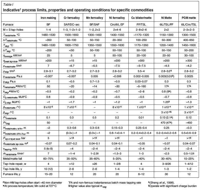