


Services on Demand
Article
 English (pdf)
 Article in xml format
 Article references
Indicators

Related links
-
 Cited by Google
 -
 Similars in Google
Share

 Permalink
Journal of the Southern African Institute of Mining and Metallurgy
On-line version ISSN 2411-9717
Print version ISSN 2225-6253
J. S. Afr. Inst. Min. Metall. vol.116 n.5 Johannesburg May. 2016
http://dx.doi.org/10.17159/2411-9717/2016/v116n5a7
PAPERS OF GENARAL INTEREST
A modified model to calculate the size of the crushed zone around a blast-hole
W. Lu; Z. Leng; M. Chen; P. Yan; Y. Hu
Wuhan University, Wuhan, China
SYNOPSIS
After detonation of the explosive, the final blast-induced damage area around the blast-hole falls into three categories, namely crushed zone, fractured zone, and elastic deformation zone. This paper presents a modified model to calculate the size of crushed zone around a blast-hole in drill-and-blast, with the hoop compressive stress and cavity expansion effect taken into account. The material in the crushed zone was assumed to be a granular medium without cohesion, but with internal friction. On this basis, the formula for crushing zone radius was derived. The proposed approach was verified with tests reported in the literature and the simulated results from SPH-FEM coupled models. A full statistical analysis was also carried out, and the predicted values were found to be in better agreement with the test results compared with other models. A sensitivity analysis of the modified model showed that the size of the blast-induced damage area is mainly affected by the following factors: rock mass properties, in situ stress, and borehole pressure. In particular, the roles of borehole pressure and in situ stress are discussed. Finally, suggestions are made on how the size of the crushing zones can be decreased.
Keywords: drill and blast, crushed zone, modified model, hoop compressive stress, cavity expansion
Introduction
Over the past decades, drill-and-blast has become the most commonly used technology in rock excavation. It is well known that in rock mass fragmentation with explosives, the annular rocks around the blast-hole are converted into fines. The formation of these fines consumes a significant part of the energy of the detonation, which in general is ignored in the determination of the efficiency of detonation (Glatolenkov and Ivanov, 1992; Furtney et al., 2012). Many studies show that only 20-30% of the total explosive energy is effectively used in fragmenting the rock, and up to 50% of the energy generated by conventional charges is wasted in overcrushing of the crushed zone and the inner part of the fractured zone (Ouchterlony et al., 2004; Sanchidrian et al., 2007). How to control the crushed zone to enhance the effective utilization of explosive energy, reducing the unit explosive consumption and the engineering cost, is therefore of great significance.
One of the most important problems in the breakage of rock masses is to establish a calculation model of the crushed zone around a blast-hole. The actual process of fragmentation around the blast-hole in drilling and blasting is so complex that an exact mathematical description is almost impossible. Over the years, many scholars and engineers have researched this problem (Wang, 2005; Jimeno et al., 1995; Ouchterlony and Moser, 2012; Qian, 2009), and several models have been proposed for the estimation of the extent of crushed zones around a blast-hole. Table I lists the existing models for prediction of the size of crushed zone. There are notable discrepancies among these calculation models. In the model proposed by Il'yushin (1971), the material in the crushed zone is assumed to be incompressible granular medium with cohesion. However, Il'yushin's formula is applied to limestone, talc-chlorite, and concrete, and Vovk et al. (1973) noted that Il'yushin appeared to overestimate the size of crushed zone. On the other hand, in Il'yushin's formula derivation process, the gas adiabatic index in the process of blasting cavity expansion was taken as a constant, so the formula is not applicable to conditions of large decoupling ratios. Szuladzinski (1993) modelled the crushing and cracking around the blast-hole using transient dynamic analysis. In that model, the rocks around the blast-hole are regarded as elastic materials and the effective energy of the explosive is assumed to be roughly two-thirds that of the complete reaction, which gives no consideration to the effect of decoupling. Djordjevic (1999) developed the two-component model (TCM), with overlapping fine-coarse component distributions. Based on the Griffith failure criterion, this model is applicable only to brittle rocks.
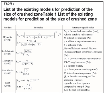
Kanchibotla et al. (1999) proposed an empirical model to determine the volume of fine material contributing to the run-of-mine blast fragmentation. Esen et al. (2003) reviewed different ways of calculating the size of crushed zone, introduced a dimensionless parameter called the crushing zone index (CZI), and developed their own formula particularly for smaller diameter holes and lower strength rock. Hagan and Gibson (1988) indicated that the borehole pressure will drop due to expansion of the blast-hole. The aforementioned models, except that of Il'yushin, do not consider the effect of cavity expansion on decreasing the borehole pressure. These previously proposed models have revealed some disadvantages related to the assumptions and the method used, and they cannot be applied to all types of rock masses and all charge structures. In particular, these models do not consider the effect of compressive hoop stress in the inner part of the fractured zone, as well as the in situ stress and the cavity expansion effect, which is of great important in the rock mass fragmentation process.
To explore the breakage mechanism of rocks around the blast-hole and to accurately predict the size of the crushed zone in drilling and blasting, a modified model for the size of the crushed zone is presented. The four-region model was established with hoop compressive stress in the inner part of fractured zone and cavity expansion effect taken into account. The material in the crushed zone is assumed to be a granular medium without cohesion, but with internal friction. The proposed approach was verified with tests reported in the literature and the simulated results from SPH-FEM coupled models. Also, the modified model is compared with a selection of existing models.
Distribution of rock fragmentation and assumptions for the modified model
Upon detonation of the explosive, the blast-hole wall is impacted by violent explosive shock waves, stress waves, and seismic waves successively, and the continuity of the rock medium changes, presenting different states of breakage and damage. The annular rock around the blast-hole will be crushed to a fine size. According to the degree of damage, the rock around the blast-hole wall can be divided into damage zones, the definition of which varies among scholars (Ghosh,1990). In previously proposed models, the final blast-induced damage area is usually divided into three categories, namely the crushed zone, radial crack zone, and elastic deformation zone (as shown in Figure 1).

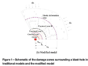
The existing models hold that the region between the crushed zone and elastic deformation zone is completely destroyed by the radial cracking, as shown in Figure 1a. In order to simplify the physical process, in those models, the rock between the crushed zone and elastic deformation zone can only transmit the radial stress, and cannot support any hoop stress, which means σe= 0. However, in the actual breakage process, since the fractured zone is a constraint that connects the crushed zone and the elastic zone, it cannot be completely destroyed by radial cracks. Meanwhile, the extent of damage of the rock medium in the inner part of fractured zone will be increased due to the hoop compressive stress. Regardless of hoop compressive stress, the calculated zone of damage will be larger than the actual.
The rock in the inner part of the fractured zone, which is subject to high radial compressive stress, is restrained by the surrounding rock due to the Poisson's effect. Therefore, it is essential to take the hoop compressive stress into account in this zone when establishing the calculation model. The fractured zone is therefore divided into two parts in this four-region model: the inner part (fractured zone I) and the outer part (fractured zone II), as shown in Figure 1b. In fractured zone I, the material is subject to plastic failure, and the hoop compressive stress is not zero, while in fractured zone II there is no hoop stress as a consequence of the damage caused by radial cracks. The four-region model is established with σθ≠ 0 in fractured zone I. The material in the crushed zone is assumed to be an incompressible granular medium without cohesion, and there is still internal friction among particles.
As a result, the modified model in this paper can better reflect the actual breakage mechanism of rocks around the blast-hole.
In this four-region model, the boundaries of the drilling and blasting damage zones are determined as follows:
(1) The crushed zone a(t) < r < b*(t)
(2) The fractured zone I b*(t) < r <<bI(t)
(3) The fractured zone II bI(t) < r < bII(t)
(4) The elastic deformation zone bII(t) < r < ∞
where a(t) is the radius of the expanding cavity (mm), b*(t) is the radius of crushed zone (mm), bI(t) is the radius of fractured zone I (mm), and bII(t) is the radius of fractured zone II (mm).
Supposing that there is a cylindrical cavity charged with explosives in a homogeneous and isotropic rock mass. An impulsive load will be loaded on the cavity wall when the explosives are detonated. In order to simplify the problem, some assumptions are made. The cylindrical cavity extends infinitely along the axis. Thus, the problem for cylindrical charge blasting can be simplified into an axial symmetric problem and a plane strain problem. The expansion of the detonation gas is adiabatic, and the volume of the detonation gas that infiltrates the rock cracks can be ignored.
Formula derivation
The elastic deformation zone
Using a cylindrical coordinate system to describe the problem, the stress distribution in the elastic deformation zone can be written as
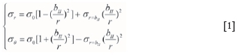
where stresses are assumed to be positive in compression, σr= bIIis the radial stress acting on the boundaries with the fractured zone II and with the elastic deformation zone, and σ0is the in situ stress in rock masses (Pa).
At the interface of the fractured zone II and the elastic deformation zone, the hoop stress reaches the tensile strength of the rock, which is σB=-[σt], thus or= bII= [σt]+2σ0according to Equation [1].
The radial displacement in the elastic deformation zone is
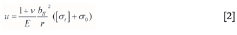
where E is Young's modulus (Pa), and v is Poisson's ratio.
Fractured zone II
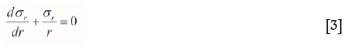
The material in fractured zone II is destroyed by radial cracks; as a result, it cannot support any hoop stress. However, the materials in the radial direction of fractured zone II are still elastic, similar to radial column bars, which can only pass the radial stress from fractured zone I to the elastic deformation zone. So in fractured zone II the condition σθ= 0 applies, then in axial symmetry, in a cylindrical system of coordinates (r, 0), the equilibrium equation reduces to:
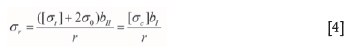
On the outer boundary of fractured zone II, σr= [σt]+2σ0, and on the inter boundary σr =[σc], where [σc] is the unconfined compressive strength (Pa).
Integrating the two, the radial stress distribution in the fractured zone II is found to be
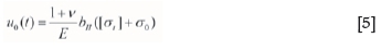
According to Equation [2] the displacement in the outer boundary of fractured zone II (when r= bII) is
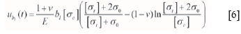
The displacement in the interboundary of the fractured zone II (when r= bI) is
Fractured zone I
The material in fractured zone I is subject to plastic failure, which results in a large number of cracks, leading to the expansion of the volume of the medium. It is therefore necessary to consider the rock dilatancy effect in this region. In fractured zone I, according to the plastic increment constitutive theory:
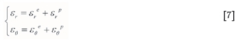
where εris total radial strain, εθ is total tangential strain, εrpis radial plastic strain, εreis radial elastic strain, εθp is tangential plastic strain, and εθe is tangential elastic strain.
The non-associated flow rule is used to describe the dilatancy characteristics of rock in fractured zone I.
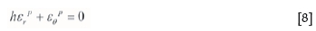
where h is the dilatancy ratio of the rock mass in fractured zone I. The dilatancy ratio describes rock's propensity to expand in volume after failure, and it is used mainly to control the compensation space in blasting. The dilatancy ratio of soft rock generally is 1.20-1.30, for medium hard rock 1.30 1.50, and for hard rock 1.50 2.50.
Substituting Equation [7] with Equation [8], so that

that is
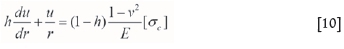
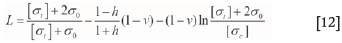
whence the displacement in the fractured zone I is given by:
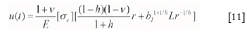
In order to describe the derivation process as simply as possible, let
In fractured zone I, a strength condition is fulfilled, taken in this work in the form of the Mohr-Coulomb condition
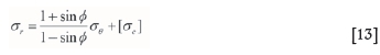
where φ is the angle of internal friction.
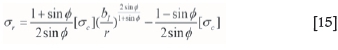
Substituting Equation [13] with the equilibrium Equation [14]:
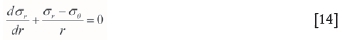
then the radial stress in the fractured zone I:
The crushed zone
After the detonation of the charge, the blast-hole is filled with gaseous detonation products at a very high temperature. A thin zone is formed around the blast-hole in which the rock mass has been extensively broken and crushed by high pressure (compressive and shear stress) that is exerted immediately on the blast-hole wall. The fine crushed material cannot support any shear in the absence of pressure, thus the cohesive strength is taken to be zero. The material in the crushed zone is assumed to be an incompressible granular medium without cohesion, and there is still internal friction among particles. A Mohr-Coulomb type model without cohesive strength is employed to define the material behaviour
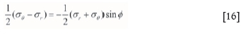
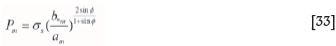
In the outer boundary of the crushed zone σr= σs, where, σSis compressive strength of the rock under multiaxial stress (Pa) (Rakishev and Rakisheva, 2011):
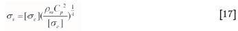
where ρmis the density of rock (g/mm3) and Cp is the velocity of elastic longitudinal waves in the rock mass (m/s).
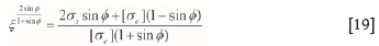
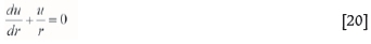
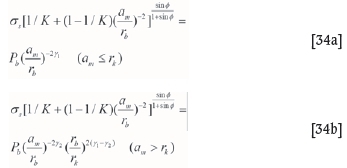
Substituting Equation [16] with the equilibrium differential (Equation [14] and integrating yields
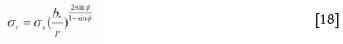
Due to the continuity requirement, the radial stress acting on the boundary must be the same on both sides. From Equation [14] and Equation [18] it is apparent that bI= ξb*, meeting the conditions
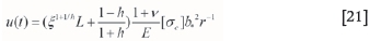
The incompressible condition is fulfilled in the crushed zone:
and integrating yields the radial displacement in the crushed zone:
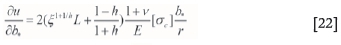
Differentiating u(t) with respect to b*(t) yields
On the condition that  the following approximate relationship holds:
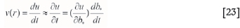
where v(r) is the velocity of particle in crushed zone (m/s).
On the expansion cavity wall (r= a(t)), the following equation holds:
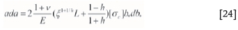
At initial time t = 0 the crushed zone begins generating at the cavity wall, hence a = b* = rb. Integrating yields
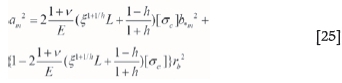
where b*m is the final radius of the crushed zone (mm) and amis the maximum cavity radius (mm). Letting
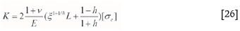
Equation [25] can be simplified to
Initially, the cavity is filled with gases with pressure Pb as a result of the explosion. There will be an increase in the blast-hole radius with an accompanying increase in the blast-hole volume and a drop in gas pressure. Gas pressure in the process of gas expansion in the explosion cavity can be calculated from the modified two-stages Jones-Miller adiabatic equation (Henrych, 1979) in the following form:
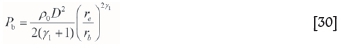
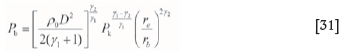
where Pb is the initial borehole pressure before expansion of the explosive (Pa), which is determined by the type of explosive and charge structure; Pm is the pressure at maximum cavity (Pa); the adiabatic isentropic exponents in two stages are γ1=3 and γ2=1.27, respectively; Pk is the critical pressure of explosion gases; and rkis the critical radius of explosion cavity corresponding to Pk,

According to the Chapman-Jouguet model for the detonation wave of condensed explosive, for a coupled charge, the initial explosion pressure Pb which denotes the gas pressure applied to the blast-hole wall is expressed by the widely known equation (Hustrulid 1999):
For a decoupled charge, if the decoupling coefficient is small, the initial explosion pressure Pb involved is:
where ρ0 is the explosive density (g/mm3), re is the charge radius (mm), and rb is the blast-hole radius (mm).
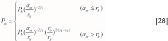
If the decoupling coefficient is large, the explosion pressure decreases from > Pkabove it to < Pk, where Pkis the critical gas pressure. In the calculation, the value of γ1is 3.0 when P > Pk, while γ2 is 1.27 when P < Pk. So Equation [30] is rearranged to yield the following expression for the explosion pressure:
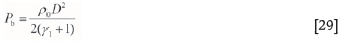
The critical pressure of explosion gases Pkis given by following equation (Henrych 1979):
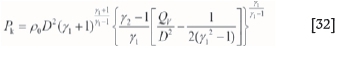
where ρ0 is the density of the explosive (g/mm3), D is the detonation velocity (m/s), and Qv is the reaction heat of the explosive (Nmm/g).
The pressure at the wall of the maximum cavity (r=am) is Pm= σr, according to Equation [18]
Rearranging Equations [27], [28], and [33] yields
From Equation [34] the ratios between maximum cavity radius and blast-hole radius (am/rb) can be obtained. Substituting (am/rb) into Equation [27] yields the ratios between the crushed zone radius and blast-hole radius (b*m/rb).
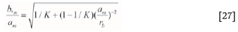
On the condition that the cavity expansion is noticeable, the approximate equation:

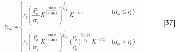
holds, and then Equation [27] can be simplified as:

According to Equations [34] and [36], the radius of the crushed zone around the blast-hole in column charge blasting becomes:
Comparison with existing models
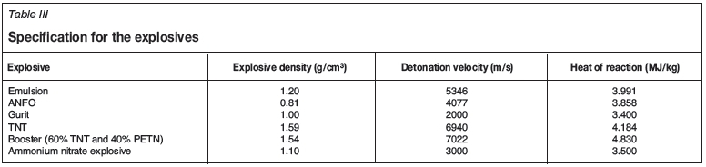
The physical and mechanical properties of four types of rocks chosen for the calculation are summarized in Table II. Explosives used in the calculation are ANFO, emulsion explosive, Gurit explosive, and booster and ammonium nitrate explosive. The properties of the commercial explosives used in the calculation and experimental work are summarized in Table III.
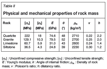
Table IV shows the ratios between the crushed zone radius and the blast-hole radius in different calculation models for different rock types and different explosive types. In general, for a specific rock and charge structure, the crushed zone radius increases as the blast-hole radius increases. Similarly, the models show that the explosive with higher density and higher detonation velocity has the potential to create a larger crushed zone for the same blast-hole radius and rock type. There are notable discrepancies between those calculation models. However, for a specific borehole pressure, the size of the crushed zone differs considerably between rock types; for example, the size of the crushed zone in high-strength rock types is no more than twice the radius of the blast-hole, while it can reach 3-5 times the blast-hole radius and more in low-strength rock types. The assessments of the size of crushed zone are conflicting, but most scholars hold that the size of the crushed zone does not exceed 3-5 times the blast-hole radius (Yang, 1991; Saharan et al., 1995), which is in agreement with the ranges calculated in the modified model.
According to the results calculated by the modified model, the thickness of the crushed zone increases with borehole pressure and the coupling between the charge and the blast-hole wall. The size of crushed zone is normally between 1.2 and 4.0 times the blast-hole radius with a fully coupled charge. Although this area is small, it consumes a considerable part of the explosive energy. Cook (1958) and Hagan (1977) hold that this mechanism consumes no less than 27% of the available strain wave energy, but makes only a very small contribution to the actual rock fragmentation, and around 0.1% of the total volume corresponding to the normal breakage per blast-hole (Jimeno et al., 1995). In addition, an increased amount of dust will be formed. Furthermore, the entry of gases into cracks can be easily hindered by the powdery materials within the crushed zone, which inhibits the 'gas wedge' effect, thus reducing the volume of rock breakage (Hagan and Gibson, 1998; Roy, 2005). Meanwhile, the high specific surface area of the particles within the crushed zone will absorb a large amount of heat from the gases, reducing the effective utilization of explosive energy.
Calculation results listed in Table IV for four types of rock indicate that there are notable discrepancies between different models. The analysis shows that the calculation results of the modified model are close to Esen's and Szuladzinski's results, while the models proposed by Il'yushin and Kanchibotla may overestimate the radius of the crushed zone. One of the reasons for the significant discrepancies is the different definitions of the crushed zone; for example, Il'yushin and Kanchibotla's models consider fractured zone I, where plastic failure occurs and fractures present mesh distribution, also as part of the crushed zone.
Comparison with experimental data
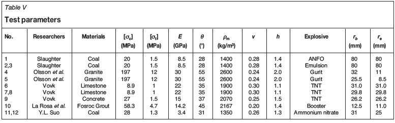
The blast-hole is fragmented and displaced after the detonation, so it is difficult to measure the radius of the crushed zone directly in a full-scale production environment. Single blast-hole blasting experiments are highly expensive and inconvenient, and related experiment data is therefore very scarce. Several drilling and blasting tests reported by other researchers have been used to validate this modified model's applicability to full-scale blasting. This paper collects four sets of data from blasting tests in limestone and concrete by Vovk (1973), one set from decoupling charge drilling blasting tests in granite by Olsson and Bergqvist, 1996 and Olsson et al., 2005), three sets from blasting tests in a coal mine by Slaughter (1991), one set from blasting tests in fosroc grout by La Rosa and Onederra (2001), and two sets of data from blasting tests in hard top-coal at the No.1 Honghui Mine by Suo (2004). Detailed test parameters are given in Table V.
Two drilling and blasting experiments were conducted by La Rosa and Onederra (2001) to measure the size of the crushed zone from a decoupled charge, as shown in Figure 2. The charge configuration consisted of a 25 mm blast-hole charged with a 22 mm UEE booster composed of 60% TNT and 40% PETN (see Table III). In each test, sections of the test samples were cut to reveal the size of the crushing zone. Figure 3 shows a comparison of different models in blasting experiments under corresponding conditions. The predictions of the crushed zone radius by the modified model are compared with the experimental data, and it is found that the predicted values are in better agreement with the test results than those from other models.
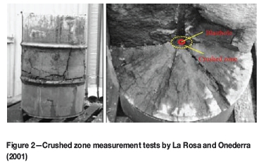
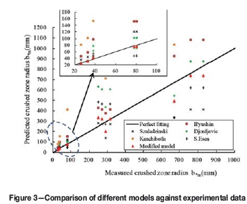
According to La Rosa and Onederra (2001), the crushed zone radii for both experiments were measured as 37.5 mm, i.e. three times the radius of the blast-hole. As shown in Figure 3, the ratios of the crushed zone radius and the blast-hole radius (b*m/rb) calculated by the models proposed by Il'yushin, Djordjevic, and Kanchibotla under specific conditions are 7.85 6.25, and 12.30, respectively. However, the ratio calculated by the modified model is 3.38, thus the predicted values by this modified model agree reasonably well with the experiments results of La Rosa and Onederra.
Several performance indices, including coefficient of determination R2 and root mean square error (RMSE) were computed to evaluate the performance of the predictive models:
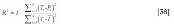
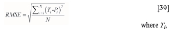
Piand  are the measured, predicted from tests, and mean of the Ti values (mm), respectively, and N is the total number of data. Theoretically, the model will be excellent if R2 is unity and RMSE is zero.
Results of performance indices (R2, RMSE) for predictions and testing data-sets of different models are tabulated in Table VI. As it can be seen, the performance indices show that the modified model can predict the size of crushed zone with higher degree of accuracy compared to other models.
Since the size of the crushed zone in Szuladzinski's model is only a function of explosive density, effective energy of the explosive, and the dynamic compressive strength of the rock material, it is unsuitable for the decoupling cases. Also, the models proposed by Il'yushin and Kanchibotla seem to overestimate the size of the crushed zone under the condition of decoupling charge. The methods proposed by Esen and the modified model take an effective account of the effect of decoupling on the extent of crushing.
Comparison with numerical simulation results
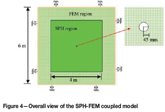
A coupled numerical approach with combined smooth particle hydrodynamics (SPH) and FEM methods was also conducted to investigate the effects of single blast-hole. The SPH method, which is Lagrangian and mesh-free, it is well suited to analyse large deformation events involving failure and fragmentation (Hu et al., 2015). However, the SPH method has some difficult in applying boundary conditions and its calculation efficiency becomes a bottleneck for applying this method to engineering practice. Therefore, the combination of SPH and FEM is a good solution to accurately simulate the whole process of rock blasting. The SPH technique is employed to model the explosive charge and the close-in zones where a large amount of deformation takes place, while the normal FEM is used in the far field. One can make full use of the FEM method to apply boundary conditions for the model, thus guaranteeing the calculation accuracy as well as calculation efficiency.
A two-dimensional numerical model was developed with a combined SPH-FEM approach to simulate the blast-induced damage around a single blast-hole in granite and limestone, as illustrated in Figure 5. The RHT model, developed by Riedel, Hiermaier, and Thoma (1999), is adopted in the present study. The JWL equation of state models the pressure generated by the expansion of the detonation products of the chemical explosive (Yang et al., 2015). The numerical parameters for the rock and explosive are adopted from Table II and Table III.
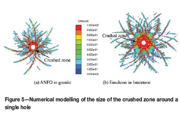
According the simulated results in Figure 5, the ratios of the crushed zone radius and the blast-hole radius (b*m/rb) calculated by the numerical models are 1.75 and 3.16, while the values calculated by our modified model are 1.58 and 2.77.Although the radii of the crushed zones in both granite and limestone obtained from this modified model are a little smaller than that of numerical model, the numerical simulation results and modified model results agree well. As far as the crushed zones are concerned, it can be said that the results obtained from this modified model give a good prediction for the blast-induced crushed zone.
Factors influencing the crushed zone
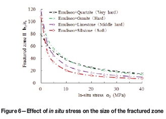
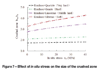
The modified model shows that the crushed zone radius is affected mainly by the rock mass properties, in situ stress σ0, borehole pressure Pb, and blast-hole radius rb. In particular, the roles of borehole pressure and in situ stress are discussed. The sizes of the crushed zone in different types of rock under different borehole pressure and in situ stress are compared. The blasting load mainly induces tensile damage (the fractured zone) to the surrounding rock. Since this tensile effect is very easily inhibited by the in situ stress, the fractured zone is significantly reduced with increasing in situ stress, as shown in Figure 6. However, it has been found that the in situ stress apparently has a slight effect on the size of crushed zone, especially in hard rock. The size of the crushed zone increases slowly with the in situ stress, and such increase is more noticeable in soft rock, as shown in Figure 7. It can be predicted that for drilling and blasting in deep underground caverns, when the in situ stress reaches a higher level, the tension effect may be completely inhibited, and there would be a crushed area only around the blast-hole.
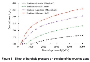
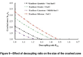
As shown in Figure 8, the size of the crushed zone decreases significantly as the borehole pressure falls. Reducing the borehole pressure Pb is therefore an effective way to reduce the size of the crushed zone. Borehole pressure Pb is related to explosive characteristics and charging structure, so one can reduce the crushed zone by adjusting explosive characteristics or improving charging structure, such as by using lower energy explosives, or using a decoupling or air-decked charge. When using the decoupling charging structure, the size of the crushed zone decreases quickly along with the increase in decoupling ratio, as shown in Figure 9. There is even no fine crushing if the decoupling ratio increases to a certain value.
Conclusions
A modified model to calculate the size of the crushed zone around the blast-hole has been presented that takes into account the hoop compressive stress in the inner part of fractured zone and cavity expansion on decreasing the borehole pressure. As a result, the modified model can better reflect the actual breakage mechanism of rocks around the blast-hole. The proposed approach has been verified with tests reported in the literature as well as simulated results from SPH-FEM coupled models. Compared with other models, the calculation results from this model are in better agreement with the test results.
The crushed zone radius formula derived from the modified model indicates that the size of the crushed zone is related to the rock properties, the characteristics of the explosives, the charge structure, and the blast-hole radius. The analysis shows that there are notable discrepancies between rock types, and usually the size of the crushed zone ranges from 1.2 to 5.0 times the blast-hole radius.
The in situ stress apparently has a slight effect on the size of the crushed zone, especially in hard rock. The size of the crushed zone increases slowly with the in situ stress, with the increase being more noticeable in soft rock. However, the tensile fracture effect is very easily inhibited by the in situ stress, and the size of the fractured zone is significantly reduced with increasing in situ stress. One of the prime reasons for overcrushing is unacceptable levels of borehole pressure in blasting. It is found that reducing the borehole pressure Pbis an effective way to reduce the size of the crushed zone. The size of the crushed zone decreases significantly along with the increase of decoupling ratio. The crushed zone can be reduced by using a decoupling charging structure.
Acknowledgements
This work was supported by Chinese National Programs for Fundamental Research and Development (973 Program) (2011CB013501), Chinese National Natural Science Foundation (51125037 and 51279135), and the Doctoral Scientific Fund Project of the Ministry of Education of China (20110141110026). The authors wish to express their thanks to all the supporters.
References
Djordjevic, N. 1999. A two-component of blast fragmentation. Proceedings of the Sixth International Symposium on Rock Fragmentation by Blasting (Fragblast-6), Johannesburg, South Africa, 8-12 August 1999. Southern African Institute of Mining and Metallurgy, Johannesburg. pp. 213-222. [ Links ]
Esen, S., Onederra, I., and Bilgin, H.A. 2003. Modelling the size of the crushed zone around a blasthole. International Journal of Rock Mechanics and Mining Sciences, vol. 40, no. 4. pp. 485-495. [ Links ]
Furtney, J.K., Sellers, E., and Onederra, I. 2012. Simple models for the complex process of rock blasting. Proceedings of the 10th International Symposium on Rock Fragmentation by Blasting, New Delhi, India. pp. 275-282. [ Links ]
Ghosh, A. 1990. Fractal and numerical models of explosive rock fragmentation. university of Arizona. [ Links ]
Glatolenkov, A.I. and Ivanov, V.I. 1992. Mechanism of breakdown of rock masses and formation of fines by blasting. Journal of Mining Science, vol. 27, no. 5. pp. 444-452. [ Links ]
Hagan, T.N. and Gibson, I.M. 1988. Lower borehole pressures: a means of reducing costs when blasting rocks of low to moderate strength. International Journal of Mining and Geological Engineering, vol. 6, no. 1. pp. 1-13. [ Links ]
Henrych, J. 1979. The Dynamics of Explosion and Its Use. Elsevier, Amsterdam. [ Links ]
Hu, Y.G., Lu, W.B., Chen, M., Yan, P., and Zhang, Y.Z. 2015. Numerical simulation of the complete rock blasting response by SPH-DAM-FEM approach. Simulation Modelling Practice and Theory, vol. 56. pp. 55-68. [ Links ]
II'yushin, A.A. 1971. The mechanics of a continuous medium. Izd-vo MGU, Moscow (in Russian). Translated in: 1999. Blasting Principles for Open Pit Blasting, Hustrulid, W. (ed.). Balkema, Brookfield. [ Links ]
Jimeno, E.L., Jimino, C.L., and Carcedo, A. 1995. Drilling and Blasting of Rocks, CRC Press. [ Links ]
Kanchibotla, S.S., Valéry, W., and Morrell, S. 1999. Modelling fines in blast fragmentation and its impact on crushing and grinding. Proceedings of Explo'99, Kalgoorlie, Western Australia, 7-11 November 1999. pp. 137-181. [ Links ]
La Rosa, D. and Onederra, I. 2001. Acceleration measurements from a small diameter explosive charge. Confidential Internal Report. JKMRC, Brisbane, Australia. [ Links ]
Olsson, M. and Bergqvist, I. 1996. Crack lengths from explosives in multiple hole blasting. Proceedings of the Fifth International Symposium on Rock Fragmentation by Blasting, Montreal, Quebec, Canada. Balkema, Rotterdam. pp. 187-191. [ Links ]
Olsson, M., Nie, S., Bergqvist, I., and Ouchterlony, F. 2002. What causes cracks in rock blasting? Fragblast: International Journal for Blasting and Fragmentation, vol. 6, no. 2. pp. 221-233. [ Links ]
Ouchterlony, F. and Moser, P. 2012. On the branching-merging mechanism during dynamic crack growth as a major source of fines in rock blasting. Proceedings of the 10th International Symposium on Rock Fragmentation by Blasting, New Delhi, India. CRC Press, Leiden, The Netherlands. pp. 65-75. [ Links ]
Ouchterlony, F., Nyberg, U., Olsson, M., Bergqvist, I., Granlund, L., and Grind, H. 2004. Where does the explosive energy in rock blasting rounds go?. Science and Technology of Energetic Materials. vol. 65, no. 2. pp. 54-63. [ Links ]
Qian, Q.H. 2009. Some advances in rock blasting dynamics. Chinese Journal of Rock Mechanics and Engineering, vol. 28, no. 10. pp. 1945-1968. [ Links ]
Rakishev, B. and Rakisheva, Z.B. 2011. Basic characteristics of the stages of rock mass if destruction by explosive crushing. Proceedings of the Asia-Pacific Symposium on Blasting Techniques, KunMing, China. pp. 65-69. [ Links ]
Riedel, W., Thoma, K., and Hiermaier, S. 1999. Numerical analysis using a new macroscopic concrete model for hydrocodes. Proceedings of the 9 th International Symposium on Interaction of the Effects of Munitions with Structures, Berlin, Germany. pp. 315-322. [ Links ]
Roy, P.P. 2005. Rock Blasting: Effects and Operations. CRC Press. [ Links ]
Saharan, M.R., Mitri, H.S., and Jethwa, J.L. 2006. Rock fracturing by explosive energy: review of state-of-the-art. Fragblast: International Journal for Blasting and Fragmentation, vol. 10, no. 1-2. pp. 61-81. [ Links ]
Sanchidrian, J.A., Segarra, P., and Lopez, L.M. 2007. Energy components in rock blasting. International Journal of Rock Mechanics and Mining Sciences, vol. 44, no. 1. pp.130-147. [ Links ]
Slaughter, S. 1991. Investigation of coal fines. Internal Report, JKMRC, Australia. [ Links ]
Suo, Y.L. 2004. Distribution characteristic of breaking extending area of weakening-blast in hard top-coal. Journal of China Coal Society, vol. 29, no. 6. pp. 650-654. [ Links ]
Szuladzinski, G. 1993. Response of rock medium to explosive borehole pressure. Proceedings of the Fourth International Symposium on Rock Fragmentation by Blasting (Fragblast-4), Vienna, Austria, 5-8 July 1993. Rossmanith, H-P. (ed.). Balkema, Rotterdam. pp. 17-23. [ Links ]
Vovk, A., Mikhalyuk, A., and Belinskii, I. 1973. Development of fracture zones in rocks during camouflet blasting. Soviet Mining Science, vol. 9, no. 4. pp. 383-392. [ Links ]
Yang, S.Y. 1991. Foundations of Dynamics in Rock Blasting. China Coal Industry Publishing House, Beijing. [ Links ]
Yang, J.H., Lu, W.B., Hu, Y.G., Chen, M., and Yan, P. 2015. Numerical simulation of rock mass damage evolution during deep-buried tunnel excavation by drill and blast. Rock Mechanics and Rock Engineering, vol. 48, no. 5. pp. 2045-2059. [ Links ]
Wang, M.Y., Deng, H.J., and Qian, Q.H. 2005. Study on problems of near cavity of penetration and explosion in rock. Chinese Journal of Rock Mechanics and Engineering, vol. 24, no. 16. pp. 2859-2863. [ Links ]
Paper received Oct. 2014
Revised paper received Sep. 2015.
© The Southern African Institute of Mining and Metallurgy, 2016. ISSN 2225-6253.

