


Servicios Personalizados
Articulo
 Inglés (pdf)
 Articulo en XML
 Referencias del artículo
Indicadores

Links relacionados
-
 Citado por Google
 -
 Similares en Google
Compartir

 Permalink
Journal of the Southern African Institute of Mining and Metallurgy
versión On-line ISSN 2411-9717
versión impresa ISSN 2225-6253
J. S. Afr. Inst. Min. Metall. vol.116 no.4 Johannesburg abr. 2016
http://dx.doi.org/10.17159/2411-9717/2016/v116n4a8
STUDENT EDITION - METALLURGY
An evaluation of the thermal fatigue performance of three alloys for casting mould applications
V. van der Merwe; C.W. Siyasiya
University of Pretoria, Department of Materials Science and Metallurgical Engineering, Pretoria, South Africa
SYNOPSIS
A petrochemical company experiences premature thermal fatigue failure of the casting moulds used in catalyst production. The aim of the project was to find an alternative alloy that would outperform the current low-alloy cast steel used for the moulds. Based on their thermo-fatigue properties, 3CR12 ferritic stainless steel and H11 tool steel were chosen for testing and comparison with the currently used BS3100 B7 cast steel. Samples of each material were subjected to temperature cycling in a Gleeble 1500TM thermo-mechanical processing simulator, followed by surface analyses. The main parameters derived from the test work were the total true strain, the hot strength of the materials, and the number of cycles to failure. Additionally, the coefficient of thermal expansion for each material was measured using a Bähr dilatometer. H11 tool steel yielded the best performance by way of having the fewest surface cracks, the lowest total true strain per cycle, the most cycles to failure, the highest hot strength, and the lowest coefficient of thermal expansion.
Keywords: thermal fatigue, fatigue failure, casting moulds, thermal expansion
Introduction
The Catalyst Manufacturing Plant (CMP) is a dusty environment with temperatures higher than ambient. Molten mill scale (magnetite, Fe3O4) is tapped from the electric arc furnace into the casting moulds at temperatures close to 1600°C. After 10 seconds the magnetite is quenched with a water spray for 50 seconds to a minimum temperature of 400°C. Sometimes there is residual water in the pans from the cooling fog process (water sprays) in the empty mould. In a typical plant, the factory produces 40-44 batches a day containing between 150-300 moulds, depending on the time required for the specific batch (Buchholz, 2014). The typical batch in the CMP usually weighs about 6 t. The thickness of the tap, speed of the casting belt, and tilting angle all affect the number of moulds per batch.
One of the main problems faced during the molten mill scale casting is the premature failure of the casting moulds. Cracks initiate on the surface of the mould, which is in contact with the hot catalyst, and propagate into the interior of the mould. Cracks are generally concentrated in the middle area of the mould where the catalyst makes first contact with the mould, and which experiences the highest temperature fluctuations. This suggests that the cracks are caused by thermal fatigue during the casting process.
In order to prolong the life of the mould and improve the operational efficiency, a recommendation for a new alloy or an improvement of the existing casting mould had to be made.
In many instances, there are no service life records for specific moulds to track their life span, as well as no records regarding the surface temperatures of the mould during the heating and cooling cycle. The operating conditions and safety concerns make it impossible to measure the surface temperatures. Therefore, the temperature fluctuations can only be estimated.
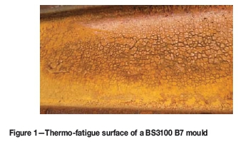
On average, the casting moulds last about 6 months in this operating environment. One of the primary indications that the mould has reached the end of its life is the sticking of the catalyst to the mould due to the enlarged surface area caused by the surface cracks, as seen in Figure 1. This type of surface is called the 'elephant skin' and is caused by thermal fatigue.
Thermal fatigue failure
All materials of construction are affected by thermal fatigue. This is a result of cyclic stresses caused by variations in temperature. The damage occurs under repeated thermal cycling in the form of cracking in the metal, specifically where relative movement (differential expansion) is constrained (American Petroleum Institute, 2011).
The failure of the moulds in the current investigation can be classified as a low-cycle high-strain fatigue problem, typically with N < 104 cycles. The number of cycles to failure is fewer that in typical high-frequency low-cycle fatigue. In these casting moulds, the thermal fatigue failure is controlled by a cyclic plastic strain rather than a cyclic stress. The cyclic plastic strain results from the thermal stresses, which are a consequence of the temperature fluctuations during the casting process. The number of cycles to failure, Nf, for this type of fatigue failure can be predicted by the Coffin-Manson equation.
This approach is similar to what is known as the Paris equation for the stable crack growth regime. The Paris equation for high-frequency low-cycle fatigue is
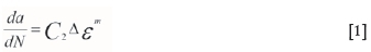
where
C2 = Constant
Δε = Cyclic strain amplitude.
Low-cycle fatigue test data are often represented as a plot of the plastic strain range versus cycles to failure. When plotted on log-log coordinates, a straight line is obtained, which is represented by the Coffin-Manson relation:
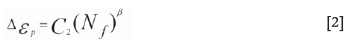
where Δερis the plastic strain range, Nfis the number of cycles to failure (fatigue life), C2 is a constant and β is the fatigue ductility exponent (generally -0.5 > β < -0.7) (Coffin Jr., L.F., 1954; Manson, S.S., 1954)
Experimental procedure
The physical properties of the three steels that were investigated are given in Table I. The selection of 3CR12 and H11 steels was based on their melting points, coefficients of thermal expansion, and thermal conductivities. The chemical compositions of the steels are given in Tables II.
The thermal fatigue simulation was carried out in a Gleeble 1500TM thermo-mechanical processing simulator. This apparatus enables the specimen to be subjected to either isothermal compression or tensile tests at elevated temperature. However, in this investigation, the specimens were subjected to temperature cycling without constraint.
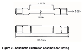
Three samples, 10 mm in diameter and 116.5 mm in length, were prepared of each material (Figure 2). The test zone at the centre of each sample was milled to a thickness of 7 mm for entire gauge length of 50 mm so as to create sharp corners simulating the edges of the mould. Two K-type thermocouples were spot-welded onto each specimen: one in the middle and one further away from the centre of the specimen, to measure the temperature. Each test was run for 100 cycles over approximately 3 hours. In a case where the cracks appeared before 100 cycles were completed, the experiment was stopped prematurely. The temperature was fluctuated between 400 and 1200°C. In the first 50 seconds, the specimen was heated to 1200°C at a heating rate of 20°C/s, followed by another 10 seconds of soaking at the elevated temperature. The specimen was then cooled to 400°C at a cooling rate of 20°C/s. This cycle was repeated 100 times.
After completion of the test, the surface of each specimen was examined for cracks or other irregularities. Photographs of the surface were taken, before and after cleaning with Hibatex solution to remove oxides, using a stereo microscope at magnifications of 12x and 15x. The data generated was used to calculate the total plastic strain in 100 cycles. Three tests were conducted for each steel, and an average value for the total plastic strain after 100 cycles was obtained. Equation 3 was used to calculate the total plastic strain, ε, after 100 cycles.
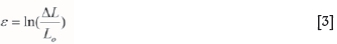
where ΔL is the change in length (m) and L0is the gauge length of the specimen (m).
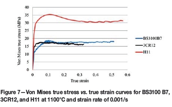
The hot strength of the steels was determined at 1100°C through an isothermal hot compression test, see Figure 7. The strain was limited to 0.8 to avoid barrelling effects.
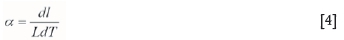
The coefficient of thermal expansion was determined using the Bahr dilatometer. This test was done in accordance with ASTM E831-14 specifications. The thermal expansion coefficient α is a material constant. It is the amount of expansion or contraction a material undergoes per kelvin during heating or cooling and is given by the following equation:
where
dL = Change in length (μm)
dT = Change in temperature respectively (°K)
L = Total length of the specimen (m)
a = Thermal expansion coefficient (μηι/m.°Κ)
The thermal expansion coefficient should be as low as possible when the material is used to make moulds used in the casting process.
The specimens were 5 mm in diameter and 10 mm long. Three of these specimens were machined for each alloy. The sample was heated to 1220°C (above AC3) at a heating rate of 0.25°C/s. The specimen was then soaked for 60 seconds and afterwards cooled to room temperature at a cooling rate equivalent to that of the heating rate. Lastly, Ac3 is the temperature at which ferrite completes its transformation to austenite during the heating up cycle.
Results and discussion
Surface evaluation
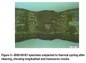
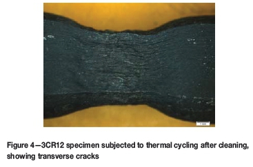
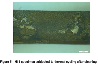
Figures 3, 4, and 5 show stereo micrographs for BS3100 B7, 3CR12, and H11 after 100 thermal cycles between 400 and 1200°C.
As expected, the surface of BS3100 B7 was heavily oxidized. After removing the oxides, cracks were exposed and were visible in the centre area in both longitudinal and transverse directions (Figure 3). 3CR12, in contrast, exhibited less oxidation than BS3100 B7. However, cracks were visible in the transverse direction in Figure 4. Strain marks (material flow lines) in the lengthwise direction were also present. No visible cracks or irregularities like strain markings or necking were observed in H11 (Figure 5). The specimen was still in sound condition after 100 cycles.
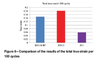
Figure 6 shows a summary of the total plastic strain for each steel after 100 thermal fatigue cycles. The total true plastic strain per 100 cycles for BS3100 B7, 3CR12, and H11 was 0.148, 0.182, and 0.058 respectively. The total plastic strain represents the measure of resistance to thermal fatigue.
Estimated number of cycles to failure (Nf)
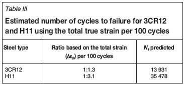
The average number of cycles to failure for BS3100 B7, based on the industrial data, is 11 340 i.e. Nf (BS3100B7) =11 340 cycles. The cycles to failure for 3CR12 and H11 are unknown. However, the ratios of the cycles to failure for BS3100 B7:3CR12 and BS3100 B7:H11 can be determined based on the total true strain per 100 cycles. The number of cycles to failure for 3CR12 and H11 can then be calculated by multiplying the respective ratios by Nf (BS3100B7). The results are shown in Table III.
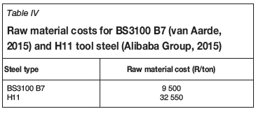
Although H11 tool steel looks promising, it is more expensive than BS3100 B7. Therefore, before H11 can be recommended as an alternative material, a comprehensive cost benefit analysis would be required. Based on a rough calculation regarding the raw material cost, the cost of H11 is 3.5 times higher than that of BS3100 B7 (Table IV).
Hot-strength: high-temperature steady-state stress
Figure 7 shows the Von Mises true stress versus true strain for the three steels. H11 exhibited the highest hot strength of 31 MPa. The hot strengths of 3CR12 and BS3100 B7 were lower than H11, and similar i.e. 16 and 18 MPa respectively.
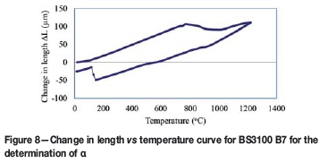
Coefficient of thermal expansion
Figure 8 shows a typical dilatometer-generated plot of change in length versus temperature. The α values for BS3100 B7, 3CR12, and H11 were found to be 15.8, 13.1, and 12.8 μm/ηι0Χ respectively.
Conclusions
The thermal fatigue behaviours of BS3100 B7, 3CR12, and H11 were compared under similar conditions.
H11 had the lowest total true strain of 0.058 per 100 cycles, indicating that it had the highest resistance to thermal fatigue compared with 3CR12 and BS3100 B7. The mould life would be longer than for the other two steels, and was estimated to be about 35 478 cycles.
However, before H11 tool steel can be recommended as an alternative material, a comprehensive cost analysis is required. Based on a rough calculation regarding the raw material cost, the cost of H11 is 3.5 times higher than that of BS3100 B7.
References
Alibaba Group. 2015. Minerals & Metallurgy.http://www.alibaba.com/showroom/alloy-raw-material-price-h11-tool-steel.html [Accesed 18 October 2015]. [ Links ]
American Petroleum Institute. 2011. API recommended practice 571: Damage mechanisms affecting fixed equipment in the refining industry. 2nd edn. API Publishing Services, Washington. [ Links ]
ASTM International. 1978. Metals Handbook: Properties and selection on irons steels. Benjamin, D. (ed.). Materials Park, OH. pp. 114-116. [ Links ]
ASTM International. 1980. Metals Handbook: Properties and selection on tool steels. Benjamin, D. (ed.). Materials Park, OH. [ Links ]
ASTM International. 2015. ASTM E831. Standard test method for linear thermal expansion of solid materials by thermomechanical analysis. Materials Park, oH. [ Links ]
AZO Materials. 2014. Investigation of fatigue crack propagation in polymers. http://www.azom.com/article.aspx?ArticleID=11114 [Accessed 17 March 2016]. [ Links ]
Buchholz, H. 2014. Catalyst Manufacturing Unit, Secunda. Personal communication and unpublished results. [ Links ]
Coffin Jr., L.F. (1954), A study of the effects of cyclic thermal stresses on a ductile metal, Trans. ASME, vol. 76, pp. 931-950. [ Links ]
Columbus Stainless. 2015. Unpublished results. Middelburg, South Africa. [ Links ]
Du Toit, W. 2015. Orion Engineering, Pretoria. Unpublished results. [ Links ]
Hertzberg, J.L. 2013. Deformation and Fracture Mechanics of Engineering Materials. 5th edn. Courier Westford, North Chelmsford, MA. [ Links ]
Manson, S.S. (1954), Behaviour of materials under conditions of thermal stress, NACA TN-2933, National Advisory Committee for Aeronautics [ Links ]
Stumpf, W. 2014. Department of Materials Science and Metallurgical Engineering, university of Pretoria. unpublished results. [ Links ]
Van Aarde, B. 2015. Steloy, Johannesburg. Personal communication. [ Links ]
Paper received Apr. 2016.
Paper written on project work carried out in partial fulfilment of B. Eng. (Metallurgical Engineering)

