


Services on Demand
Article
 English (pdf)
 Article in xml format
 Article references
Indicators

Related links
-
 Cited by Google
 -
 Similars in Google
Share

 Permalink
Journal of the Southern African Institute of Mining and Metallurgy
On-line version ISSN 2411-9717
Print version ISSN 2225-6253
J. S. Afr. Inst. Min. Metall. vol.116 n.4 Johannesburg Apr. 2016
http://dx.doi.org/10.17159/2411-9717/2016/v116n4a4
STUDENT EDITION - MINING
Review of support systems used in poor ground conditions in platinum room and pillar mining: A Zimbabwean case study
T. Chikande; T. Zvarivadza
School of Mining Engineering, University of the Witwatersrand, Johannesburg, South Africa
SYNOPSIS
Falls of ground pose costly hazards to personnel and equipment and thus measures should be taken to prevent them. This study endeavours to improve the support systems used in geotechnically poor ground at a Zimbabwean platinum mine by analysing the status quo and recommending an effective support system. Various techniques were used to determine the quality of ground conditions, predict the rock mass behaviour, and to identify the appropriate rockbolt type. An analysis of the current ground control methods and their limitations was also undertaken.
The results showed that the current support system and mining practices in poor ground need to be modified to improve safety and productivity. Stoping overbreak is influenced by poor ground conditions and the explosives currently used. The use of emulsion is recommended to replace ANFO. Redesigning of pillars is also recommended in poor ground conditions. An evaluation of the current roofbolt system indicated an opportunity for improvement. With new insight on the performance of the shorter length roofbolts currently in use, a new support system was recommended taking into consideration cost-benefit analysis. Barring down using pinch bars in poor ground was seen as a risky and time-consuming exercise, hence the use of mechanical scalers is recommended to achieve zero harm and to meet production targets. Smoothwall blasting is recommended in poor ground to minimize excavation damage. Other recommendations include the use of hydrological surveys to determine groundwater levels and implement corrective measures. Both empirical and numerical modelling approaches need to be utilized in determining the optimum support.
Keywords: bord and pillar mining, support systems, pillar design, explosives, roofbolts
Introduction
The presence of geological discontinuities such as faults and joints weakens the rock mass. Adequate support is critical in achieving zero harm in underground mines. This paper reviews the current support systems used in poor ground conditions at a Zimbabwean platinum mine. The area of research is located on the Great Dyke of Zimbabwe. The mine exploits platinum group elements (PGEs) and base metals. It is shallow, having a maximum depth of less than 300 m. The Great Dyke is the second largest reserve of PGEs, following the South African Bushveld Complex (Oberthür et al., 2012). It is a linear layered intrusion that extends for about 550 km with a maximum width of 11 km (Prendergast, 1989). The generalized section of the Great Dyke is almost like a trumpet, comprising layers that dip towards the centre. The reef exploited at the mine, the Mineralised Sulphide Zone (MSZ), is located in the pyroxenite layer, which is hosted in the ultramafic sequence. The MSZ is a uniform layer about 23.5 m thick, dipping at around 10-14° from surface outcrop towards the axis of the basin, and located between bronzite and websterite horizons. The visible disseminated sulphide mineralization shows a typical and consistent vertical distribution of platinum group metal (PGM) and base metal values. The research was undertaken to review the current support systems used in geotechnically poor ground conditions in a bid to improve both safety and productivity.
Mining method
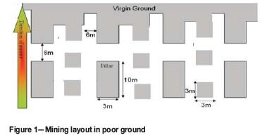
The mine is fully mechanized and uses the bord and pillar mining method. Access is via two declines, one for access of men and materials and the other for hoisting ore. The mining layout used in poor ground conditions is shown in Figure 1.
Mining environment
The area investigated is characterized by upthrows usually related to sympathetic faults and increased joint frequency. This imposes challenging mining conditions and increases the risk of rockfalls. The reef-subparallel planes in the hangingwall can give rise to unstable hangingwall environments, resulting in block and wedge failures when the planes of weakness are intersected by the J1 and J2 joint (discontinuity) sets. As the number of joint sets increases, the strength of the rock mass deteriorates. There are three prominent joint sets at the mine:
>J1, which trends east-west with an average dip of 70° and a strike of close to 90°
>J2, which trends north-south and has an average strike of 008°
>J3, which comprises a shallow-dipping plane parallel to sub-parallel to the orebody.
Talc and serpentine are the common types of joint infill material.
Project background
The company uses a mechanized room and pillar mining method. As mining progresses, the intensity of faulting and jointing increases. This has led to general support failure and a challenge in maintaining a stoping width of 2 m. Associated problems and consequences of this include stoping overbreak, grade dilution, unpredictable unravelling of rocks, a decreased factor of safety, increased support costs, and failure to meet production targets.
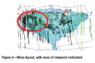
The problems and consequences of poor ground conditions led to the need to review the current support system at the mine. Figure 2 shows the mine layout and the area where the research was conducted.
The need to conduct the research is justified by the following:
>The obligation to improve safety by ensuring that there is adequate regional and local support
>The need to improve productivity by meeting production targets in the required time
>The need to minimize PGE grade dilution
>The need to minimize cost of re-supporting
>The opportunity to add value to the company.
Project objectives
The main objectives were to analyse and improve the current support systems used in poor ground. This was done by:
>Reviewing the current support system and identifying its limitations
>Designing an effective support system to be used in poor ground
>Making recommendations that can be used to improve the support systems.
Literature review
To effectively pin down the research problem and come up with effective solutions, a critical review of relevant literature was undertaken. Rock masses experience primitive stress before mining and induced stresses after openings are excavated. Virgin stresses exist in rocks prior to any excavations (Brady, 1985). The magnitude of the vertical component of virgin stress is given (Brady, 1985) by:

where ρ is the density of the rock mass, g is acceleration due to gravity, and h is the depth below the surface in metres.
Causes of instability
Wood (1987) pointed out that instability can be caused by the following:
>A decrease in strength to stress ratios, which results in failure of material around the excavation
>Geological structures that result in collapse
>A combination of the above two points
>Seismic events.
The authors investigated the strength to stress ratios in a bid to determine the factor of safety. There is no history of seismic events in the area of the investigation, hence seismic forces were ignored: however, the authors recommended that the mine install seismic monitoring devices.
Deere's Rock Quality Designation RQD
Brady (1985) noted that when there is no core available but there are traces of geological discontinuities, Equation [2] can be used to determine Rock Quality Designation (RQD).

where Jvis the sum of the number of joints per unit length for all discontinuity sets, and is known as the volumetric joint count.
RQD is a directionally dependent factor when determined using drill core. The use of volumetric joint count is of paramount importance in reducing this directional dependence (Brady, 1985). RQD is envisioned to indicate the quality of the in situ rock mass. The calculated RQD will then be used to determine the Q rating and Rock Mass Rating
(RMR).
Geomechanics classification I Rock Mass Rating (RMR)
The RMR system incorporates the sum of six parameters (Bieniawski, 1989):
1. Uniaxial compressive strength of rock material
2. Rock Quality Designation (RQD)
3. Spacing of discontinuities
4. Condition of discontinuities
5. Groundwater condition.
6. Orientation of discontinuities.
The relationship between RMR and Q is given by (Brown and Hoek, 1980):
RMR = 9ln Q + 44
Q system
Barton et al. (1974) noted that the Q system classification is based on the following three aspects:
>Block size (RQD/Jn)
>Inter-block shear strength Jr/Ja)
>Active stress Jw/SRF)
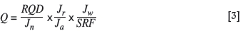
The authors used the Q system to estimate the required support based on charts, which are discussed under results.
Support systems
A sound strategy for overall mine stability is critical to avoid accidents or conditions that may give rise to incidents. The major hazards addressed by a sound mining method design and layout include uncontrolled collapses, surface subsidence, and major fall of ground incidents.
Pillar design
The pillar support system is the chief basis of support in underground mines using the room and pillar mining method. In order to design pillars for supporting mine openings, pillar strengths and pillar stresses need to be determined (Wilson, 1972). After determining pillar strengths and stresses, separate pillars and pillar layouts will be designed depending on the degree of stability needed.
Strength ofpillars
The strength of pillars depends on:
>The strength of the intact rock that makes up the pillar material, suitably downrated to take into account the scale effect
>The geometry of the pillar, taking into account the shape and width to height (W:H) ratio.
For W:H ratios less than 4.5, the strength of hard rock pillars is given by:

where
Psis the pillar strength
K is the design rock mass strength (DRMS) in MPa
Weffis the effective pillar width. Wejf = 4 χ pillar area / pillar perimeter.
Pillar stress
In situ stress conditions, together with local and regional extents of mining, will determine the stresses acting on a pillar (Wilson, 1972). For a horizontal mining layout, pillar stress (Pstress) is given by
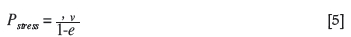
where: Oy is the vertical field stress and e is the extraction ratio
Pillar design procedure
After determining the pillar strength and pillar stress, the factor of safety (FoS) of the pillar can be calculated as follows:

For primary extraction, the minimum design FoS of pillars is 1.6. Due to the effect of the explosives used and poor ground conditions, the authors reviewed the current practices by measuring the actual pillar dimensions in a bid to calculate the actual factor of safety. Redesigning of pillars was considered where current pillar system is not adequate. The conclusion will be drawn after analysis of the results.
Explosive properties
Ammonium nitrate-fuel oil (ANFO) is a supreme explosive used in the mining industry. Its advantages include simple production, low cost, and lack of sensitivity to mechanical impact during mechanical loading into drill-holes (Mather, 1997). ANFO has also some disadvantages, which include lack of water resistance and low detonation parameters, which reduce its use to dry blast-holes in truncated compact rock masses (Maranda, 2011). Since the type of explosive used has an effect on support systems, the authors reviewed the literature on ANFO as well as the other bulk explosives, which include emulsion and watergel. The merits of bulk emulsion explosives over ANFO and packaged products include easy transportation and handling, increased safety, string charging, low gas emissions, water resistance, full coupling, increased velocity of detonation, detonator sensitivity, and improved work environment (Maranda, 2011). ANFO generates a lot of gases upon detonation, thereby widening pre-existing cracks. ANFO usage will therefore result in the formation of keyblocks, which will lead to an unstable hangingwall. In addition, the cut slice will increase due to overbreak and more poor hangings will be formed that require intense barring-down. Barring down becomes a risky operation due to frequent keyblocks and is also time-consuming, leading to failure to meet production targets.
Research approach
A comprehensive revision of the background literature was conducted as per the requirements of the project objectives. The background literature was then combined with contributions from the relevant experts in the field of study, such as rock mechanics engineers on a practical level. A field study of the areas of concern was supplemented by the contribution of experts in order to assemble a system of results that would be used for analysis.
Research criterion
The research started with the literature review on geological and geotechnical factors, underground support systems, mining methods, and types of explosive used. In order to obtain a clear understanding of the existing mining and support system, a study was carried out in all sections of the mine with poor ground conditions, which included Levels 14 to 24. Underground observations, recordings, and data collection were done in these sections. Observations and analysis were carried out on the geological structure of the orebody to identify the nature and magnitude of the jointing and faulting system. The effects of current mining practices and explosives used were assessed. Interviews were also conducted as part of the study approach. Observations were made in each level and the following parameters were measured and noted:
>Structural data - number of joints, separation of joints etc.
>Pillar dimensions
>Stope widths of each gully
>Time taken to support one gully
>Fallout heights
>Type of support used.
The results of these observations were analysed using rock engineering principles.
Geotechnical logging
This exercise comprised the methodical collection of all fracture statistics of the underground rock face. The data collected included joint roughness, joint sets, joint alteration, joint water, stress reduction factor, and ROD. These parameters were used in the calculation of the O rating of the pillars.
Rock mass classification
The determination of the rock mass state was critical to the investigation. Various techniques were applied to determine the ground classes in the research area. A comparative analysis of these techniques was then conducted to select the most effective method. Substantiated recommendations of the suitable support to be installed were based on the chosen method. The methods that were used include:
>The O system
>RMR
>MRMR.
Performance of installed support elements
Installed support elements used at the mine include rockbolts, shotcrete, and straps. These were analysed for their performance and effectiveness with regard to the fallout heights and the ground characteristics by means of log data and previous reports to ascertain whether failures could be attributed to the support, the conditions, or both. The analyses included examining situations of failure and of likely failure.
Investigation of the effectiveness of pillars
The pillar strength calculations were carried out through measurement of pillar heights and widths. The stress acting on a selected pillar was determined by calculation. Pillars are usually less than the designed size due to poor blasting and can undergo spalling attributed to poor ground. The frequency of such occurrences was investigated with the view to highlight the short-term and long-term problems associated with these practices.
Blast design and mining practices
The current blast design and explosives used were analysed to:
>Attain the planned face advance through efficient blasting
>Mitigate overbreak for grade control and mine design purposes
>Reduce damage to rock
>Identify the explosives suitable for use in poor ground conditions.
Project constraints
Constrains encountered during the research included the following:
>Measuring of pillars was rather dangerous as rockfalls are mostly from the shoulders of pillars
>Difficulties in logging of some ends due to waterlogging or delays in pumping out water.
Results
The results are based mainly on geotechnical data collected from the area of research. This includes results from rock mass classification methods, numerical modelling, reef-subparallel planes, FoS approach, stoping dimensions, and pillar strength. The current support system data was also included.
Evaluation of rock mass classification
The rock mass was classified according to each of the three systems, which are the RMR, MRMR, and the Q system. The three methods were compared to identify the most suitable method of ground classification.
Q system
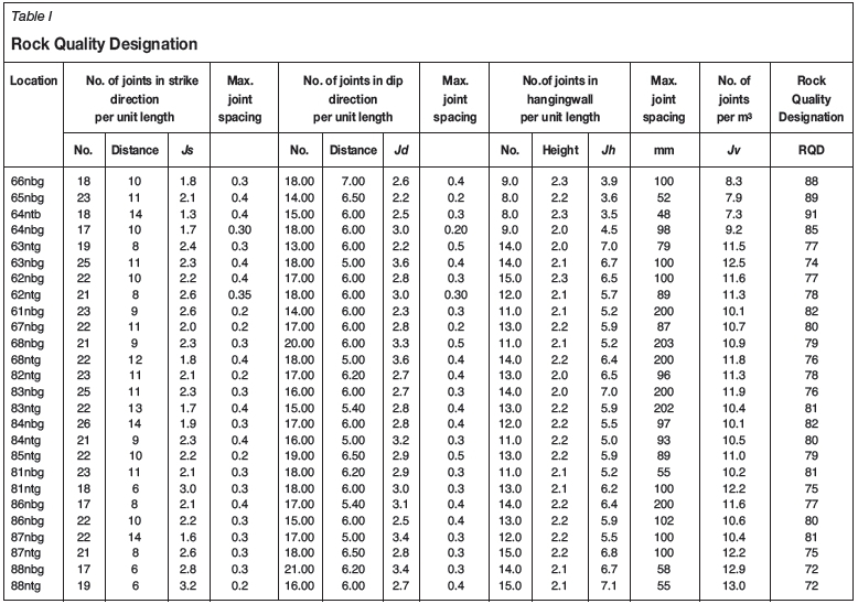
Table II shows the data used to calculate Q in each bord.

where Jx represents Js, Jd, and Jh.

Using Equation [2], RQD = 115-3.3Jv
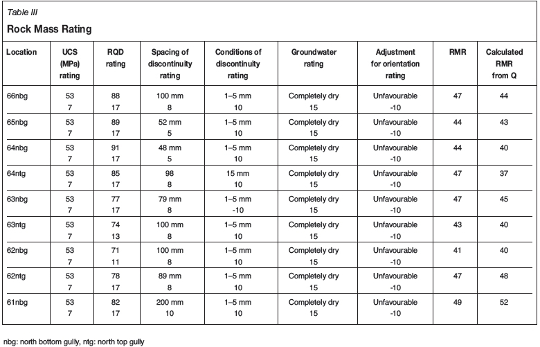
Rock Mass Rating
Table III shows the RMR calculated from Bieniawski's six parameters for each gully.
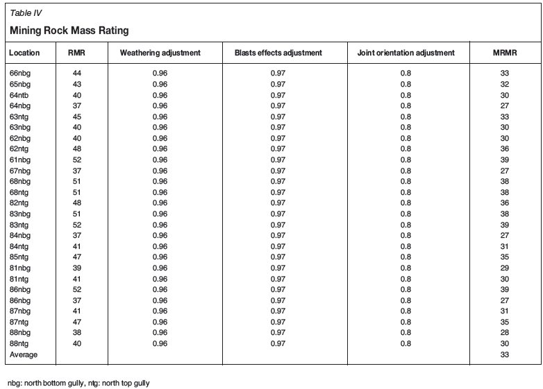
Mining Rock Mass Rating (MRMR)
The calculated RMR was adjusted to calculate the MRMR. A blasting effect adjustment of 97% was used, together with a weathering adjustment of 96%, and 80% for joint orientation. Table IV shows the adjusted RMR to give the MRMR.
RMR = 9lnQ + 44
The average RMR is below 50, which shows that the rock mass is poor. RMR values from Bieniawski are comparable with calculated values from Q ratings.
Rock-related risks due to the three joint sets are reduced by cutting larger pillars and through the use of cable bolts. In Ground Control District-D (GCD-D), the bord is reduced to 6 m and the in situ pillars are designed to be 3 χ 3 m for shallower areas (up to 160 m depth) and 3.5 χ 3.5 m for depths greater than 160 m. The main pillars measure 3 χ 10 m and 10 χ 3.5 m in most sections. The authors also measured the main pillar dimensions and calculated the infringements. The actual pillar dimensions of in situ pillars were measured and the FoS in the gullies calculated.
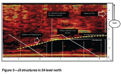
J3 structures are found in the hangingwall and ground penetrating radar (GPR) is used to identify these structures. The authors, with the assistance of geotechnicians, took GPR data and assessed the orientations and the average depth into the hangingwall. Analysis was conducted to ascertain whether the 1.8 m resin bolts and cable bolts currently used are sufficient. Figure 3 shows a typical slice obtained. A clino-rule was used to determine the dip of J1 and J2 structures. The authors deduced that J1 joint set is the dominant joint set, with an average strike direction of 088° and an average dip of 70°. The J2 joint set has an average strike of 005° and dips at an average of 65°. The J1, J2, and J3 joint set data from GPR was used in numerical modelling.
Analysis of results
Structural data analysis
The Q values obtained indicated that the rock is extremely weak. The values of the measured RMR were comparable with the calculated values from the Q values. From this, it can be deduced that the ground conditions in the area of research pose a risk due to high probability of potential unstable blocks. The authors recommend that the mine uses more systems for rock mass classification, since a single system cannot give a clear indication of the quality of the rock due to its inherent limitations. For GCD D, 1.8 m bolts are currently used and are spaced at 1 m by 1 m. Barton's Q chart was used to determine the appropriate support system for GCD D as shown in Figure 4.
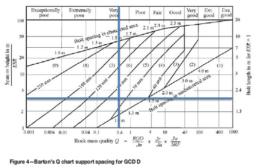
Based on this chart, the current support system used seems to be adequate, although other systems need to be considered also in the design of the required parameters. The fallout height was found to be 1.8 m in the research area. Roofbolts with a length of 1.8 m are therefore considered inadequate to clamp the overlying layers, since there will be no bond length. The use of shorter roofbolts has resulted in support failure, hence new systems of tendons need to be designed. The issue of reef-subparallel planes and numerical modelling will be discussed later in this paper.
All joints in the area of research are currently assumed to be dry; however, the authors recommend the use of hydrological surveys to obtain a clear picture of the groundwater. Groundwater reduces the stabilizing normal stress acting on discontinuity planes, hence weakening the rock. From the results of rock mass classification, it can be concluded that adequate support is required for safe mining practices. A new roofbolt system envisaged to improve safety and productivity is discussed later in this paper.
Ground penetrating radar (GPR) analysis
A slice showing reef-subparallel planes is shown in Figure 3. It can be noted that shallow-dipping planes occur at a depth greater than 1.8 m into the hangingwall. The current support system of 1.8 m length is not adequate to clamp these layers, hence a new system that uses longer roofbolts needs to be implemented to reduce the risk of support failure and possible injuries, fatalities, and equipment damage. All these factors lead to heavy cost to the mine, hence it is of paramount importance to improve safety and productivity through the implementation of the new support system. The authors therefore recommend the use of longer roofbolts in addition to the cable bolts used.
Numerical modelling analysis
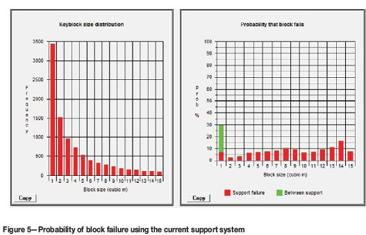
JBlock was used to deduce the probability of failure of keyblocks in the gully. The structural data for the three joint sets, together with tendon data, was used to simulate unstable keyblocks. The authors started by simulating unstable keyblocks using the current support system of 1.8 m roofbolts spaced at 1 m by 1 m. The area simulated is a 6 m gully in order to check the effectiveness of the current support.
Figure 5 shows the probability at which various blocks fail using the current support system consisting of grouted tendons 1.8 m in length spaced at 1 m by 1 m in poor ground conditions. From the histograms, it can be seen that the probability of block failure for 1 m3 blocks is 30% and the probability of maximum support failure is 16%. The probability of both block falls and support failure is thus too high. The current support system is inadequate. Integrating the results from all the techniques used, longer roofbolts are required to give improved safety.
The new support system designed and simulated by the authors consists of grouted tendons with a capacity of 160 kN, 2.1 m length, and spaced at 1.2 χ 1.2 m. The new system yields the results shown in Figure 6. The probability of block failure for 1 m3 blocks decreases to 11%, and the maximum support failure to 4%.
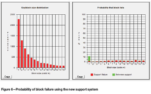
Taking into account a cost-benefit analysis, a comparison was made between the current support system and the new support system Although the 2.1 m tendons are more expensive than the current 1.8 m tendons, taking into consideration the cost-benefit analysis it can be concluded that the recommended system gives more benefits than the current support system. As well as improved safety, the new system leads to a decrease in support density since the tendons will be spaced at 1.2 χ 1.2 m as opposed to the current roofbolts spaced at 1 χ 1 m.
Evaluation of pillar design and cutting practices
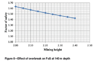
The authors evaluated the pillar design and cutting practices in poor ground conditions. Actual pillar dimensions in various bords were measured and the resulting factors of safety were calculated (Figure 7).

The results show that most teams have failed to maintain the required safety factor of 1.6 due to stoping overbreak. Figure 8 shows how overbreak reduces the FoS.
Stoping overbreak is caused by poor ground which unravels unpredictably, and also by ANFO explosive being used. It is thus critical to redesign pillars so that they are less influenced by a small change in overbreak. Pillar robbing also affects the FoS. Zvarivadza (2012) illustrated the relationship of probability of failure and FoS as shown in Figure 9.
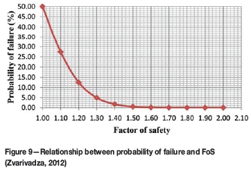
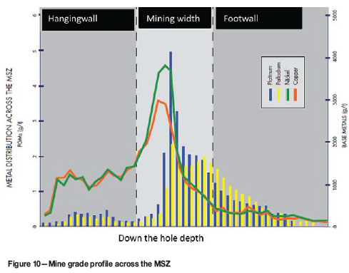
From Figure 9 it can be seen that for a FoS of 1.6, the probability of pillar failure is 0.5%, and at the lowest FoS of 1.33 obtained for Bord 66 (Figure 7), the probability of failure increases to 5%. A decrease in FoS therefore increases the probability of failure, hence it is critical to implement a pillar design that is less influenced by overbreak since the ground conditions are poor. Moreover, an alternative to ANFO needs to be considered to reduce stoping overbreak and unravelling of the rocks. Ore dilution occurs as a result of overbreak, as seen in Figure 10, since the grade of PGMs decreases above and below the required slice.
Conclusions
Safe mining practices and installation of adequate support lead to stable excavations. This review of the current support systems used in poor ground at a Zimbabwean platinum mine shows that the current support systems are not adequate in poor ground conditions. The presence of reef-subparallel planes at depths greater than 1.8 m into the hangingwall implies that the current tendons used will fail to support keyblocks. The current type of explosives used also results in stoping overbreak, which decreases the factor of safety and increases PGE dilution. The ground conditions thus require redesigning of the pillars and tendon system to improve productivity and safety. The current design assumes that all joints at the mine are dry, but the effect of groundwater weakens the cohesion of some joints, which increases the frequency of unstable keyblocks. Barring down using pinch bars is time-consuming and is regarded as a risky exercise, since the barring team is exposed to unstable blocks with a higher probability of failure. Because of frequent unstable blocks, barring down using pinch bars wastes more cycle time, which has led to most sections failing to meet their production targets since fewer faces are prepared.
Recommendations
> A study of the new support system designed by the authors is recommended. Longer roofbolts of 2.1 m length spaced at 1.2 χ 1.2 m are proposed, as opposed to the current bolts of 1.8 m length spaced at 1 χ 1 m. The 2.1 m roofbolts are more expensive than the current roofbolts; however, there is improved safety and less support density with the 2.1 m roofbolts. The extra cost of the roofbolts will be offset by the increased spacing, since fewer roofbolts will be used
>A study of alternative explosives is recommended to minimize rockfalls. ANFO explosives generate a lot of gases, which widen the joints. The authors recommend that the mine uses bulk emulsion, which is a low-energy explosive, in poor ground conditions
>Additional support is required where there is pillar robbing. The use of timbers and pillar bolting is recommended to improve strength
>The mine should use both empirical and numerical modelling to design the optimum support, since relying on one system has limitations
>The use of hydrological surveys is recommended to determine joint water. Hydrological surveys will give an indication of the exact groundwater conditions within joints, thereby increasing safety by designing for the actual groundwater conditions
>The use of mechanical scalers is recommended in poor ground conditions to improve both worker safety and productivity. Fewer faces being prepared result in failure to meet production targets, hence the use of mechanical scalers will improve productivity
>The authors recommend redesigning of pillars to improve safety and production
>Smoothwall blasting is recommended in poor ground conditions to minimize excavation damage
>Adequate training of workers and close monitoring is required when drilling.
References
Brown, E.T. and Hoek, E. 1980. Rock mass classification. Underground Excavations in Rock. Institution of Mining and Metallurgy, London. pp. 40-60. [ Links ]
Barton, N., Lien, R., and Lunde, J. 1974. Engineering classification of rock masses for the design of tunnel support. International Journal of Rock Mechanics, vol. 6, no. 4. pp. 190-235. [ Links ]
Bieniawski, Z.T. 1989. Engineering Rock Mass Classification. 1st edn. Wiley, New York. [ Links ]
Brady, B.H. 1985. Rock Mechanics for Underground Mining. 2nd edn. Allen and Unwin, London. [ Links ]
Maranda, A. 2011. ANFO detonation parameters. Central European Journal of Energetic Materials, vol 8, no. 4. pp. 280-291. [ Links ]
Mather, W. 1997. Bulk Explosives. https://miningandblasting.files.wordpress.com [Accessed 13 December 2014]. [ Links ]
Oberthür, T., Melcher, F., Buchholz, P., and Locmelis, M. 2012. The oxidized ores of the main sulphide zone, Great Dyke, Zimbabwe: turning resources into minable reserves - mineralogy is the key. Platinum 2012. Proceedings of the Fifth International Platinum Conference. Ά Catalystfor Change', Sun City, South Africa, 17-21 September 2012. Southern Afican institute of Mining and Metallurgy, Johannesburg. pp. 647-671. [ Links ]
Prendergast, M.D. 1989. The platinum deposits of the, Great Dyke, Zimbabwe. Magmatic Sulphides - The Zimbabwe Volume. Proceedings of the 5th Magmatic Sulphide Field Conference, 3-13 August 1987. Prendergast M.D. and Jones, M.J. (eds). 1st edn. Institution of Mining and Metallurgy, London. pp. 43-69. [ Links ]
Wilson, A.H. 1972. A hypothesis concerning pillar stability. The Mining Engineer, vol. 131, no. 1. pp. 409-417. [ Links ]
Wood, D. 1987. Support in underground hard rock mines. https://rocscience.com [Accessed 10 December 2014]. [ Links ]
Zvarivadza, T. 2012. Evaluation of pillar design systems for low reef platinum mining. MSc thesis, University of Witwatersrand, Johannesburg, South Africa. [ Links ]
Paper received Dec. 2015.
Paper written on project work carried out in partial fulfilment of BSc. (Mining Engineering)

