


Services on Demand
Article
 English (pdf)
 Article in xml format
 Article references
Indicators

Related links
-
 Cited by Google
 -
 Similars in Google
Share

 Permalink
Journal of the Southern African Institute of Mining and Metallurgy
On-line version ISSN 2411-9717
Print version ISSN 2225-6253
J. S. Afr. Inst. Min. Metall. vol.116 n.1 Johannesburg Jan. 2016
http://dx.doi.org/10.17159/2411-9717/2016/v116n1a10
PAPERS OF GENERAL INTEREST
New gas nitriding technique using the interior of the nitrided pressure vessel as the process chamber
R.W. NellI; M. KleingeldII; L. LiebenbergII
IWestinghouse Electric SA, Zwartkop, South Africa, Postgraduate candidate, North-West University
IICentre for Research and Continued Engineering Development, North-West University (Pretoria Campus), Lynnwood Ridge, South Africa, also Consultants to TEMM International (Pty) Ltd. and MCI (Pty) Ltd
SYNOPSIS
The need to nitride the interior of large machine housings, which are also pressure vessels, for use in a high-temperature gas reactor resulted in the development of a suitable new nitriding technique whereby the vessel interior is used as a process chamber while being heated in a conventional top-hat heat treatment furnace. However, this new concept introduced several mechanical design challenges, such as an extended-length fan shaft, a high-temperature bearing, and sealing flanges for operation under extremely high temperatures. A prototype nitriding plant was constructed and operated to verify the design. The different tunnels machined inside the forged vessel were nitrided evenly by measuring and balancing the gas flow through each tunnel. Test specimens placed at different positions in the housing were also nitrided during the process. The nitrided specimens were subjected to microhardness and layer thickness tests. Measured gas flow rates and other operational data confirmed the inverse proportionality between ammonia supply flow rate and measured crack ratio, as well as a crack ratio temperature dependence, typical of conventional gas nitriding processes. The design and operation of the nitriding plant were successful and a nitride layer thickness of 400 μηι and a hardness of approximately 1100 VHN were achieved. This proves that a large pressure vessel can be successfully nitrided using the vessel's interior as a process chamber.
Keywords: gas nitriding, pressure vessel, process chamber
Introduction
Nitriding of the inner surface of the housing of an experimental Pebble Bed Modular Reactor (PBMR1) core unloading device (CUD) was required. The CUD housing is a pressure vessel measuring 3 χ 2.2 χ 1.5 m and weighs 14 t. It forms the housing and structure for a large machine assembly with a number of moving metal parts and valves which make contact with the housing interior surface.
The most important reason for nitriding the CUD housing was to prevent cold welding between the moving metal parts and its lining surface, especially inside the PBMR helium gas pressure boundary. Friction in a helium environment causes cold welding between components made of similar steels, since there is no oxygen to replenish the oxide layer on the surface of the steel when wear takes place; a similar phenomenon is encountered in space and high-vacuum applications (Johnson and Keller, 1996; Moeller and Noland, 1968; Lúcia et al., 2006). A nitride layer also provides improved wear, corrosion, and fatigue resistance (Pye, 2003; Nisbett, 2005; Ashrafizadeh, 2003; Kenan, Mehmet, and Mehmet, 2000; Nathalie and Yves, 2006).
However, there are no nitriding facilities in South Africa that are able to nitride such a large pressure vessel. Furthermore, no records or evidence could be found that such a large workpiece had ever been nitrided before. Most commercial off-the-shelf nitriding systems ( e.g. Nitrex) cannot contain a component as large as the CUD housing. The cost of a custom-built commercial system was prohibitive, and therefore an alternative methodology had to be adopted. The objectives of this work were the purposeful design, building, commissioning, and qualification of a suitable nitriding plant to nitride the housing of the first PBMR CUD prototype.
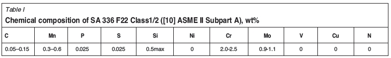
The CUD housing was designed as an ASME VIII (Division 1) pressure vessel (American Society of Mechanical Engineers, 2003a) and was constructed from ASME pressure vessel code steel. The CUD housing forging material is a Cr-Mo steel alloy that meets the ASME specification of SA 336 Grade F22, with chemical composition shown in Table I. The Cr and Mo contents are similar to those of the British Nitralloy steels (En 40 and En 41). No nickel is present because it is a nitriding inhibitor (Pye, 2003).
Gas nitriding
Nitriding was chosen above other surface treatment options as it is economical (Darbelly, 2006), requires no post-machining, and prevents cold welding during operation. Due to the fine tolerances of the CUD machined surfaces, nitriding is preferred as it can be performed after final machining. Also, when a steel surface is nitrided, it is chemically altered (nitrides), which inhibits the formation of an iron oxide layer.
Gas nitriding was found to be more suitable than plasma nitriding for this particular application, because a major disadvantage of plasma nitriding is the undesirable results obtained inside nitrided holes (Nisbett, 2005) due to hollow cathode/hole discharges. The CUD housing features many interconnected tunnels (holes) of varying diameter, thus rendering plasma nitriding unsuitable. Furthermore, modifying an existing plasma nitriding vacuum chamber to carry the weight of the CUD would be costly. Thus, gas nitriding was selected as the most suitable and economical process.
Development of a new nitriding plant
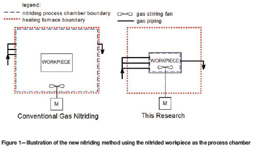
Since commercial off-the-shelf gas nitriding systems (e.g. Nitrex) cannot house a vessel as large as the CUD, a new method had to be developed. The new method proposed that the interior of the nitrided workpiece could be used as the process chamber, as this would be more economical and safer than building a large process chamber inside an existing furnace (cf. Figure 1). This method would also be appropriate, as only the interior of the workpiece needed to be nitrided.
However, before the full-scale plant was built, laboratory tests were performed in an electrical furnace on a small-scale vessel of the same material, in order to prove the concept's viability. The successful laboratory test resulted in the compilation of a set of operating instructions for the new nitriding process. These include the main nitriding parameters such as the process temperature, ammonia flow rate, and required process time. The two-stage Floe process (Floe, 1977) was also used to reduce the compound layer2, more often called the 'white' layer, thickness. Oxygen gas was used both as a catalyst and to prepare the surface for nitriding (Baranowska and Wysiecki, 2000).
From this experimental and literature data, the main nitriding parameters were thus determined to be:
> A process temperature of 555°C
> An ammonia flow rate of approximately 3000 l/h, as determined by the vessel's internal volume and required ammonia crack ratio
> A nitriding cycle duration of 48 hours.
The basic process requirements for the new nitriding process are similar to those of conventional gas nitriding (Pye, 2003; Nisbett, 2005).
> A process chamber is prepared inside the furnace. It contains the gases at a slight overpressure to prevent oxygen ingress. This overpressure can be provided by allowing gas to exit through water at a specific depth to provide back-pressure
> Nitrogen gas is used for purging before heating the vessel
> Oxygen can be used for surface preparation, i.e. to oxidize the surface, and as a catalyst. Other surface preparation techniques such as sputtering can also be used (Baranowska and Wysiecki, 2000; Baranowska, Szczecinkski, and Wysiecki, 2002)
> Gas nitriding is mostly performed by cracking anhydrous ammonia. This is because ammonia is metastable at the nitriding temperature and decomposes on contact with iron (Darbelly, 2006)
> A stirring fan is used to ensure even distribution of the process gas and heat (Matin, 1974)
> A gas analyser/Bunte burette is used to measure the ammonia dissociation rate.
The basic equipment requirements for a gas nitriding plant that uses the interior of a large workpiece as the process chamber are as follows.
> Heating furnace-An electrical or gas-fired furnace of a suitable size, capable of reaching 800°C, sustaining a heating rate of 50-100°C/h, and maintaining a temperature variance of ± 5°C is required
> Workpiece vessel preparation-Flanges for sealing all the ports on the vessel must be manufactured. Only 20-30 kPa overpressure will be required in the vessel to prevent air ingress. Flange seals must also be able to withstand a continuous operating temperature of 555°C
> Flange-rotating shaft penetration and fan. One sealing flange must be adapted to allow for a rotating shaft to penetrate. This shaft must penetrate deep into the vessel and allow the fitment of an impeller to the front end. For the CUD, this required the design of an extended shaft (2.5 m) for critical (whirling) speed and a high-temperature graphite bearing for operation inside the furnace at 600°C. The fan must further create sufficient turbulence in the NH3 gas to ensure adequate circulation
> Gas inlets-Sealing flanges should also be modified with three gas inlet pipe penetrations for N2, O2, and NH3. All inlet pipes should have flow control valves and flow meters. All piping, valves, and flow meters in direct contact with NH3 must be made of stainless steel and glass to avoid reaction between the NH3 and standard brass meters
> Gas outlet-A sealing flange should also be modified with an outlet pipe to allow gas to escape from the highest point in the vessel. The outlet gas includes H2, undissociated NH3, and N2. Therefore the gas should be bubbled through a water trap to dissolve the NH3, while the H2 should be flared off
> Temperature measwrement-High-temperature thermocouples are required both inside and outside the pressure vessel to maintain the correct process temperature. The CUD vessel's inner surface temperature is more important than the furnace temperature because of the large temperature gradient through the thick steel. Therefore, at least four thermocouples should be strategically positioned inside the vessel to record the temperature variation during operation. High-temperature thermocouple penetration fittings can be used to penetrate the sealing flanges for internal measurements. Depending on the size of the furnace, a sufficient number of thermocouples would also be required outside the vessel.
Figure 2(a) shows the constructed plant and CUD vessel process chamber, with the top-hat gas-fired furnace being placed over it. The orientation of the vessel inside the furnace is shown in Figure 2(b). The gas piping is buried underneath the sand of the top-hat furnace. Only the stirring fan shaft requires furnace wall penetration.
Operation of the new nitriding plant
The new nitriding procedure detailed above was tested in a large-scale implementation on the housing of the PBMR CUD prototype mentioned earlier. The process was controlled in such a manner as to fulfil the specific nitrided case requirements of a large depth and high hardness. Furthermore, to reduce the thickness of the white layer the double-stage gas nitriding cycle (Floe process) (Nisbett, 2005; Key to Metals, n.d.) was used.
The first cycle was planned as a normal nitriding cycle at 500°C and 15-30% ammonia dissociation. To achieve this dissociation rate at 500°C, a flow rate of four atmosphere changes per hour was required (Key to Metals, n.d.). This produced the nitrogen-rich compound layer at the surface. This cycle was maintained for 4-10 hours.
For the next cycle, the furnace was to be heated to 560°C and gas dissociation increased to between 75% and 85%. This two-stage process reduces the thickness of the white layer. The thin white layer that resulted (<0.025 mm) could be polished off after nitriding (Nisbett, 2005). According to Darbelly (2006) and Winter (2009), low KN set-points are required to achieve a zero-thickness compound layer (a low nitriding potential results in a low dissociation rate). The low dissociation rate during the first cycle of the Floe process therefore forms a thin-surface white layer. Further, during the high dissociation rate of the second stage, the deeper interior of the case was nitrided (Key to Metals, n.d.).
The parameters that were controlled for the desired nitrided case are:
> Increased furnace temperature, which resulted in increased case depth but reduced surface hardness (Pye, 2003). This also increased the dissociation rate (Darbelly, 2006; Winter, 2009)
> Increased process time, which resulted in increased case depth
> Increased gas supply rate, which reduced residence or incubation time, to retard nucleation (dissociation) for the formation of a compound white layer (Darbelly, 2006; Key to Metals, n.d.)
> Increased core material hardness and alloying element content, resulting in increased case hardness
> The correct surface pre-treatment (a high level of cleanliness and degreasing) and slight oxidation (which at temperature removes the last traces of organic residue and forms a very thin iron oxide catalyst layer for nitrogen infusion into the iron matrix) ensured a deeper case (Baranowska and Wysiecki, 2000).
Results
Plant operation observations
The plant was operated according to the procedure described in the previous section. Several significant observations were made.
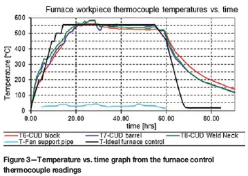
The first significant observation was a deviation from ideal behaviour concerning the actual heating rate that was recorded. To prevent excessive thermal distortion caused by an excessive temperature gradient in the metal workpiece, ASME VIII (American Society of Mechanical Engineers, 2003a) recommends a maximum heating rate of 56°C/h. Therefore, during operation, the burners were kept on hold.
This prevented the temperature from exceeding the prescribed limit within the thinner metal, with a lower thermal inertia. However, this led to a much lower heating rate of 20°C/h above 200°C being observed, as shown in Figure 3. The furnace workpiece thermocouples are used to measure the temperature of the thickest and thinnest metal sections, respectively. The temperature gradient limit was set to 20°C.
The second significant observation was that the ammonia dissociation rate is temperature-dependent. At a temperature of 500°C, during preparation for the nitriding cycle, dissociation rates of 45% were already measured. However, as the temperature was increased to 555°C at the same flow rate, the dissociation rate increased to more than 60%, which was too high.
A third significant observation was a problem encountered with the ammonia supply. The anhydrous ammonia cylinders froze in the cold winter morning conditions of the outdoor test site and could not provide the required continuous flow rate of 3000 l/h. It was therefore decided to reduce the furnace temperature to allow a lower ammonia flow rate to be supplied and to reduce the crack ratio and dissociation rate.
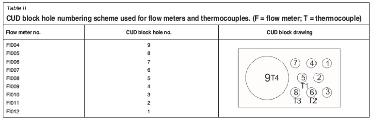
Finally, from the start of the nitriding process, it was noted that the flow rates of the nine gas exit flow meters were equal and did not require equalizing. Figure 4 shows that the exiting flow rate through each of the nine insert holes was equal to one-ninth the supply flow rate. However, an unexpected flow rate drop through the large hole (no. 9) of the CUD block (FI004, see Table II for numbering scheme) was recorded. This might have been due to nitriding fan turbulence.
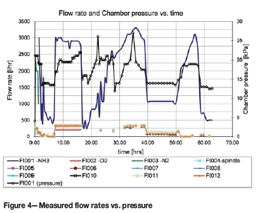
Between 8 and 15 hours, during the oxygen supply cycle, the exit gas flow through each of the nine insert holes was 350 l/h. After 34 hours into the nitriding cycle, a peak of 333 l/h was observed through each of the holes. At the reduced NH3 supply flow of 1050 l/h, the exit flow was 100 l/h from each hole.
Measured and predicted crack ratios
Generally, the double-stage nitriding process requires a low dissociation rate for the first 4-10 hours of the nitriding cycle (Key to Metals, n.d.). This produces a shallow white layer from which diffusion into the main case structure occurs. In the second stage, a higher dissociation rate of 75 to 85% is required (Key to Metals, n.d.).
To achieve the low initial dissociation rate of between 15% and 35% at 500°C, ammonia needs to be supplied at a sufficient flow rate so that four atmosphere changes per hour are maintained in the process chamber (Key to Metals, n.d.). According to calculations for the CUD, this equates to an ammonia supply flow rate of 3000 l/h at 550°C.
The CUD interior reached the required nitriding temperature after 23 hours. However, crack ratios of 64% were already measured after 18 hours. This occurred at 2 am and thus the available flow was low because the ammonia cylinders had already cooled considerably due to the high flow and low ambient temperature of 2°C. Unfortunately, due to the low ambient temperature the operators at the time could not adjust the flow rate upward and reduce the crack ratio. This would have resulted in the formation of a thicker white layer than planned. Due to the deviation in supplied flow, the two-stage Floe nitriding process was not followed correctly.
Figure 5 shows the crack ratio and flow rates as a function of time. It is apparent that the crack ratio and ammonia supply flow rates are inversely proportional to each other (Key to Metals, n.d.). The unexpected low measurements at about 20 hours might be due to human error in operating the Bunte burette. Figure 6 shows the overall trend of lower crack ratios obtained at lower surface temperatures.
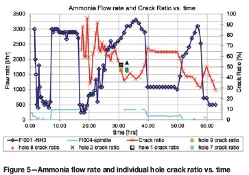
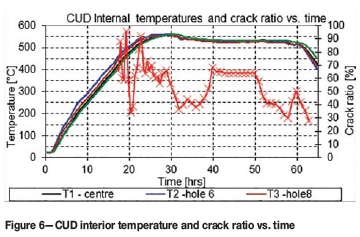
Figure 5 further shows that with a supply flow rate of 3000 l/h and stable temperature conditions after 31-37 hours, a desired crack ratio of 35% to 37% was measured. This confirms instructions from Nisbett (2005) and Key to Metals (n.d.). Later, between 40 and 50 hours when a supply rate of only 1000 l/h could be reached, a higher crack ratio of 65-70% was measured. An external ammonia dissociator was therefore not necessary.
Figure 5 also shows the crack ratios measured from the flow of the individual insert holes at 31-34 hours. These measurements correlate well with the measurement of all nine combined tube flows. The crack ratios of insert holes no. 3, 4, 5, and 7 were close to 48% at 33 hours, and those of insert holes no. 1, 2, 8, and 9 were close to the combined flow measurement of 47% at 31 hours. This proves that the mixing fan functioned effectively and that all nine insert holes of the CUD would be nitrided equally. The good correlation can also be attributed to the fact that all nine exit tubes were subjected to the same back-pressure.
Nitriding specimens
After the plant was decommissioned and the sealing flanges were removed, several nitriding specimens were collected from the insert holes. Specimens were marked according to the insert holes in which they were placed.
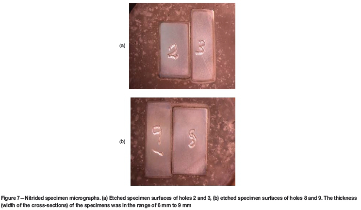
First, micrographs were taken of each prepared nitrided specimen's cross-section. The polished surface was etched with Nital specially prepared for the grade F22 steel. Some micrographs are shown in Figure 7, where the samples in the figure have a cross-section of approximately 10 χ 5 mm. A distinctly darker region (the nitrided layer) was seen on all nitrided specimens. It was deduced from the micrographs that all nine insert holes were nitrided to an equal depth.
A microhardness profile was then generated by making indentations with a 100 g Vickers indenter from the specimen surface, on the edge of the cross section, to beyond the nitrided ridge, as seen in Figure 7. This procedure was followed for three of the specimens (holes no. 2, 8, and 9), with the results shown in Figure 8. Since similar results were found for all three holes, it was deemed not necessary to obtain microhardness profiles for the rest of the holes. The samples tested from the three holes are representative of the different insert hole geometries, thus implying similar microhardness profiles for the other specimens.
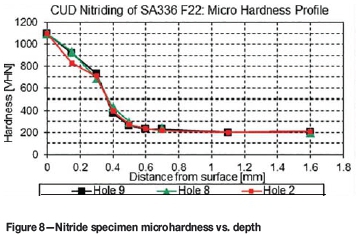
Figure 8 shows that that a surface hardness of 1100 HV was obtained on all three samples. The hardness then gradually decreased to 740 HV at a depth of 300 μm at a rate of 1.2 HV/μm. At a depth of 300 m the hardness underwent a sharper decrease to 376 HV at the end of the effective case depth of 400 μm. The hardness curve then decreased more gradually to a depth of 700 m. From 700 μm to 1 mm depth the hardness reduced at a very low rate to the material core hardness of 200 VHN.
The total nitride layer thickness can also be deduced from the microhardness profile. Ashrafizadeh (2003) defined the nitrided case depth as the depth where the hardness is 10% above the core hardness. From Figure 8 it can thus be deduced that the nitrided case depth is 500 μm.
In comparison to microhardness profiles recorded in other applications (Pye, 2003; Ashrafizadeh, 2003), the high surface hardness recorded here is maintained to a relatively deep depth. However, since the measurement resolution for this test was only every 150 μm, the existence of a constant hardness up to 150 μm could not be established. Comparison of the hardness profile in Figure 9 with those of other steels (Ashrafizadeh, 2003), however, reveals that it is rare to have both a surface hardness above 800 HV and a case depth more than 200 μm. For instance, plasma nitrided En 40B steel, nitridable steel, has a surface hardness of 900 HV and a case depth of only 220 μm (Ashrafizadeh, 2003).
It can thus be concluded that the CUD nitriding process was successful, since both a high hardness and a deep nitride case were achieved. This can be attributed to the high a nitridability of the SA 336 F22 CUD housing steel and the long duration of the nitriding cycle (48 hours).
Discussion
The following factors were found to influence the quality of the nitrided case.
> An increased furnace temperature resulted in an increased case depth. However, the high nitriding temperature of 555°C was maintained for only the first 10 of the 48 hours of the nitriding cycle, as shown in Figure 6. It is therefore uncertain whether furnace temperature could have contributed much to the 400 m effective case depth that was achieved
> The second important parameter is the process time. The long nitriding cycle time of 48 hours is the only parameter guaranteed to be responsible for the increased nitrided case depth
> Correct surface pre-treatment also resulted in increased case depth. Since the initial oxygen supply lasted seven hours, much longer than the intended two hours, this could have caused the high initial dissociation rate
> The low initial ammonia supply flow rate resulted in an increased crack ratio. The high initial crack ratio could have caused a compound, or 'white', layer (see footnote 2) and also the high surface hardness. If ammonia flow had been better controlled during the first four hours of the nitriding cycle, a shallower white layer of less than 25 m with the Floe process (Nisbett, 2005) should have been guaranteed. It is therefore possible that a hard, brittle, white layer had formed on the surface. Unfortunately this cannot be confirmed from a microhardness profile, since the actual hardness of the white layer could not be measured because it was too thin (Ashrafizadeh, 2003). The existence of this layer can be confirmed only by scanning electron microscopy (SEM) or X-ray diffraction, whereby a (ε+ γ) phase needs to be identified
> The nitriding tests on the specimens from all nine insert holes were similar. This can be attributed both to the equal flow rates and the equal crack ratios that were measured, as shown in Figure 7
> The maximum attainable hardness was effectively limited by the material composition. The SA 336 F22 material contains 2-2.5% chromium and 0.9-1.1% molybdenum (Table I). Owing to the high Cr concentration, CrN forms, which results in a hardness of more than 800 HV (Nisbett, 2005). The high surface hardness of 1100 HV is therefore attributed to the chromium content of the F22 material.
Conclusions
A new method of constructing a nitriding process chamber has been developed, using the large nitrided workpiece itself as the process chamber. This required the design of an extended-length, 2.5 m mixing fan shaft to penetrate a pressure boundary at a temperature of 600°C. A high-temperature gas sealing bearing was also developed, as well as various high-temperature gas-sealing penetrations. This new method also required the temporary modification of a conventional gas-fired heat treatment furnace for use as a gas nitriding heating facility.
This novel gas nitriding technique (Preisser and Seif, (1993) patented a dissimilar, but related technique) can be applied for nitriding the interior of engine blocks (Pinedo, 2003), large valves, or any enclosed vessel where the interior will be subjected to high friction, a moderately corrosive environment, or cold welding of internal components.
The successful operation of this new gas nitriding technique represents a first attempt at producing one of the largest single nitrided forgings to date. Micrographs and microhardness profiles confirmed a nitride layer thickness of 400 μm and a surface hardness of 1100 HV. These results meet and exceed the target values for the nitride layer.
The experimental investigation further confirms previous research showing the inverse proportionality between ammonia flow rate and dissociation as well as the dependence of crack ratio on temperature (Pye, 2003). The observed flow rate and crack ratio data validate the theory that ammonia should be supplied at four atmosphere changes per hour to ensure a crack ratio of 15-30% (Pye, 2003; American Society of Mechanical Engineers, 2003b). By monitoring the gas flow and crack ratio through each of the nine holes in the CUD housing, it was confirmed that equal flow rates and crack ratios resulted in equal nitrided case depths and hardness.
This work also shows the importance of maintaining low crack ratios during the first stages of the nitriding process. Adequate process control is, however, difficult due to the slow temperature transients involved with such a large workpiece. Although the process control was not ideal and various other experimental errors were made, the prototype nitriding plant nevertheless operated successfully. With improved process control and other minor adjustments, it would therefore be possible for this novel, semi-portable nitriding technique to compete with commercial gas nitriding furnaces at a fraction of the cost.
Acknowledgements
The authors would like to thank the following people for their contributions to the project:
Chris Koch (metallurgical engineer at SAMS (Pty) Ltd and contractor for Westinghouse Electric South Africa (Pty) Ltd performed laboratory testing and provided dissociation measurement tools.
Mike Nieuwoudt (CUD design engineer at Westinghouse Electric South Africa (Pty) Ltd) assisted with the design of the high-temperature equipment and defined the need for the project.
George Mathews and Doug Velleman proofread the manuscript and made valuable suggestions.
Professor Waldo Stumpf of the University of Pretoria's Department of Materials Science and Metallurgcal Engineering for advising that there is no need for further phase identification tests or SEM micrographs to prove the existence of the nitriding layer (even if a white layer could have formed).
References
American Society of Mechanical Engineers. 2003a. Boiler and Pressure Vessel Code (ASME), Section VIII Division 1, Edition 2001 with Addenda. [ Links ]
American Society of Mechanical Engineers. 2003b. Boiler and Pressure Vessel Code (ASME), Section II Materials Edition 2001 with Addenda. [ Links ]
Ashrafizadeh, F. 2003. Influence of plasma and gas nitriding on fatigue resistance of plain carbon (Ck45) steel. Surface and Coatings Technology, vol. 173/174. pp. 1196-1200. [ Links ]
Baranowska, J. and Wysiecki, M. 2000. Influence of surface pretreatment on case formation during gaseous nitriding. Surface and Coatings Technology, vol. 125. pp. 30-34. [ Links ]
Baranowska, J., Szczecinkski, K., and Wysiecki, M. 2002. Increasing of gas nitriding kinetics via surface pre-treatment. Surface and Coatings Technology, vol. 1151-1152. pp. 534-539. [ Links ]
Darbelly, J. 2006. Gas nitriding: an industrial perspective. Presentation, Department of Materials Science and Engineering, McMaster University. http://mse.mcmaster.ca/graduate/seminar/2005/ [Accessed 28 July 2009]. [ Links ]
Floe, C.F. 1977. A study of the nitriding process effect of ammonia dissociation on case depth and structure. Source Book on Nitriding. Unterweiser, M. and Gray, A.G. (eds.), American Society for Metals. pp. 144-171. [ Links ]
Johnson, K.I. and Keller, D.V. 1966. Adhesion between atomically pure metallic surfaces; Part IV- the effect of contamination on the adhesion of metallic couples in ultrahigh vacuum. NASA-CR-71147, Syracuse University, New York. [ Links ]
Kenan, G., Mehmet, D., and Mehmet, C. 2000. Effect of ion nitriding on fatigue behavior of AISI 4140 steel. Materials Science and Engineering A, vol. 279. pp. 207-216. [ Links ]
Key to Metals. Not dated. Cast steel: gas nitriding. www.steel.keytometals.com/Articles/Art132.htm [Accessed 28 July 2009]. [ Links ]
Lúcia, V., Santos, A.B., Vladimir, J., Trava-Airoldi, A., Evaldo, J., Corat, A., Nogueira, C., and Nélia, F.L. 2006. DLC cold welding prevention films on a Ti6Al4V alloy for space applications. Surface and Coatings Technology, vol. 200. pp. 2587-2593. [ Links ]
Matin, Y.I. 1974. Means of improving furnaces for gas nitriding, UDC (047): 621.785.532.662.5:621.783. Translated from Metallovedenie I Termicheskaya Obrabotka Metallov, vol. 3, pp. 42-46. Consultants Bureau (a division of Plenum Publishing), New York. [ Links ]
Moeller, C.E. and Noland, M.C. 1968. Cold welding tendencies and frictional studies of clean metals in ultra-high vacuum. Wear, vol. 11. p. 386. [ Links ]
Nathalie, L. and Yves, V. 2006. Fatigue strength improvement of a 4140 steel by gas nitriding: Influence of notch severity. Materials Science and Engineering A, vol. 435-436. pp. 460-467. [ Links ]
Nisbett, E.G. 2005. Steel forgings: design, production, selection, testing, and application. ASTM International, Materials Park, Ohio, USA. [ Links ]
Pinedo, C.E. 2003. The use of selective plasma nitriding on piston rings for performance improvement. Materials and Design, vol. 24. pp. 131-135. [ Links ]
Preisser, F. and Seif, R. 1993. Method of nitriding workpieces of steel under pressure. US patent 5211768. www.freepatentsonline.com/5211768.html [Accessed 28 July 2009]. [ Links ]
Pye, D. 2003. Practical Nitriding and Ferritic Nitrocarburizing. ASM International, Materials Park, Ohio, USA. [ Links ]
Winter, K.M. 2009. Gaseous nitriding: in theory and in real life. Technical Paper of United Process Controls, Process-Electronic GmbH, Heiningen, Germany. [ Links ]
Paper received Feb. 2013
Revised paper received Sep. 2015
© The Southern African Institute of Mining and Metallurgy, 2016. ISSN 2225-6253
1 South African engineering company PBMR (Pty) Ltddesigned the Pebble Bed Modular Reactor.
2 A dual-phase γ' (Fe4N) and ε (Fe3N) iron nitride ceramic layer that forms as an undesirable constituent in conventional single-stage nitriding. It is extremely hard and brittle, and can flake during operation if more than just 1 μm thick

