


Services on Demand
Article
 English (pdf)
 Article in xml format
 Article references
Indicators

Related links
-
 Cited by Google
 -
 Similars in Google
Share

 Permalink
Journal of the Southern African Institute of Mining and Metallurgy
On-line version ISSN 2411-9717
Print version ISSN 2225-6253
J. S. Afr. Inst. Min. Metall. vol.116 n.1 Johannesburg Jan. 2016
http://dx.doi.org/10.17159/2411-9717/2016/v116n1a5
PAPERS - FURNACE TAPPING CONFERENCE
An overview of the design, operation, and maintenance practices relating to tap-hole management on a PGM smelting furnace
B. van Beek; T.J. Goff; P.E. Nel; E. Rex
Lonmin, South Africa
SYNOPSIS
PGM smelting furnaces are known for operating at significant high superheats. Safe and efficient tapping of both the slag and matte phases can be achieved only through sound tap-hole management practices. This paper gives an overview of the tap-hole management approach followed at Lonmin's Western Platinum smelter. Five circular AC furnaces are operated, with each furnace comprising essentially a crucible and auxiliary equipment. Within the crucible, the slag and matte tap-holes are situated at different elevations. The slag phase is tapped at a higher elevation than the matte phase. At the three older furnaces, tapping is done by the conventional method of lancing open the tap-hole and closing it with a dolly. However, at the two newer furnaces, tap-holes are opened with the aid of a drill and closed with a mudgun. Tap-hole management can be divided in a number of aspects. In order to achieve a safe opening and closure every time, Lonmin distinguishes between three important aspects; namely, the design of the tap-hole system, the operating practices followed, and care and maintenance. The paper briefly explains the design of the tapping channel and cooling requirements in order to handle superheated matte, and the difference in design of the matte and slag tap-holes. Mention is also made of the importance of auxiliary equipment, which includes the launders, fume extraction, granulation water, and mudgun and drill units. Improvements made to the matte tap-block design are discussed. The monitoring, alarming, and safety systems related to matte and slag tapping are reviewed, and tap-hole life and different wear mechanisms are described. Tapping can be done in a safe manner only if the tap-holes and equipment are maintained properly. This topic includes tap-hole refractory repair practices, as well as improvements made in order to reduce repair time and to extend the time between deep repairs. The importance of the correct tap-hole clay selection in order to nurse the tapping channel after each tap is also discussed. Finally, the paper touches on some research and development work that was done in order to improve the monitoring of the condition of the tap-block by means of fibre optic temperature sensors.
Keywords: PGM smelting, tap-hole management, matte tapping, superheat
Introduction
Lonmin's Western Platinum smelter commenced operations in December 1971 with the commissioning of a 7.5 MVA six-in-line furnace smelting Merensky Reef concentrate. Since then a number of process changes and improvements have been made to the smelting complex. The latest addition was the 12 MVA furnace no. 2, commissioned in July 2012.
As can be seen from the smelter process flow sheet in Figure 1, concentrated slurry or filter cake produced from the concentrators is dispatched to the smelter complex. After offloading, the slurry is blended to a base metal range of 3.2-5.5%. Plate filters are used to dewater the slurry to produce a filter cake, which is then dried through a flash dryer with hot air and stored in silos before being fed to the furnaces.

The smelting furnaces make use of electrical energy to melt the dried concentrate. As the concentrate melts, two liquid phases form - a lighter magnesium-iron silicate-based slag, and a denser molten matte. The platinum group metals, together with the base metal sulphides, report to the furnace matte phase, which settles to the bottom of the furnace via gravity separation. The matte is tapped from the furnace at a temperature of 1400-1500°C. Five furnaces are used in different combinations to achieve the required production output. The focus of this paper will be on the tap-hole management on the 60 MVA furnace no. 1, which was commissioned in 2002.
The liquid furnace matte is poured into Peirce-Smith converters, where it is further processed to produce a converter matte that is transported to the base metal refinery.
The furnace matte and slag are tapped on a regular basis. Such tapping needs to be performed as safely and efficiently as possible. In order to achieve safe opening and closure every time, Lonmin smelting operations distinguish between three important aspects; namely the design of the tap-hole system, the operating practices followed, as well as care and maintenance.
Tap-hole system layout and design
Owing to the different physical properties of liquid matte and slag, the tap-hole layouts and designs for these two phases are completely different.
Slag tap-hole system layout and design
A total of three deep-cooled copper slag tap-blocks are installed at furnace no. 1 (Figure 2). The slag is in direct contact with the water-cooled copper and a freeze lining is formed between the liquid slag and copper during tapping. The centre of the slag tap-hole is situated 860 mm higher than the centre of the matte tap-hole.

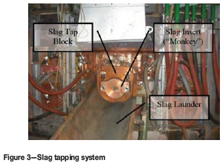
The slag tapping system (Figure 3) consists of a slag tap-block, slag insert (also known as a 'monkey'), and a slag launder. A total of six thermocouples are used to monitor the copper of the slag tap-block in order to detect any temperature excursions for alarming purposes. The slag insert tap-hole diameter is initially 65 mm and the tap-hole needs to be decommissioned when it is eroded to 80 mm. At an estimated slag thermal conductivity of 1.8 W/mK, the heat flux removal capacity is sufficient to maintain a slag freeze lining, but not to freeze matte. Thus it is important to maintain the matte and slag levels within the control limits.
A constant supply of cooling water at a velocity of 3 m/s is of utmost importance in order to ensure safe tapping of the slag. For this reason, apart from the normal cooling water supply pumps, an emergency header tank as well as a diesel-generated pump, is installed for emergency conditions.
The slag launder is constructed of steel and is also water-cooled. The impact area of the slag stream is protected sacrificial refractories installed in the first part of the launder. The slag that is being tapped from the furnace is granulated in a jet of water at flow rate of 800-900 m3/h, as can be seen in Figure 4. Tapping temperatures range from 1550-1650°C, depending on the feed composition.

A mudgun and drill were used for a brief period in 2004 on the slag side to assist with tap-hole opening and closing, but after an incident, the review recommended reversion to the conventional opening and closing of the slag tap-hole. A fume extraction hood is installed above each slag tap-hole to limit the tapping operators' exposure to fumes.
Matte tap-hole system layout and design
The matte tap-hole system comprises three deep-cooled matte tap-blocks. As a result of the high superheat (>600°C above liquidus) of the furnace matte, it is necessary to deep-cool the tapping channel in order to avoid frequent refractory repairs and consequent production delays. However, not only the tapping channel but also the area around the tapping channel needs to be cooled. Each matte tap-block is surrounded by flanker coolers on the sides as well as a lintel cooler above, as can be seen in Figure 5. A total of 24 thermocouples are used per tap block to monitor hot face copper temperatures.

Key learning outcomes from tapping incidents have led to several improvements being made to the tap-block design over the years. One of the first improvements, made in 2004, was the extension of the mag-chrome tapping channel length and the introduction of a larger tapping module called the 'Mickey block'. As can be seen from Figure 6, the original tapping channel was much shorter than the current design. It was difficult to do online tap-hole repairs on the short tapping channel design as the original design consisted of only four tapping modules.
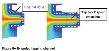
The Mickey block with its surrounding blocks was positioned deeper into the furnace in order to protect the copper-cooled area above the tap-hole. Currently, the tapping channel consists of five tapping modules plus the Mickey block. The longer tapping channel of just over 1 m assists in throttling the flow rate as well as enabling more intermediate online repairs to extend the life of the Mickey block.
Originally the furnace was commissioned with only two matte tap-blocks (Figure 7), but a third tap-block was added to the furnace in 2008 as a second improvement to the tap-hole system. The third tap-hole assisted in increasing the duration between deep tap-hole repairs. An additional benefit is that in the event that a problem is experienced with one of the tap-holes, production can still continue while preparation is made for a deep tap-hole repair.

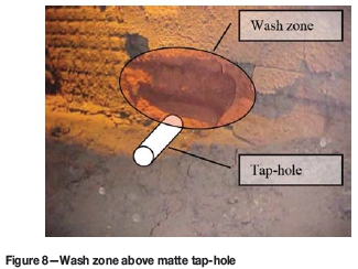
Experienced gained during repairs indicated that the area above the matte tap-hole experiences the highest heat flux during and after tapping. This results in a higher wear rate, thus the need for additional cooling and protection in this wash zone area. The risk to the wash zone, which can be seen in Figure 8, was that any high matte level excursion could result in copper damage as heat fluxes up to 130 kW/m2 were measured. This initiated the third improvement, which focused on reinforcing the area above the matte tap-hole.
A number of design changes were made in this regard. The first was the introduction of a copper-cooled lip in order to cool the refractories above the tapping channel. This worked well, but wear was still experienced on the copper-cooled lip, due to both corrosion and erosion. As a result of the success of the graphite cooler design in the slag zone it was decided to protect the copper above the tap-hole with graphite as well. The alternative design was implemented in 2010 with the introduction of a graphite-protected copper lintel cooler situated in the wash zone above the matte tap-hole. Results from the furnace rebuild in 2013 indicated that the graphite design lintel cooler performed well. Copper corrosion in the area above the tap-hole still occurred, but to a lesser extent. The corrosion was as a result of the loss of graphite contact in some of the areas.
During the 2013 rebuilt a different design of graphite lintel cooler was installed. The graphite is now slotted in horizontally and it is foreseen that the graphite will maintain in contact with the copper for longer during the next campaign.
Auxiliary equipment
Apart from all the changes mentioned above on the matte tap-holes, tapping matte from furnaces also requires some auxiliary equipment. At furnace no.1, two mudgun and drill units are used to assist in the opening and closing of the matte tap-holes. The design of these units allows for manual as well as semi-automatic operation. In semi-automatic, the mudgun moves and stops at the selected tap-hole to be drilled or plugged. The lowering, drilling, and plugging action is still left to the tapping operator.
A number of improvements have been made to the mudgun and drill units over the years. These include modifications to the positioning limits, moving the clay loading panel further away from the clay loading chamber, introducing a castle key system during clay loading, as well as controlling the units from a dedicated PLC with its own UPS systems.
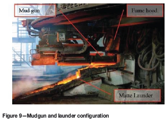
The alumina-chrome refractory-cast matte launder, mudgun unit, and fume extraction hood can be seen in Figure 9. The matte launder consists of two pieces, the spout and the launder itself from where matte is transferred to a 12 t refractory-lined ladle.
Tap-hole monitoring and alarming
As mention above, the hot face copper temperatures of both the matte and slag tap-blocks are monitored. Based on results of finite element analysis a high and high-high alarm have been set for each copper temperature. The philosophy followed is that a high temperature alarm will send an action alarm to the SCADA operator and a high-high alarm will trip the furnace power. Similarly, the differences between the inlet and outlet water temperature are also monitored. Alarms are raised on these water temperature differences based on predefined alarm limits.
It is also important to detect any water leaks on the cooling circuits. For this reason the outlet flow rates of each water-cooled circuit are monitored. The low flow alarms are used to alarm and trip the furnace. The water temperatures and flow rates are used to calculate a heat flux for that specific area in the furnace. Alarming is also done based on the specific heat flux in that area. An online pressure testing system is also used on a daily basis to test the pressure drop over each cooling circuit while no tapping is taking place.
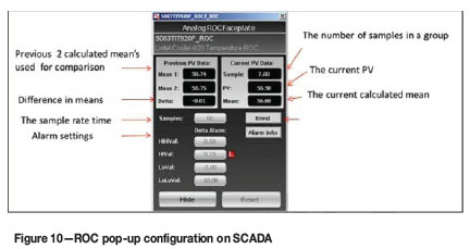
From the analysis of previous tapping incidents the high-high alarm limit is sometimes not sufficient to warn the tapping floor personnel to evacuate the area. The time from the start of the rise in temperature until the actual incident was in some cases between 1 to 2 minutes. For this reason a rate of change (ROC) alarm was introduced, which measures the rise rate of both the water and copper temperatures. The ROC alarms are based on the difference between two sample means. Figure 10 shows the SCADA pop-up of the lintel cooler on furnace no. 1.
These initiatives to improve the tap-hole design and monitoring are, however, only one aspect of tap-hole management. The physical tapping operation, as well as the maintenance and repair of the tap-holes, are equally important.
Matte and slag tapping operations
Matte tapping is carried out to control the desired matte level in the furnace. The matte is tapped four to five times per shift, depending on the percentage matte fall. The tapping operation consists of drilling, lancing, tapping, and plugging steps as discussed below.
Drilling with mud-gun and drill
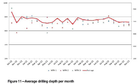
When opening a matte tap-hole during normal operations, a hydraulic mudgun and drill is used to partially drill open the clay-filled tap-hole until the solidified matte layer is reached. The average drilling depth to achieve this is normally between 700 and 900 mm. Before commencing with lancing, an operator measures the depth drilled and reports the measurement to the control room. In general, good drilling depths were achieved from 2011 to 2013, as indicated in Figure 11. An alignment check on the drilled hole is also done with a T-bar to prevent the operator from lancing skew in the event that the drill was misaligned.
After the measurement has been done, the mud-gun and drill unit is moved to the park position before lancing commences.
Oxygen lancing of matte tap-hole
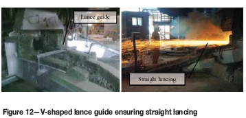
Oxygen lancing is performed by two operators to penetrate into the solidified matte. One operator is responsible for regulating oxygen flow through the lance pipe, while the second operator burns through the tap-hole with a 3 m long lance pipe until the liquid matte starts to flow. A V-shaped lance guide used by the operator (Figure 12) ensures straight lancing. The experience of the furnace tappers is of utmost importance to ensure prolonged tap-hole life. Every effort is made to limit the use of oxygen and the number of lance pipes used per tap is recorded for this purpose.
Matte tapping
The furnace matte is tapped into a 12 t refractory-lined ladle which is then transported to the converter by an overhead crane. The matte tapping temperature is measured using an optical pyrometer and must not exceed 1570°C. A furnace matte temperature exceeding 1570°C will cause the furnace to automatically power down. The tapping duration is monitored in order to determine the wear on the tap-hole refractories. Matte spoon samples are taken from the tapping stream and the analyses are used for metallurgical accounting and process control purposes.
Particular care is also taken to ensure that all three matte tap-holes are used evenly and that one tap-hole is not used more than the others. All tapping data from tapping events is manually recorded into the SCADA and stored on the INSQL server. This data is monitored on a weekly and monthly basis as matte tap-hole usage forms part of the furnace key performance indicators (KPIs).
Another important aspect during matte tapping is to ensure that limited amounts of slag are tapped through the matte tap-hole (slagging). The slag is chemically much more aggressive towards the refractory. Consequently, it is a practice to slag the matte tap-holes on a weekly basos to ensure that all matte and chromite layers are tapped out of the furnace.
Plugging of the matte tap-hole
When the matte ladle is almost full or when a mixture of matte and slag is detected, the mudgun and drill unit is brought from the parked position into the plugging position in semi-automatic mode. This operation is conducted from a refractory-protected mudgun cabin. The operator then lowers the mudgun and rams the clay into the tap-hole. In the event of a mudgun failure, manual clay stoppers are used to close the tap-hole.
Clay consumption is measured after every matte tap. On average 4 litres of clay per tap is used, and any anomalies are reported so that the counter can be fixed by the instrumentation department. Any excess clay can cause more gas to being released from the clay, which could damage the copper above the tap-hole. Less than 4 litres of clay could result in the tapping channel containing matte rather than being full of clay. Consequently, the next tap will take considerably longer and could result in damage to the tap-block due to excessive lancing. The clay consumption forms part of the weekly and monthly KPIs.
Slag tapping operation
Slag tapping is semi-continuous with a slag tap-hole open approximately 15-18 hours per day. The higher elevation of the slag tap-hole ensures that no matte is pulled into the slag stream when tapping. This is especially important when granulating slag with water as the presence of matte in the slag can lead to violent explosions.
The slag tap-holes are opened manually by oxygen lancing. No mudgun and drill unit is used. The liquid slag is granulated and the granulation water enters the slag pond with the granulated slag. The slag is scooped out of the pond using an automated grab crane and transported for further processing. The three slag tap-holes are used sequentially to ensure an even load on the wall and prevent cold spots developing, which will require vigorous lancing and will damage the tap block.
When the slag tap-hole must be closed, a manual clay stopper ('dolly') is used. This device is simply a cone-shaped clay plug on the end of a long steel bar. Using the bar, an operator inserts the clay plug into the running slag stream. When the plug is in position, a second operator taps the end of the steel bar with a hammer, driving the plug deeper into the slag tap-hole and stopping the flow of slag. A 10 mm steel bar is then hammered through the clay stopper to act as a 'leader bar' when opening the tap-hole the next time.
The slag temperature is measured during tapping and recorded similar to the matte temperatures. The slag temperature is normally between 1550 and 1650°C and slag viscosity is not a problem at these temperatures. As mentioned previously, the slag insert can wear back to a maximum of 80 mm before requiring replacement. Generally, damage to the water-cooled 'monkey' occurs during lancing operations. By following proper lancing procedures, the working life of the insert can be extended. The current life of a 'monkey' insert is approximately two years.
Spoon samples of the molten slag stream are taken and the analysis is used to calculate the PGM recovery.
Matte tap-hole repair and maintenance
The tap-hole refractories are deep-cooled with copper cooling elements. There are three copper cooling elements cooling the matte tapping channel - the deep matte waffle cooler, matte tapping spout, and the faceplate. All of these copper components rely upon the protection given by the tapping channel refractory bricks, and the refractory bricks are reliant on the cooling received from the copper components. It is imperative that these refractories are maintained on a regular basis.
Tapping channel refractory configuration
As indicated in Figure 7, the tapping channel consists of five tapping modules and one larger tapping module (the Mickey block). These tapping modules are surrounded by so-called 'doghouse refractories'.
The copper faceplate is also fitted with a refractory insert. The design allows for proper contact between the refractory insert and the first tapping module in order to prevent any matte leaking through between the copper-cooled faceplate and the first tapping module. The initial tap-hole diameter is 38 mm.
A summary of refractory modules with dimensions is given in Table I.

The tapping channel will wear over time and require periodic maintenance. Therefore, at furnace no.1 the matte tapping channel repair is split into two stages:
> One-to-five block repair (tapping modules)
> Deep matte tap-block repair (Mickey repair).
Each repair is discussed in more detail below.
One-to- five block repair philosophy
The decision to conduct a tapping module repair is based on the time it takes to fill a 12 t refractory-lined ladle. From operational experience, a tapping time of less than 11 minutes indicates possible wear of the tap-hole and requires a tap-block repair. The tapping modules on every tap-hole are replaced on a bi-weekly basis. From one to five tapping modules can be replaced, depending on the physical condition of the tapping modules during the repair. During this intermediate repair no doghouse refractories are replaced. The condition of the Mickey block is also monitored during these repairs.
Deep matte tap-block repair philosophy
A deep matte tap-block hot repair is done every 3 to 4 months, depending on the condition of the Mickey block. As mentioned above, the cold face measurements of the Mickey block will indicate when to plan for a deep block repair. From historical data and operational experience, a deep repair is planned when matte penetration into the Mickey block is so severe that only 20-30 mm of refractory brick remains. From a safety perspective, 20-30 mm brick is very close to the doghouse refractories and could lead to premature failure of the copper cooled block. The possibility also exists that the operators could lance skew, damaging the copper and cause a major breakdown.
Procedures for five and deep matte tap-block repair
The five and Mickey block repairs follow similar procedures. The only difference is the duration of the repair and the extent to which preparations must be made. For a one-to-five block repair, the tap-block is decommissioned at least eight hours before the repair and only the faceplate and tapping modules are removed during the repair.
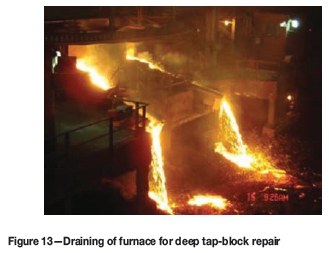
For a Mickey block, however, the entire furnace is drained (Figure 13) and all the matte launders and spout have to be removed. Two schools of thought exist around whether to drain the furnace or to conduct the deep tap-block repair with a full liquid charge. It is Lonmin's opinion that the risk of doing a deep repair without draining the furnace is too high, and that the additional throughput achieved with this practice is not worth pursuing.
A five-block repair can take two to four hours to complete. Power is reduced to between 2-3 MW only when the fifth block is reached. Power is increased again after the fourth block is replaced. Mickey block repair time ranges between eight to twelve and hours, excluding the draining and heat-up period. During this repair, contact is maintained on two phases to keep the bath liquid.
For additional precautionary measures during a five-block repair, a hole is drilled deeper than the fifth module with the mudgun. The surface temperature at the end of the drilled-in hole is measured before the repair. A surface temperature in excess of 300°C or rise rate of 1°C/min indicates that additional cooling is needed before the repair can be done. Forced cooling by means of fans and air blowing through a hose is used to cool the matte tap-holes.
The surface temperature is monitored continuously throughout the repair by a hand-held pyrometer, with each tapping module's surface temperature being recorded. Photographs and dimensions are taken of the tapping modules as they are removed for quality control purposes. Any signs of cracking of the modules or surrounding refractories are highlighted to management and the relevant action is taken.
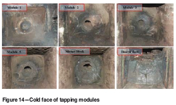
During a deep tap-block repair, the surface temperature is also monitored. Extra care is taken in order to ensure that no liquid matte runout occurs while breaking out the Mickey block. A typical repair and wear pattern of the tapping modules and Mickey block can be seen in Figure 14. As can be seen, the tap-hole diameter and penetration increases the deeper one breaks into the tapping channel.
After all the refractory has been replaced, the copper faceplate is reinstalled. Finally, a small fire is made in front of the tap-block to cure the castable refractories between the faceplates and launder.
Improvements made during deep tap-block repairs
Over the last six years, efforts were made to reduce the time taken to conduct a Mickey block repair. The aim was to prevent the hearth refractories from cooling rapidly, which can lead to gap formation. This could pose a major problem during the initial heating-up phase, as the bricks might not be completely sealed and matte penetration could occur, causing ratcheting of the hearth.
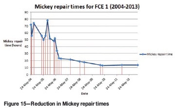
Since the re-commissioning of furnace no.1 in 2004, the average power-off time for a Mickey block repair has decreased from 60 hours to 12 hours in 2013. This power-off time excludes the draining and bath-building stages of the repair. Currently, the matte tap-to-tap duration is 3.5 days for a deep repair.
Figure 15 indicates how Mickey repair times have been reduced. It can be seen that the frequency of Mickey repairs has been reduced between 2004 and 2008. The Mickey repairs between 2010 and 2013 during annual shutdowns or after furnace incidents are considered as special causes and could not be documented and compared with the rest of the data, as the Mickey repair time could not be distinguished from other activities during these events.
The main contributors to the improvement were:
> Improved draining of the furnace to ensure a safe matte level
> Change in cooling method from liquid nitrogen to air
> Improvement in refractory preparation for faster Mickey block installation
> Repairs conducted at low power, typically between 1-2 MW (on/off) instead of switching off power to the furnace completely.
Apart from the reduction in repair time, a number of other improvements were made, as discussed below.
Improvements in matte tapping safety
As with any high-temperature operation, the risks of injury to tapping personnel are high. However, with the support of the dedicated tapping personnel, several changes were made to increase the safety of personnel and equipment.
Length of the tapping lance
The length of the oxygen lances was changed from 6 m to 3 m. This reduced the risk of skew lancing due to the flexibility of the lance, and also increased ease of operation.
Oxygen hose design
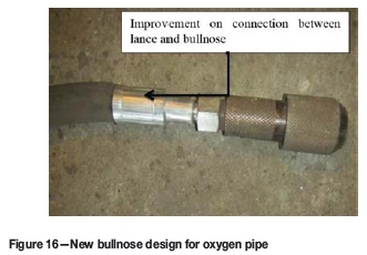
In the past, frequent incidents occurred where operators burnt their hands while lancing due to oxygen leaks. These leaks occurred between the connection of the bullnose and the flexible hose. The bullnose was subsequently re-designed to make the connection to the flexible hose more robust and less prone to leaks. Figure 16 indicates the new design.
Installation of a mild steel sacrificial plate
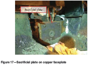
A sacrificial plate of mild steel is placed in front of the matte faceplate to protect the copper against hot matte splashes during the tapping process. The sacrificial plate is used as a consumable and is changed during every tap-block repair or when the plate is damaged during the tapping process. Figure 17 shows how the sacrificial plate is installed onto the copper faceplate.
Tap-hole clay
Tap-hole clay is used during the operation of the mudgun. Operating the mudgun during tap-hole closures is safer for tappers than conventional manual plugging of the tap-hole. The tap-hole clay also assists with repairing the tap-hole as the clay penetrates deep into the tapping channel, forming a protective layer during the next tap. The original clay used for plugging of tap-holes had a high volatile content (LOI of 8%), which meant that a lot of boiling occurred inside the furnace after tap-hole closures. This led to an increase in the wear rate in the wash zone. Since 2011, an alternative tap-hole clay with lower volatiles (less than 3%) and a higher alumina content (75%) has been used. Less boiling is observed, and protective layer is visible in the tapping channel during repairs.
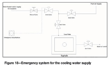
Installation of emergency push-buttons for faceplate
In the event that the copper face plate comes in contact with matte during the tapping process, water could leak from the faceplate into the liquid matte stream and cause violent explosions. In order to mitigate this risk, three emergency push-buttons were installed in each mudgun station for each matte tap-hole. When a leak at one of the tap-holes is detected, the emergency push-button is activated, closing the supply line valve of the cooling water to that circuit. The air supply valve automatically opens to flush the system, making it safe for the operators. The supply valve can also be closed from the SCADA or from a manual isolation valve in the tapping cabin. Figure 18 is a schematic diagram of the emergency system currently installed at furnace no. 1.
Fibre optic temperature measurement system
As part of continuous improvement on the condition monitoring of the tap-blocks, a fibre optic temperature measurement system was installed and tested on the matte tap-blocks. These fibre optic sensors provided temperatures at the surface of the copper. The sensor cables were installed in a grooved channel on the hot face of the matte tap-blocks. A protective tube was mounted on the copper blocks to accommodate the fibre-optic sensor. During the initial work, the following problems were experienced:
a. Gases from the process corroding the tube and damaging the sensors
b. Cable connections to the junction box burning off during tapping
c. Damage to the cable connections during tap-block repairs.
The latter two points were addressed, but to date corrosion is still is a problem.
Useful data was obtained from the sensors and could have been correlated with process conditions. Currently, ways to embed the fibre optic tube below the copper cooler surface need to be developed.
Conclusion
The Lonmin smelter team has come a long way in ensuring that tapping is conducted as safely as possible every time. As this paper has shown, the design, operation, as well as the maintenance of the tap-holes is crucial for successful operation of a furnace when tapping superheated matte.
Acknowledgements
The authors would like to acknowledge the operational staff at furnace no. 1 for their contribution in assisting with inputs and ideas during the design and operational changes. The contributions of the furnace designers at Hatch are also acknowledged with thanks.
©The Southern African Institute of Mining and Metallurgy, 2016. ISSN2225-6253. This paper was first presented at the, Furnace Tapping Conference 2014, 27-28 May 2014, Misty Hills Country Hotel, Muldersdrift, South Africa.

