


Services on Demand
Article
 English (pdf)
 Article in xml format
 Article references
Indicators

Related links
-
 Cited by Google
 -
 Similars in Google
Share

 Permalink
Journal of the Southern African Institute of Mining and Metallurgy
On-line version ISSN 2411-9717
Print version ISSN 2225-6253
J. S. Afr. Inst. Min. Metall. vol.116 n.1 Johannesburg Jan. 2016
http://dx.doi.org/10.17159/2411-9717/2016/v116n1a4
PAPERS - FURNACE TAPPING CONFERENCE
SlagFloTM: Modulating the flow in the tap-hole
S. Essack
Tenova Mining and Minerals (Pty) Ltd
SYNOPSIS
Tenova Pyromet's SlagFloTM control valve is designed to throttle the flow of molten slag in order to control the tapping rate. In addition, the SlagFloTM valve has proved to be a reliable tool for remotely closing the slag tap-hole during normal operation, as well as emergency conditions. This piece of equipment makes use of a water-cooled copper element that is hydraulically operated and attached directly to the slag tap-hole. The equipment is compact, simple to maintain, and cost-effective to purchase and install. It can be retrofitted to most existing slag tap-holes with minimal modifications. During the development phase, finite element method (FEM) and computational fluid dynamics (CFD) software was extensively used to model predicted operating conditions and to optimize the design. By using CFD, it was possible to understand the flow patterns inside the copper element and to optimize these to improve overall performance. The SlagFloTM valve was installed and commissioned in 2011/2012 on a 12 MW furnace as part of a new mineral wool plant built in the USA. It has performed well since its installation, despite operating under conditions in excess of the original design criteria. During the first 6 months of operation it quickly became the preferred method of closing the furnace, although the design intent was for occasional use during emergency shut down conditions only. Since replacing the mudgun as the main method of closing the tap-hole, a few minor changes were made to the installation in order to cope with the increased heat load and much higher frequency of use. The SlagFloTM valve has also been installed in South Korea, on two mineral wool furnaces designed and supplied by Tenova Pyromet in 2015. Both furnaces are scheduled to be in full production by the second quarter of 2016. Tenova Pyromet is investigating modifications needed to suit other commodity furnaces with more aggressive slag chemistries.
Keywords: slag valve, flow control, mineral wool, water-cooled copper, slag tapping
Introduction
During 2010, Tenova was awarded the contract to design and supply a 12 MW mineral wool furnace in the USA. This furnace required a slag flow control device for each of the two tap-holes. This provided the opportunity to develop a slag flow control valve based on previous experience. A robust design was required, as this is a continuous tapping process and the demands placed on the equipment are extreme. In addition, space constraints in the tap-hole area of a relatively small furnace meant a compact design that is easy to maintain was a requirement upfront.
Mineral wool manufacture
Mineral wool is manufactured by spinning molten aluminosilica slag into fibres. Fibres can be manufactured by blowing or spinning. Fibre lines can be fed by coke-fired cupola or by electric arc furnace. The mineral wool fibres are deposited in layers and may be combined with a resin binder, pressed, and baked depending on the final product. The mineral wool product has very good thermal and sound insulation properties.
Mineral wool is also referred to as slag wool or stone wool, depending on the raw material that is used. Slag wool is made from blast furnace slag, which is a by-product of steel production, while stone wool is made using aluminosilicate (basalt) rock as the raw material. (Crane and Mclaren, 2008).
Depending on the raw material used and the final processing, a wide variety of products can be made servicing the following roles (Saint-Gobain ISOVER, 2008; Eurima, 2011):
> Fire protection
> Ceiling boards/dry walling
> Filtering and gasket elements
> Growth medium for hydroponics
> Fibre addition to reinforce various plastics, friction materials, and coatings.
The typical slag composition and operating temperature range of a so-called 'stone wool' is shown in Table I.
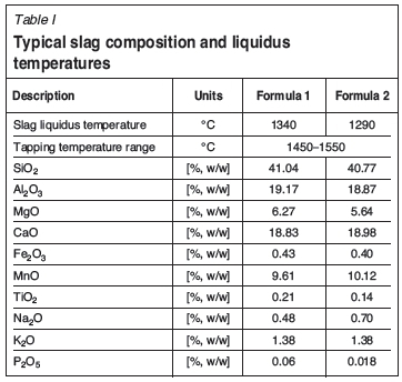
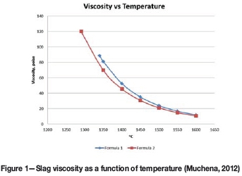
The slag viscosity is plotted as a function of temperature for these two slag compositions in Figure 1.
The challenge
Functional requirements
The slag valves are designed to modulate the flow of slag. This is a requirement imposed by the downstream spinning equipment. In order to maintain consistent fibre quality, the slag stream must be consistent and controlled.
The client specified that the slag valve should also be able to shut the slag tap-holes under emergency conditions, freezing slag inside the tap-hole and closing the furnace.
The mineral wool furnace is tapped on a continuous basis, with a scheduled stop approximately twice a month during which maintenance can be performed on downstream equipment. Before the stop in the production line, the slag tap-hole is closed and the furnace power reduced to idle the furnace. This quasi-continuous operation subjects all equipment in the tap-hole area, including the slag valve, to very high heat loads and does not allow for frequent maintenance.
As with many furnaces, space is at a premium in the tap-hole area. Since this is a relatively small furnace with two closely spaced tap-holes, the problem of space was compounded.
Figure 2 shows the slag tap-hole equipment, which comprises the following items:
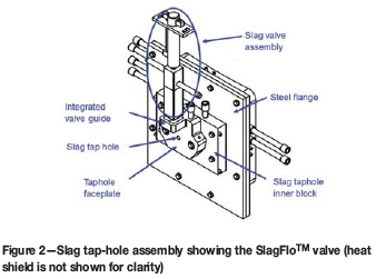
> Slag tap-hole inner block
> SlagFloTM valve assembly
> Tap-hole faceplate
> Integrated valve guide
> Steel flange.
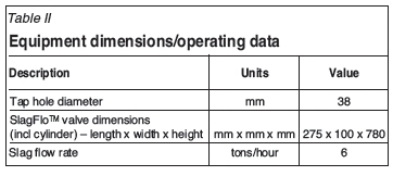
Equipment dimensions and operating data are shown in Table II.
The slag tap-hole inner block and tap-hole faceplates are both water-cooled copper elements. These pieces of equipment use a freeze lining design to protect the tap-hole equipment. The water cooling channels are designed to minimize the risk of explosion in the unlikely event of a burn-through of the tap-hole cooling elements. The water cooling circuits have fixed piping sections extending outward from the copper equipment. This is done in order to move the flexible hoses away from the high radiation and potential slag splash zone. The flexible pipes, which are less temperature-resistant than the fixed piping, are thus protected from the very high heat loads, extending their life.
The guide for the valve is integrated into the faceplate design. This guide acts as a mechanical limit to excessive horizontal movement of the slag valve.
Consistent flow of slag to the spinners is paramount, so position changes to the copper piston are made incrementally. The SlagFloTM valve is actuated remotely by a set of pushbutton controls or remotely from the SCADA. The control of the valve is a simple operator-controlled task. A combination of visual feedback of the slag stream and feedback from the spinner is used by the furnace operators to decide on what changes must be made to the position of the valve. If an emergency shut is required, the furnace operator lowers the SlagFloTM valve completely. This action slows the flow of slag, and the water-cooled elements freeze the slag inside the tap-hole, effectively closing the furnace. The SlagFloTM valve can be set up to close automatically under certain circumstance, like a furnace trip or loss of water, should the specific operation warrant this action. Using feedback from the spinning equipment to introduce an element of automation would be an area for future work.
The steel flange shown in Figure 2 is installed in order to facilitate tap-hole repair and replacement from the outside of the furnace. This flange is designed to act as a lifting support frame when the inner block is removed for maintenance or replacement and during first installation.
Modelling the design
A model of the SlagFlo™ valve was created using ANSYS software. A combination of FEA and CFD modelling was used to predict the equipment temperatures. This paper includes only the results of the CFD modelling. The boundary conditions for the CFD analysis are presented in Table III.
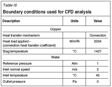
The heat transfer in the SlagFloTM copper piston is largely due to two mechanisms; (1) slag in contact with the copper and (2) cooling water on the copper. The heat transfer from the slag was represented by a convection heat transfer coefficient, on two faces of the copper. The heat transfer between the copper and the water, on the internal water passages, was modelled using the 'conservative interface flux' condition in ANSYS. The heat transfer on the remaining external faces of the copper is negligible compared with the other heat loads. No freeze lining was modelled on the copper. This represents the moment that the molten slag comes into first contact with the new copper valve.
A thin freeze lining in the region of 2 mm has been reported to form almost instantly (Nourse, 2014) but the purpose of the model was to confirm that the SlagFloTM valve would withstand the highest heat load incidents.
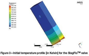
As shown in Figure 3, the initial simulations predicted temperatures in excess of 627°C (900K). As copper begins to lose its mechanical strength at approximately 360°C (Matweb, 1999), this temperature profile is unacceptable.
By optimizing the design of the flow channels inside the SlagFloTM valve, the simulated temperatures were brought down to within the acceptable range. Figure 4 shows that there are small areas, closest to the contact area with the slag, where the expected copper temperatures are at the limit of the acceptable range.
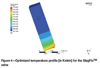
The SlagFlo™ valve is subjected to the force of the slag flow and the force of closing the copper piston against frozen slag build-up that may occur during the tapping cycle. Since these forces are relatively low, the acceptable design temperature for this specific case is higher than for other copper equipment typically specified by TENOVA.
The SlagFloTM copper piston is a consumable item and is expected to be replaced periodically as it wears. The wear pattern on the copper piston is expected to be asymmetrical, with the hot face side of the valve wearing faster than the cold face. The slag valve has been designed with enough material between the water channel and the slag to allow for approximately 30 mm of wear on the slag valve. Once the valve has worn back by 30 mm it must be replaced. If it is replaced at this stage, there will still be a safe amount of copper between the water and the slag.
Installation and operation
The equipment was installed at a plant in the USA at the end of 2011, and the furnace was switched-in during the first quarter of 2012. Reports of initial operation were positive and in line with client expectations. The SlagFloTM device operates consistently with the tap-hole partially closed. With the taphole 30-40% closed, production is consistent and stable at the required tapping rate of approximately 6 t/h. Once the tap-hole approaches 60% closed, the slag flow becomes inconsistent due to freezing in the tap-hole (Mogotlhong, 2015).
Shortly after switch-in, the SlagFloTM valve became the preferred method of closing the furnace, rather than the clay gun. The tap-hole is reopened directly by drilling, with lancing often not required at all. The SlagFloTM valve in the USA has been used to close the tap-hole at least 50 times between switch-in and the middle of 2015, excluding unplanned and emergency shuts (Mervos, 2015).
In Figure 5 the slag valve can be seen in operation. Note the uniform slag stream with the SlagFloTM valve partially closed. Figure 5 also shows how the flexible piping is largely shielded by surrounding equipment, which reduces the heat load (most of the flexible piping is not visible in this photograph).
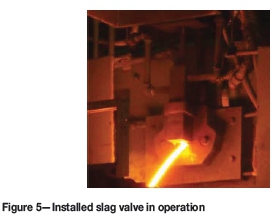
Figure 6 is a photograph taken of the SlagFloTM copper piston to show the wear pattern that was seen after some months in operation. The lower edge of the valve shows signs of erosion where the slag stream impinges on the valve. This occurs when heat flux in the area is high, before the slag has frozen against the valve. The horizontal striations are a result of the furnace operator removing the frozen slag from the copper piston. Overall, the wear on the slag valve is minimal, which supports the view taken on the acceptable temperature limits when modelling this piece of equipment.
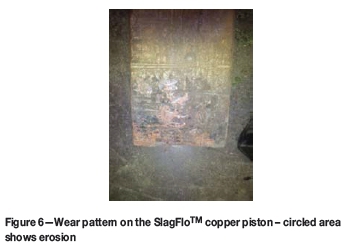
There are no significant signs of chemical attack, which is as expected for the mineral wool slags. Modifications are being investigated for processes where chemical attack would present a significant source of wear.
It has not been possible to collect data on the temperature profile inside the copper piston to date. However, the measured slag temperatures reported from the plant (Mitchell, 2014) have, on average, been 137°C higher than the maximum temperature expected and used in the modelling. These higher operating temperatures have not materially affected the life of the copper piston. The consumable portion is being replaced at 12-week intervals, which is consistent with initial expectations.
Modifications made after installation
Approximately 6 months after switch-in, the performance of the SlagFloTM valves was reviewed. Minor deformation had occurred in the support structure of the valve assemblies. This increased the clearance between the tap-hole faceplate and the slag valve and increased the time required to close the slag tap-holes. These support structures were replaced with an alternative design, and no further problems have been reported.
In addition, the client was experiencing accelerated wear on the seals of the hydraulic cylinder on one of the tap-holes. The cause was traced to localized degradation of the hydraulic fluid (water glycol) since the hydraulic supply pipes are routed past tap-hole one to reach tap-hole two (Mitchell, 2014). Additional modelling was done taking into account the higher temperatures recorded during operation. Based on the modelling work, a much longer water-cooled shield was designed to protect the SlagFloTM cylinder. Shielding was also added to protect the hydraulic fluid supply piping.
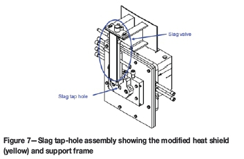
Figure 7 shows the slag tap-hole assembly with the longer water-cooled shield, which is approximately twice the length of the previous heat shield. Note how the shield extends to the top of the SlagFloTM valve guide on the tap-hole faceplate. This extended shield protects the hydraulic cylinder rod and seals from the high radiant heat loads.
What value does the SlagFlo™ valve add?
As a means of closing a slag tap-hole, the SlagFloTM valve offers a substantial saving in terms of equipment costs. The typically cost of the assembly is around 15% that of a mudgun machine. In addition to the cost saving, the space required for a SlagFloTM valve is substantially less than for a mudgun. The equipment does not require operating space since it is permanently attached to the shell.
For a very low capital investment, the SlagFloTM valve allows the furnace to be remotely closed under normal conditions and emergency conditions.
Conclusion
The use of computational modelling allowed for a relatively simple design optimization process and resulted in a design that performed well on the first installation. This design is well suited to slag tapping operations where there is a need to modulate slag flow, and has proved to be a reliable and robust method of shutting the slag tap-hole. The SlagFloTM valve can easily be installed as an emergency back-up to most slag tap-holes. It can also be installed in order to add a level of control upstream of slag granulation processes and improve their consistency and safety.
Tenova Pyromet is interested in further developing the SlagFloTM valve to accommodate more aggressive slags and incorporate a level of automated feedback.
References
Crane, A.E and McLaren, L 2008. Insulation materials: Rock and slag wool insulation: A sustainable choice. Insulation Outlook, July 2008. http://www.insulation.org/articles/article.cfm?id=IO080707 [Accessed 22 January 2014]. [ Links ]
European Insulation Manufacturers Association (EURIMA). 2011. Mineral wool applications. http://www.eurima.org/about-mineral-wool/mineral-wool-applications [Accessed 13 January 2014]. [ Links ]
Matweb. Material Property Data. 1999 Electrolytic tough pitch Copper, UNS c11000. http://www.matweb.com/search/datasheet.aspx?matguid=3c78d450e90f48c48d68e2d17a8e51f7 [Accessed 13 January 2014]. [ Links ]
Mervos, B. 2015. Armstrong World Industries Inc. Personal communication. [ Links ]
Mitchell, D. 2014. Armstrong World Industries Inc. Personal communication. [ Links ]
Mogotlhong, L. 2015. Tenova Minerals (Pty) Ltd, Personal communication. [ Links ]
Muchena, D. 2012. Tenova Minerals (Pty) Ltd. Personal communication. [ Links ]
Nourse, R.B.N. 2014. Tenova Minerals (Pty) Ltd. Personal communication. [ Links ]
Saint-Gobain ISOVER. 2008. Insulation materials, mineral wool. http://www.isover.com/our-solutions/Insulation-materials/Mineral-wool/Glass-or-stone [Accessed 13 January 2014]. [ Links ]
© The Southern African Institute of Mining and Metallurgy, 2016. ISSN2225-6253. This paper was first presented at the, Furnace Tapping Conference 2014, 27-28 May 2014, Misty Hills Country Hotel, Muldersdrift, South Africa.

