


Services on Demand
Article
 English (pdf)
 Article in xml format
 Article references
Indicators

Related links
-
 Cited by Google
 -
 Similars in Google
Share

 Permalink
Journal of the Southern African Institute of Mining and Metallurgy
On-line version ISSN 2411-9717
Print version ISSN 2225-6253
J. S. Afr. Inst. Min. Metall. vol.115 n.11 Johannesburg Nov. 2015
http://dx.doi.org/10.17159/2411-9717/2015/v115n11a16
PAPERS OF GENERAL INTEREST
1D numerical simulation of velocity amplification of P-waves travelling through fractured rock near a free surface
P. ZhangI; G. SwanII; E. NordlundI
ILuleå University of Technology, Sweden
II†Rock Mechanics & Mine Design, Canada
SYNOPSIS
The most widely used support design damage criterion for rockburst-prone mines is based upon kinetic energy, which is proportional to the square of the ejection velocity and is commonly expressed in terms of peak particle velocity (PPV). Field monitoring and back-analyses have shown that ejection velocities of the order of 10 m/s and higher can result from seismic events of moderate magnitude. Such velocities are much higher than those predicted using PPV obtained from scaling laws. It has also been found that the peak ground motion (i.e. PPV) on the surface of an excavation is preferentially amplified (by four- to tenfold) compared to the motion in solid rock at a similar distance from the source. However, the wave propagation and interaction processes involved within the fractured rock in generating high ground motion are very complex and are not well understood at this time.
In this paper, velocity amplification was investigated by modelling the dynamic interaction between fractured rock and a free surface using a 2D discontinuum-based numerical program, UDEC (Universal Distinct Element Code). A 1D model with a fractured zone was used to represent the fractured rock. Velocity amplification, quantified by PPV, predicted at the free end of the model was 2.0-3.6 times higher than the input velocity. It was found that the wave frequency, fracture stiffness, fracture spacing, and thickness of fractured zone are the main factors that affect the velocity amplification. The results have proved that the interaction of the seismic wave and multiple fractures near the free surface strongly influences the ground motion.
Keywords: rockburst, velocity amplification, fractured rock, free surface, numerical analysis
Introduction
Since mining-induced seismicity is almost inevitable in deep mines, ground support is generally employed to mitigate the risk of seismically-induced damage. The most widely used support design criterion for seismically-prone mines is one that seeks to maximize the absorption of the kinetic energy (plus potential energy if a gravity component is considered) of key rock blocks. Based on this criterion, design methods for rock support were first proposed by Wagner (1984) in South Africa and later improved, among others, by Roberts and Brummer (1988) and Kaiser et al. (1996).
The kinetic energy is a function of the mass in motion and the velocity at which the mass is moving, which is normally called ejection velocity. The general assumption is that the ejection velocity is related to the peak particle velocity (PPV). A common assumption is that the rock ejection velocity is equal to the PPV (Roberts and Brummer, 1988; Wagner 1984). This assumption is based on the observation that the dominant wavelengths from remote seismic events are typically much longer than the tunnel or drift dimensions and that wave reflections are ignored. Yi and Kaiser (1993) confirmed these assumptions with a theoretical evaluation of rock ejection from passing seismic waves and showed that ejection velocities under typical mining and seismicity conditions (dominant frequencies less than about 100 Hz) were less than, but close to, the PPV. However, in their analyses the rock mass was simplified as an elastic continuous medium, which is not true since the rock near the excavation surface in a deep mine is typically highly fractured due to high initial stress, excavation (blasting), mining-induced stress disturbance, etc.
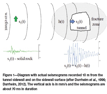
The amplification of wave motion in the walls of excavations in the deep hard-rock gold mines of South Africa has been observed and reported: peak velocity and acceleration parameters at the surface of an excavation indicate a four- to tenfold increase when compared to measurements within the solid rock (Durrheim et al., 1996). A diagram with actual seismograms recorded 10 m from the tunnel sidewall and on the sidewall surface measured by Durrheim et al. (1996) is presented in Figure 1. The observed amplification is considerably greater than the twofold amplification expected when a normally incident P- or S-wave reflects at a free surface. The effect is, additionally, although indirectly, confirmed by observations of wall-rock velocities which sometimes are of an order of 10 m/s and greater (Ortlepp, 1993; Stacey and Rojas, 2013). In practice, a site effect factor (i.e. velocity amplification factor) is sometimes applied as a multiplier to the incoming PPV to try to approximate the ejection velocity. Kaiser et al. (1996) are of the opinion that ejection velocities greater than the PPV are possible only if the ejected blocks are very small. However, they also concede that the ejection velocity could be higher due to stored strain energy around the opening also being transferred to the ejected rock and suggest an amplification factor of between 1 and 4 for conditions with energy transfer. A quantitative value for the site effect in Western Australian hard-rock mines has been quoted as about 2 or less as the fracture zone is more likely to be less than a metre and rarely more than two metres (Potvin et al., 2010). Mikula (2012) suggests that an average site effect factor of 3 may be typical at LongVictor Mine according to his experience. This effect is poorly understood, but amplification of the ground motion by a factor of up to 10 times is considered possible (Milev and Spottiswood, 2005).
Different mechanisms have been suggested to explain the source for this phenomenon: (i) resonance, which is discussed, with reservations by Durrheim et al. (1996); (ii) trapping of energy within a channel; (iii) energy release due to slab buckling (McGarr, 1997); and (iv) energy release due to softening (Linkov et al., 1998). In fact, none of these theoretical analyses can provide a satisfactory explanation for this complex phenomenon due to the many assumptions used. By explicitly coupling the fractures into the model, Hildyard (2007) studied wave interaction with underground openings in fractured rock and applied it to the rockburst problem in deep-level mining. He concluded that 'The damage potential from an event near an excavation cannot be simply inferred from aspects such as moment, magnitude and the proximity to the source centre, as this ignores the effect of the excavation and fracturing, i.e. simulations will be required for meaningful estimates of damage potential.
A literature review of this subject revealed that the degree of velocity amplification appears to be dependent on the frequency of the incident seismic wave, the fracture spacing, the fracture stiffness, and the thickness of the fractured zone around the excavation, together with the reflection of the wave from the excavation surface (e.g. Hildyard, 2007; Kaiser et al., 1996; Milev and Spottiswood, 2005; Zhao et al., 2008). In order to investigate velocity amplification and find the relationship between the velocity amplification factor and its influential factors, it was decided to conduct numerical analyses by explicitly considering the fractures in a model using discrete element modelling (UDEC). A 1D model with a fractured zone was used in this study and different fractured states of rock near the free surface and different loading frequencies were also considered in the analysis.
1D numerical modeling
Model description
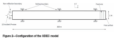
The general configuration of the UDEC model is shown in Figure 2. The one-dimensional elastic rock bar has a length of 300 m and a width of 1 m. The incident P-wave generated by applying a dynamic load normally on the left surface of the bar propagates through the model in a horizontal (x) direction. Parallel fractures with regular spacing are located near the right boundary and normal to the incident wave. A non-reflecting boundary is placed at the left boundary to avoid wave reflections from the artificial boundary. The right boundary is free of restraint to simulate the real free surface. Because it is a P-wave incidence, displacements only in the y-direction of the upper and lower boundaries are restricted.
Parameters of rock material and fractures
The properties of rock material adopted in the UDEC model were from LKAB's Kiirunavaara underground mine (Malmgren and Nordlund, 2008) and are listed in Table I. The P-wave velocity of the rock material is 5589 m/s.
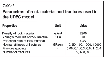
To theoretically or numerically model the effect of fractures on the propagation of plane seismic waves, the fracture is represented as a displacement discontinuity at the boundary between two elastic bodies (Pyrak-Nolte et al., 1990; zhao et al., 2008). It is assumed that the stress across the displacement discontinuity is continuous but the displacement is not. The ratio of the stress to displacement is called the specific stiffness of the fracture (interface) and characterizes the elastic properties of a fracture. In order to focus on how the elastic property of fractures affect the wave propagation, all fractures were 'glued' in this simulation, which means that infinite tensile strength and cohesion were assigned for all fractures. The normal fracture stiffness varied from 5 to 10000 GPa/m. The effect of the number of fractures and the fracture spacing was also studied and the parameters are listed in Table I.
Dynamic modelling considerations
It is commonly recognized that the mesh size in a numerical model significantly influences the accuracy of the results for wave propagation problems, whether the model is based on a continuum or discontinuum approach. Based on a study of the mesh size limitation in the finite element and discrete element method (Gu and Zhao, 2009; Kuhlemeyer and Lysmer, 1973) it was concluded that the mesh ratio (a ratio of the maximum element length to the smallest wave length in an elastic material) should be smaller than 1/8-1/12 to ensure numerical accuracy of wave propagation problems. To achieve a balance between computation efficiency and accuracy, the largest mesh ratio is set to be 1/28 for the following UDEC modelling.
Since the focus of this work was to study how a seismic wave interacts with fractures and a free surface, the material damping was ignored and the damping ratio in the UDEC model was set to zero in all analyses. In this case, the wave attenuation or amplification was caused only by the fractures and the free surface.
A half cycle sinusoidal P-wave pulse with the amplitude 0.1 m/s was applied normally at the left boundary. It propagated through the model in the horizontal (x) direction (see Figure 2). Different loading frequencies were used in the analysis, and they varied from 10 Hz to 800 Hz in order to cover the range reported for damaging seismic events.
Numerical results
The damage criteria of a rock mass under dynamic loads are generally governed by the threshold values of wave amplitude, such as the peak acceleration, the peak velocity, and the peak displacement; most often the peak velocity is used for seismic damage assessment. Therefore, only the peak particle velocity (PPV) was analysed in this paper. The magnitude of the velocity amplification factor, defined as the ratio of wave amplitude at the free end of the 1D model to the incident wave amplitude, was investigated. In order to analyse the effect of fracture spacing compared to wavelength, a non-dimensional fracture spacing (the ratio of fracture spacing to incident wavelength) was adopted in this paper.
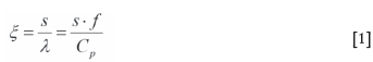
where
s = fracture spacing (m)
λ = incident wavelength (m)
f = wave frequency (Hz)
Cp= P-wave velocity (m/s).
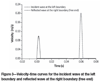
Wave reflection at a free end
When an incident compressive stress wave with a half cycle sinusoidal form reaches a free end in the rock bar, the wave is reflected as a tensile wave at the free end. The reflected wave and the tail of the incident wave are then superimposed. The PPV at the free end hence is doubled, as can be seen in Figure 3. This example is free of fractures; the material is homogeneous, isotropic, and linear elastic, and hence the velocity amplification factor at the free end is 2 and is normally independent of wave frequency.
Effects of multiple parallel fractures near free end
However, it has been reported that the wave transmission and reflection coefficients are functions of the fractured state of the rock (characterized by fracture spacing and fracture stiffness) and the wave frequency (e.g. Pyrak-Nolte et al., 1990). These effects have been explicitly studied using a 1D model with a fractured zone in the following sections.
Fracture spacing
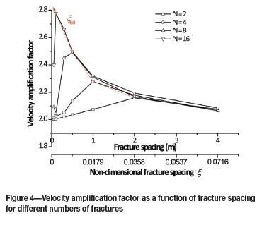
Figure 4 shows the velocity amplification factor as a function of fracture spacing (or non-dimensional fracture spacing) for different number of fractures. The fracture stiffness was 100 GPa/m and the frequency of the incident wave was set as 100 Hz. As the wave frequency was fixed, the non-dimensional fracture spacing is proportional to the fracture spacing. As can be seen from Figure 4, the velocity amplification factors vary with the fracture spacing and are larger than 2 within the investigated parameter range. With the increase of fracture spacing, the velocity amplification factor first increases until it reaches a peak and then starts to drop slowly. There is only one exception in the investigated fracture spacing range - when the fracture number is 8. In this case, the velocity amplification factor first drops slightly from a fracture spacing 0.05 m to 0.1 m. A critical value (ξcri) is defined in this paper at which the peak velocity amplification factor occurs.
Number of fractures (thickness of fractured zone)
Since the fractures were located near the free end at regular spacing, the thickness of the fractured zone is proportional to the number of fractures when fracture spacing is kept constant. Therefore, the effect of the thickness of the fractured zone can also be studied by investigating the effect of the number of fractures.
The velocity amplification factor as a function of fracture spacing for different numbers of fractures is shown in Figure 4. The change of the number of fractures does not change the trend of velocity amplification factor as a function of fracture spacing. For each curve, the velocity amplification factor first increases and then decreases with the increase of fracture spacing. When fracture spacing is fixed, the velocity amplification factor increases with the increase of number of fractures. With the increase of the number of fractures, the shape of the curves changes gradually. When the number of fractures is small, the curve is flat; but when the number of fractures is large, the curve shows more variation, i.e., a rapid increase with increasing fracture spacing followed by a more pronounced peak and then a rapid drop. This indicates that the velocity amplification factor is sensitive to the fracture spacing when the number of fractures is large. Also, the critical value of the non-dimensional fracture spacing (ξcri) for each curve decreases with increasing of number of fractures. When the fracture spacing is larger than 2 m (or the non-dimensional fracture spacing is larger than 0.036), the effect of the number of fractures (from 2 to 16) can be ignored within the investigated parameter range as all curves follow the exact same contours of each curve.
Wave frequency
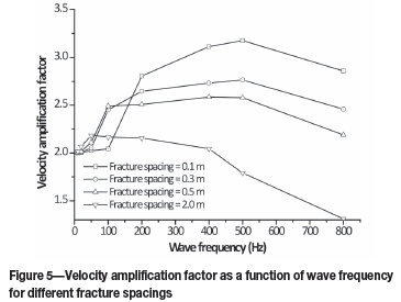
Figure 5 shows the velocity amplification factor as a function of wave frequency for different fracture spacings. The fracture stiffness was 100 GPa/m and the number of fractures in the model was 8. The velocity amplification factor first increases with increasing wave frequency and then reaches a peak value, after which it starts to drop. When the wave frequency falls into the range of 100-500 Hz, the velocity amplification factor has a higher value for each curve except for 2 m fracture spacing. For different fracture spacings, the frequency range changes slightly and shifts toward lower values with increasing fracture spacing. The peak velocity amplification factor is larger for small fracture spacings than that for large fracture spacings. It is also interesting to see that the velocity amplification factor is lower than 2 when the fracture spacing is 2.0 m and when the wave frequency is larger than 400 Hz. In this case, the interaction of waves through fractures is much more complicated and the wave attenuation due to crossing multiple fractures seems to dominate.
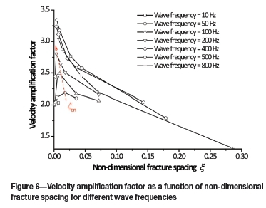
From Figure 6, it is clear that the velocity amplification factor as a function of non-dimensional fracture spacing for different wave frequencies follows the same trend. Due to limited data, the curves do not show any peak when the wave frequency is larger than 200 Hz or lower than 50 Hz. When the wave frequency reaches 500 Hz, the velocity amplification factor is the highest for the same non-dimensional fracture spacing. The critical non-dimensional fracture spacing (ξcri) decreases with the increasing wave frequency. Also, when the non-dimensional fracture spacing is larger than 0.075, the effect of wave frequency on velocity amplification factor becomes less. This conclusion needs to be further validated by adding more data into the curves.
Fracture stiffness
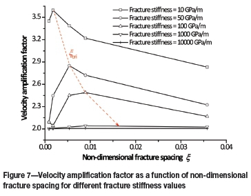
Figure 7 shows the velocity amplification factor as a function of the non-dimensional fracture spacing for different fracture stiffness values. The frequency of the incident wave was set as 100 Hz and the fracture number in the model was 8. It is clear from Figure 7 that the velocity amplification factor decreases with increasing fracture stiffness. The critical non-dimensional fracture spacing (ξcri) increases with increasing fracture stiffness.
Discussion
Wave propagation across fractured rock
When a wave propagates through fractured rock masses, it is often affected by the presence of fractures. Multiple fractures behave as a damper and the wave is normally attenuated. When the fracture spacing is large enough and the wave frequency is high enough, i.e. large non-dimensional fracture spacing ξ,multiple reflections between fractures can be ignored. The wave propagation can be simplified as a short-wavelength problem. The transmission coefficient across parallel fractures is then calculated as a product of the transmission coefficients of individual fractures. The simplified method has been verified by laboratory experiments and it is valid when the first-arriving wave is not contaminated by the multiple reflections (Pyrak-Nolte et al., 1990). However, when ξ is small (low wave frequency and small fracture spacing) the wave superposition caused by inter-fracture reflections becomes strong. The magnitude of the velocity for the transmitted wave in some cases might be higher than that of the incident wave (Zhao et al., 2008). For mining-induced seismicity problems, the rock near the excavation surface is normally fractured due to high in situ or mining-induced stresses. The fracture spacing in general is small and varies from several centimetres to tens of centimetres. The dominant frequency for damaging seismic events varies from several Hertz to several hundred Hertz. The non-dimensional fracture spacing ξ in most cases is small. Therefore, when a seismic wave propagates across a fractured zone near an excavation surface, multiple reflections between the fractures can cause amplification of the particle velocity. Furthermore, when the transmitted wave meets the free surface and reflects back, the amplification of the particle velocity can become even higher.
Interaction of wave and multiple fractures near a free surface
By using a 1D model with a fractured zone simulated explicitly, the interaction of the wave and multiple fractures near a free surface was investigated. The approach adopted in this study was to focus on the velocity at the free end of the 1D model resulting from the superposition of multiple reflected waves, regardless of the detailed process of wave superposition.
The results indicate that the velocity amplification factor is dependent on fracture stiffness, fracture spacing, number of fractures (thickness of fractured zone), and wave frequency. The dependence of the velocity amplification factor on the fracture spacing is governed by the ratio (f) of fracture spacing to wavelength of the incident wave. A critical value (ξcri) is also identified. When ξ < ξcri, the velocity amplification factor increases with increasing ξ. When ξ > ξcri, the velocity amplification factor decreases with increasing f. The critical value (ξcri) increases with increasing fracture stiffness and decreasing number of fractures within the investigated parameter range.
The velocity amplification factor obtained in the analyses shows a higher value when the wave frequency falls into the range of 100-500 Hz. Cichowicz et al. (2000) determined the amplification factors by field measurements in Tau Tona Mine. A strong site effect was revealed by changes in signal properties between hangingwall geophones, exhibiting strong resonances around 160 Hz and in the range 200-300 Hz. Cichowicz (2001) also stated that no resonance was observed in the frequency range 10-100 Hz. Durrheim (2012) concluded that the site amplification factor depends on wavelength, with a maximum amplification factor for a wavelength of about 30 m, which corresponds to the wave frequency of 150-200 Hz assuming a P-wave velocity of 4500-6000 m/s. These observations have been helpful in supporting the conclusion drawn from this numerical modelling study regarding the effect of wave frequency.
The velocity amplification factor decreases with increasing fracture stiffness and approaches 2 when the fracture stiffness is extremely high (10000 GPa/m). The reflection between fractures is strong when the fracture stiffness is low and hence promotes the wave superposition. When the fracture stiffness is high and approaches infinity, the fracture becomes a welded boundary and hence no reflection occurs on the boundary. The fractured zone hence becomes continuous with uniform behaviour and the wave only reflects at the free end with doubled PPV.
Limitation of current numerical modelling
Measurement of seismically-induced ground motion and back-analyses of damaging seismic events have shown that the velocity amplification factor near an excavation surface could be higher than 2. This phenomenon can be attributed to two main effects: structural and site effects. In general terms, the 'structural effect' is controlled by features such as the excavation geometry, regional support systems such as pillars and backfill, bedding plane partings, and the extent of the fracture envelope. The 'site effect' is controlled by local features such as the intensity of fracturing, and the zone of influence of the support elements such as props and packs (Cichowicz et al., 2000). In this study, it is obvious that the structural effect was not considered. Therefore, the results need to be combined with another analysis in order to fully assess the local seismic hazard and rock support performance.
In this study, the fracture deformation is described by a linearly elastic model, which is characterized by constant fracture stiffness. However, laboratory tests have shown that the complete deformation behaviour of rock fractures is generally nonlinear. The fractures near the excavation boundary might not be in close contact, therefore the stiffness could be low when they are initially compressed under compressive seismic wave loading and then increase with the increase of contact stresses. The nonlinear deformational behavior of fractures needs to be further investigated.
Conclusion
In this paper, velocity amplification was investigated by modelling the dynamic interaction between the fractured rock and a free surface using a 1D model. The following important findings were identified.
► The velocity amplification factor, defined as the ratio of wave amplitude at the free end of the 1D model to the incident wave amplitude, can be as high as 3.6
► The wave frequency, fracture stiffness, fracture spacing, and number of fractures (thickness of fractured zone) are the main factors that affected the velocity amplification
► The model results demonstrate that ground motion is strongly influenced by the interaction of a seismic wave with a fracture zone associated with a free surface
► As a consequence the geometrical and mechanical characteristics of the near-surface rock mass of an excavation should be taken into account when assessing its local seismic hazard and rock support performance.
Acknowledgement
This work was financially supported by MIGS II (Mining Initiative on Ground Support Systems and equipment, Series II) consortium and managed by the Nordic Rock Tech Centre AB (RTC), which are gratefully acknowledged. The Centre of Advanced Mining & Metallurgy (CAMM) at Luleå University of Technology is also thanked for supporting the work. LKAB is specially thanked for providing funding for the first author to conduct research on this area.
References
Cichowicz, A. 2001. The meaningful use of peak particle velocity at excavation surface for the optimisation of the rockburst support criteria for tunnels and stopes. Final Report GAP709b, Mine Health and Safety Council, Johannesburg. 33 pp. [ Links ]
Cichowicz, A., Milev, A.M., and Durrheim, R.J. 2000. Rock mass behaviour under seismic loading in a deep mine environment: implications for stope support. Journal of the South African Institute of Mining and Metallurgy, vol. 100. pp. 121-128. [ Links ]
Durrheim, R.J. 2012. Functional specifications for in-stope support based on seismic and rockburst observations in South African mines. Proceedings of the Sixth International Seminar on Deep and High Stress Mining. Perth, Australia, 28-30 March. Potvin, Y. (ed.). Australian Centre for Geomechanics, Perth, Australia. pp. 173-187. [ Links ]
Durrheim, R.J., Kullmann, D.H., Stewart, R.D., and Cichowicz, A. 1996. Seismic excitation of the rock mass surrounding an excavation in highly stressed ground. Proceedings of the 2nd North American Rock Mechanics Symposium, Montreal, Quebec, Canada, 19-21 June. Aubertin, M., Hassani, F., and Mitri, H. (eds.). Balkema, Rotterdam. pp. 389-394. [ Links ]
Gu, J. and Zhao, Z.Y. 2009. Considerations of the discontinuous deformation analysis on wave propagation problems. International Journal for Numerical and Analytical Methods in Geomechanics, vol. 33. pp. 1449-1465. [ Links ]
Hildyard, M.W. 2007. Wave interaction with underground openings in fractured rock. Rock Mechanics and Rock Engineering, vol. 40. pp. 531-561. [ Links ]
Kaiser, P.K., McCreath, D.R., and Tannant, D.D. 1996. Canadian rockburst support handbook, Geomechanics Research Centre, Sudbury. 300 pp. [ Links ]
Kuhlmeyer, R.L. and Lysmer, J. 1973. Finite element method accuracy for wave propagation problems. Journal of the Soil Mechanics and Foundations Division (American Society of Civil Engineers), vol. 99, no. 5. pp. 421-427. [ Links ]
Linkov, A.M. and Durrheim, R.J. 1998. Velocity amplification considered as a phenomenon of elastic energy release due to softening. Proceedings of the Third International Conference on Mechanics of Jointed and Faulted Rock, Vienna, Austria, 6-9 April. Rossmanith, H.P. (ed.). Balkema, Rotterdam. pp. 243-248. [ Links ]
MCGARR, A. 1997. A mechanism for high wall-rock velocities in rockbursts. Pure and Applied Geophysics, vol. 150. pp. 381-391. [ Links ]
Malmgren, L. and Nordlund, E. 2008. Interaction of shotcrete with rock and rock bolts-a numerical study. International Journal of Rock Mechanics and Mining Sciences, vol. 45. pp. 538-553. [ Links ]
Mikula, P.A. 2012. Progress with empirical performance charting for confident selection of ground support in seismic conditions. Mining Technology, vol. 121, no. 4. pp. 192-203. [ Links ]
Milev, A.M. and Spottiswood, S.M. 2005. Strong ground motion and site response in deep South African mines. Journal of the South African Institute of Mining and Metallurgy, vol. 105. pp. 515-524. [ Links ]
Ortlepp, W.D. 1993. High ground displacement velocities associated with rockburst damage. Rockburst and Seismicity in Mines. Proceedings of the 3rd International Symposium on Rockbursts and Seismicity in Mines, Kingston, Ontario, Canada, 16-18 August. Young, P.R. (ed,). Balkema, Rotterdam. pp. 101-106. [ Links ]
Potvin, Y., Wesseloo, J., and Heal, D. 2010. An interpretation of ground support capacity submitted to dynamic loading. Mining Technology, vol. 119, no. 4. pp. 233-245. [ Links ]
Pyrak-Nolte, L.J., Myer, L.R., and Cook, N.G.W. 1990. Transmission of seismic waves across single natural fractures. Journal of Geophysical Research, vol. 95, no. B6. pp. 8617-8638. [ Links ]
Roberts, M.K.C. and Brummer, R.K. 1988. Support requirements in rockburst conditions. Journal of the South African Institute of Mining and Metallurgy, vol. 88, no. 3. pp. 97-104. [ Links ]
Stacey, T.R. and Rojas, E. 2013. A potential method of containing rockburst damage and enhancing safety using a sacrificial layer. Journal of the Southern African Institute of Mining and Metallurgy, vol. 113. pp. 565-573. [ Links ]
Wagner, H. 1984. Support requirements for rockburst conditions. Proceedings of the 1st International Symposium on Rockbursts and Seismicity in Mines. Gay, N.C. and Wainwright, E.H. (eds.). South African Institute of Mining and Metallurgy, Johannesburg, South Africa. pp. 209-218. [ Links ]
Yi, X.P. and Kaiser, P.K. 1993. Mechanisms of rockmass failure and prevention strategies in rockburst conditions. Proceedings of the 3rd International Symposium on Rockbursts and Seismicity in Mines, Kingston, Ontario, Canada, 16-18 August. Young, P.R. (ed.). Balkema, Rotterdam. pp. 141-145. [ Links ]
Zhao, X.B., Zhao, J., Cai, J.G., and Hefny, A.M. 2008. UDEC modelling on wave propagation across fractured rock masses. Computers and Geotechnics, vol. 35. pp. 97-104. [ Links ]
Paper received Oct. 2014
Revised paper received Jun. 2015.

