


Serviços Personalizados
Artigo
 Inglês (pdf)
 Artigo em XML
 Referências do artigo
Indicadores

Links relacionados
-
 Citado por Google
 -
 Similares em Google
Compartilhar

 Permalink
Journal of the Southern African Institute of Mining and Metallurgy
versão On-line ISSN 2411-9717
versão impressa ISSN 2225-6253
J. S. Afr. Inst. Min. Metall. vol.115 no.11 Johannesburg Nov. 2015
http://dx.doi.org/10.17159/2411-9717/2015/v115n11a5
SURFACE MINING CONFERENCE PAPERS
Mining complex geology, mitigation of float dust, and developing autonomous machine capability using horizon sensing technology for coal seam boundary detection
J. Duncan; L.G. Stolarczyk
Stolar Global Mining, Raton, New Mexico, USA
SYNOPSIS
Long before the environmental movement, coal miners were suffering from occupational diseases that became apparent in the later years of service, and especially during the retirement years. Chronic exposure to micro-fine dust in the respirable range ('float' dust) causes various lung diseases, referred to as coal mine dust lung disease. In the USA alone, 76 000 miners have died of coal mine dust lung disease since early legislation recognized the issue in 1969. Researchers believe that reducing float dust exposure limits alone will not reverse the increasing incidence of coal mine dust lung disease seen in the current generation of miners. Trace and radioactive metals are concentrated in the thin boundary layers of the coal seam (Roberts, 2013), and hence float dust includes silica and toxic trace metals. The production and quality of coal is also significantly impacted by the presence of these contaminants in the coal. In the combustion process, the trace metals are oxidized and become incorporated in the fly ash and flue gas. Since they are extremely water-soluble, they represent a significant danger to health and the environment. Coal preparation plants and power stations need to mitigate these contaminants as far as is practical, but the simple fact is that most contaminants should have been left un-mined.
This paper describes an innovative coal-cutting solution to the longstanding technology gap in mining - the ability to measure uncut coal layer thickness to the boundary rock layer. Because of constant changes in geology, seam thickness, and seam undulation, the horizon sensor must be located in the bit-block of the rotating cutter drum of the mining machine. Contaminants in ROM coal must be minimized at the source - that is, at the rock/coal crushing cone directly under the bit-tips of the cutting drum. Bittip distances to the rock boundary layer must be automatically controlled in real time when mining in a complex and undulating coal bed. Horizon sensing (HS) technology enables the mining machine's cutting picks to stop at a specified distance from undulating horizons of the boundary rock. The thin contaminated coal layer can be left in situ, significantly reducing the toxicity of the float dust. Preventing the metal picks from striking quartz-containing boundary rock also reduces the occurrence of methane ignitions. HS technology equipped with pick force vector sensing can allow optimization of the cutting pick lacing pattern for minimum coal and rock crushing, thereby reducing float dust. This technology may enable the mining industry to convert from automated machine control to autonomous during coal cutting and loading.
Keywords: coal mining, float dust, longwall shearer, horizon sensing, selective cutting, automation, health and safety
Introduction
The 1999 vision statement developed by the Chief Executive Officers of the National Mining Association (NMA) for the Mine of the Future (MOF) and their prioritized Technology Development Road Map, together with a 2010 Section 11 National Research Council/National Engineering Academy Study, confirmed that boundary detection in coal and metal/non-metal mining remains a mining technology gap. The National Aeronautical and Space Administration (NASA) Automated Coal Extraction (ACE) programme determined in 1971 that a horizon sensor (HS) installed on a rotating coal cutting drum and geological vision ahead of mining technologies were beyond the state-of-the-art.
Remote control of mining machines assisted by 'last cut' machine control algorithms has enabled machine operation from a distance. The technology, when augmented with helmet-mounted air filters, has significantly improved machine operator health and safety.
In idealistic coal deposits without meandering paleochannels, faults, and other types of anomalous seam geology, the prevailing state-of-the-art is highly useful. In the real world of sedimentary deposits, meandering paleochannels and differential compaction cause seam rolls, floor 'horsebacks', rapidly-thinning coal seams, and fractured roof rock. Paleochannels, faults, and dykes cause very high nonlinear stress fields in the seam and boundary rock. The thin boundary layers of a coal seam are commonly contaminated by heavy metals and radioactive elements that precipitate by biochemical reduction during the deltaic or strandline peat-coal forming processes. Gradational deposition is partly responsible for the higher density, sulphur, and ash observed in the thin boundary layer (Chyi and Chou, 1986). Researchers now believe that heavy metals in the cutting dust plume are a contributing factor in lung disease. These considerations are drivers for leaving the thin contaminated boundary layers behind in the mine. Additional arguments can be made that the horizon sensing hardware must be mounted on the rotating coal-cutting drum to look upward and forward for abandoned hydrocarbon well casings (the cause of the Farmington Mine explosion), loss of hydraulic pressure in the roof support canopy (the cause of the San Juan Mine fire), and abandoned mine entries (the cause of the Quecreek Mine water inundation).
Coal boundary geology impacts health, safety, and productivity
Most likely, coal seams were originally lenticular deposits with smoothly changing thickness. However, the seams have been affected by tectonic events over time and have been deformed considerably. The common deformations of coal seams induced by earth movements include severe undulations, sandstone intrusions, faults, and sudden thinning, which change the shape and location of the boundaries between the coal seam and the roof and/or floor rocks. Geological exploration in advance of mine development can identify some of the deformations, but the large spacing between the exploration drill-holes or data-points makes detection of localized (and very often more severe) deformations impossible. These undiscovered deformations often cause significant operational difficulties and economic losses. There are numerous cases where such localized and severe deformations have forced the abandonment of large underground coal reserves and developed longwall panels. To avoid cutting into the seam boundary rock in the case of a meandering paleochannel seam roll, the machine's automated cut algorithm must begin at the downward floor cut ahead of the paleochannel margin to safely mine through a differentially compacted seam anomaly. The 'last cut memory' horizon control algorithms are not useful for automated control of shearers in an undulating seam environment. In geologically disturbed environments, the shearer operator needs to be within visual range of the machine.
Complex geology and stratified contaminants
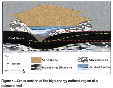
Figure 1 illustrates a cross-section of the high-energy cutbank region of a paleochannel. The red dashed line indicates extracted coal roof and floor horizons where the machine operator controls the vertical cut by observation of the bedding plane 'marker bands'. On approach to seam disturbances caused by a paleochannel, the marker bands vanish and the machine cuts through the contaminated coal layer and sandstone intrusion. The yellow dashed line illustrates the cut when the machine automation includes HS.
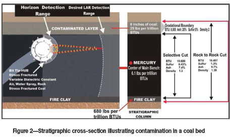
Because of microbial processes occurring during the seam deposition (strandline, fluvial, or deltaic), the thin seam boundary coal layer is contaminated with biochemically reduced forms of heavy metals. Figure 2 illustrates the physical, chemical, and thermal properties of a typical strati-graphic section within a coal seam and provides a layered breakdown of contaminants such as mercury, ash, and sulphur (Chyi and Chou, 1986).
Heavy metals and quartz in respirable dust cause lung disease. Researchers now realize that lung disease may be caused by heavy metals, as well as silica dust reactions, which diminish the rate of oxygen transfer from lung tissue into the bloodstream.
A serious environmental threat to the mining industry is legislation declaring boiler fly ash toxic because of the re-oxidation of heavy metals in the combustion process. From a health and safety point of view, thin contaminated boundary coal layers should be left behind in the mine.
Coal workers' pneumoconiosis (CWP) is one of the worst diseases among coal miners. The recent increase in CWP cases in the US coal industry makes dust control in underground coal mines imperative. Preventing the cutting bits of the mining machine from mining into hard rock containing quartz is one of the most important dust control strategies employed in coal mining operations, and can greatly benefit miners' health and safety. Real-time detection of the shape and location of the boundary between the coal seam and the hard roof and floor rocks in localized deformations in advance of the mining machines is the most effective way to eliminate sparks and quartz dust.
More immediate to miners' safety, cutting the severely deformed coal seams without detailed knowledge of the deformation boundaries present could affect roof conditions and the explosiveness of the mining environment. For example, mining machines cutting into unexpected hard roof or floor rocks, such as sandstone, can produce incendiary sparks with more than 0.25 mJ of energy, capable of igniting methane and then coal dust. The ignition source for the Upper Big Branch (UBB) mine explosion was longwall shearer bits cutting into hard rock. Sparks generated by cutting into quartz-containing hard rock in US coal mines have caused numerous unreported short-duration methane flames that did not develop into explosions or large fires due to insufficient methane and coal dust present in the working space. However, the most important aspect of preventing fires and explosions in underground coal mines is to eliminate the ignition sources, and cutting sparks are the most difficult ones to prevent. Avoidance of cutting quartz-containing hard roof and floor rock is an effective way to prevent cutting sparks.
From a theoretical point of view, the 'float' dust associated with the bit-tip crushing of coal and rock must have been the 'technical root cause' of the UBB mine accident. Reading the UBB accident report from an engineering and applied science perspective, rather than a regulatory point of view, leads to following questions:
(1) Where did the 'float coal' fines come from?
(2) Why did the autopsies report that the victims were suffering from various stages of lung disease?
(3) Why were the pick and bit blocks excessively worn?
(4) What caused the ignition of methane on the face?
To combat the 'float' coal dust problem, the bit tip vector force and bit-block lacing pattern can be optimized for minimum coal dust generation only if horizon sensing and vector force data are captured and analysed by the mining machine in real time. All of the above questions, when discussed in an engineering and applied science-based forum, define the design specifications for coal seam boundary detection that will significantly improve mining health and safety.
Formation and alteration of coal deposits
Advances in mine health and safety depend on knowledge of the gechemistry, biology, and the radio-geophysics of the peat-coal forming environment. Coal beds are formed in different sedimentary environments. The most common are deltaic and strandline deposits of a transgressing sea. Lagoons form behind coastal barriers and inland lakes contain nutritious floor sediments ('fire clay') that support vegetation. The marine and littoral environments are sources of large quantities of sodium, chlorine, magnesium, potassium, and sulphur (Chyi and Chou, 1986). Magnesium, iron, and calcium may be trapped in coal as carbonates, although generally seawater does not introduce much iron or calcium. Much of the liquid contamination is squeezed out of the coal as it is compacted and the rank increases. Peat-coal deposits form in the delta swamp regions of river systems. The upper floodplain, mud-water flow, and the subsiding delta regions of a river system are illustrated in Figure 3.
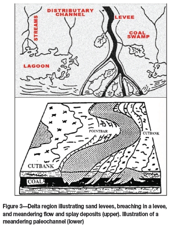
Frequently, sequences of dry and wet periods during burial create a gradational coal seam boundary layer with higher ash density increasing from a mid-seam value of 1.3 to 1.4. Continuing argillaceous mudflow forms roof-rock sealing shale and mudstone layers, which are impermeable. In deltaic deposits, flooding through breaches in the levees creates porous sandstone paleochannels that meander in the sedimentary layers surrounding the coal seam. Deltaic deposits typically have a contaminated layer at the top of the coal layer. Often, the high-energy 'cutbank' or erosional component of a paleochannel scours into the coal layer, replacing coal with porous quartzite sandstone paleochannels as illustrated in Figure 3.
Upper floodplain argillaceous mud-water flows into the peat-coal swamp carrying oxides of trace elements. Vegetation grows in the swamp region of the delta, forming peat-coal. During the time sequences of mudflow, deposition, and subsidence of the delta region peat-coal swamp, the environment of the upper layer of peat-coal changes to an oxygen-deficient, reducing condition. Acclamation of anaerobic bacteria creates a reducing environment. Some elements precipitate when encountering a reducing environment in the swamp contaminating the upper peat-coal layer. Pyrite in coal typically forms from hydrogen sulphide and iron and involves the bacterial reduction of sulphates to hydrogen sulphide at pH values of 7 to 4.5, followed by combining of hydrogen sulphide, elemental sulphur, and ferrous oxide to form pyrite and water. The sulphate source may be seawater or vegetation. Subsequent burial and compaction greater than 5:1 forms a thin boundary layer of coal contaminated with pyrite, sulphur, and heavy metals such as mercury, uranium, arsenic, and radioactive potassium (K34). The ensemble of these contaminates is called ash (Chyi and Chou, 1986).
Coal seam microstructure and gas flow
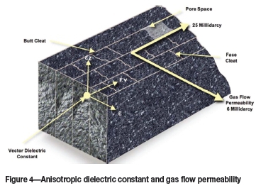
Differential compaction occurs in the stratified rock and coal layers, resulting in fracturing, rolls, and rapid thinning of the coal bed. The coal layers illustrated in Figure 4 exhibit face and butt cleat structure, which significantly impacts gas flow permeability and differential stress within the coal seam (Bausov and Stolarczyk, 2007). This anisotropy in the physical microstructure of the coal results in anisotropy of its electrical properties such as dielectric constant, an important variable in remote sensing and radiowave imaging.
One of the important characteristic of coal is its microporous and highly fractured nature, which plays an important part in many of the physiochemical properties of coal, such as methane gas retention capacity and highly adsorbing and absorbing properties. Trapped methane gas is released during the mining process when the coal is fractured and the micropores open, allowing transport of gas to the atmosphere, and chemically adsorbed gas becomes available for liberation into the microporous structure or fracture system. The flow of gas stored in the microporous structure is governed by Flick's Law. The free gas in the fracture system flows according to Darcy's law. These two modes of transport are interdependent. The physics of gas in coal during mining is complex and conventional gasfield methods of reservoir engineering analysis are not applicable.
The internal surface area of coal can be as high as 3x 109 cm2 per kilogram of coal, and 0.022 standard cubic metres of methane per kilogram of coal can be adsorbed on the internal surface area at the saturation pressure of over 10 000 kPa. Depending on the rank of the coal and integrity of the overburden, the amount of methane adsorbed and absorbed can reach as high as 28 times the volume of coal. Each kilogram of coal fuels the generation of 8000 kJ of electric power in a typical coal-fired power plant.
At atmospheric pressure, the most explosive concentration of methane in air is 9.5% by volume. Methane also has a tendency to stratify and form horizontal layers near the roof of mine workings where the ventilation velocities are too low to prevent layering. This phenomenon occurs because methane has a density of only 0.55 that of air. In many instances, a ventilation air velocity of 0.5 m/s will prevent layering, but in some circumstances this air velocity will be insufficient as barometric pressure decreases. These changes are created by approaching storm fronts, decreasing barometric pressure as they pass.
Charles Mcintosh of Eastern Illinois University conducted the earliest detailed study of methane gas in coal seams in the late 1950s. The rate of gas liberation during coal mining depends upon the age, depth, and structure of the coal seam; the mining technique; and the rank of the coal (the higher the fixed carbon content of the coal, the higher the methane liberation). Geologically induced nonlinear stress fields create fractures, which along with the cleats, form pathways for gas and water movement through the coal matrix. Cutting machines are oriented to cut (fracture the coal) at an angle to the butt cleats to maximize roof-rock stability. The anisotropic gas-flow permeability is maximized when horizontal production wells are drilled such that long face cleats drain gas and water into a well.
Adsorbed (i.e., bound to the matrix, approx. 67%), absorbed (pressurized cleat volume, approx. 27%), and microfracture (free, approx. 6%) methane gas concentrations range up to 62 m3/t, with a typical value being about 22 m3/t. The coal seam water content resides in fractures and the cleat structure. During degassing, water is pumped from the well to reduce pressure and facilitate gas flow. There is a thermodynamic mass transfer problem that suggests acoustic stimulation may increase the gas flow permeability. Frequently, argillaceous cuttings or drilling mud 'cake' the walls of the drill-hole, decreasing gas flow permeability. Acoustic stimulation within degasification boreholes increases gas flow permeability by a factor up to three. Acoustic stimulation ahead of high-production-rate longwalls will increase the degassing rate and reduce the potential for methane ignition, especially if water is injected into the acoustically enhanced permeability of the borehole walls. The shale and mudstone layer bounding the coal seam seals the coal bed from nearby porous sandstone freshwater aquifers. The sealing layer of a coal bed is frequently scoured by an overlying sandstone paleochannel, which creates a dangerous margin of weak rock.
Layered coal deposits form natural electromagnetic and seismic waveguides
Increasing moisture in the coal cleats increases both the dielectric constant and electrical conductivity of the coal layer. The anisotropic dielectric constant of the cleated coal depends on the polarization of ions, sourced from the argillaceous minerals, in the pores of the cleat. The electric field component of an electromagnetic (EM) wave may cause differing polarization of asymmetrically charged molecules between the face and butt cleat structure, creating an anisotropic dielectric constant. The bedding plane is orthogonal to both the face and but cleat structure. The relative dielectric constant of mid-seam coal is near 4. The relative dielectric constant is in the vertical direction and is also near 4, except near the seam boundary. The thin boundary layer frequently has a higher ash content, increasing the relative dielectric constant toward 9.
The bedding planes are oftent observable in the ribs of recently cut coal and are used as visual 'marker bands'. Machine operators use these marker bands in an attempt to visually control the roof and floor cutting horizon of the advancing machine. Visual guidance avoids cutting through the contaminated boundary layer and into quartz-containing boundary rock. The marker bands often vanish on approach to a geologic disturbance, such as a paleochannel or fault zone, or are obscured by cutting 'float' dust plumes. The bedding plane can form because of ash plumes from volcanic eruptions settling over the peat-coal region and changes in the peat-coal depositional environment. The mudstone and shale sealing layer has an electronic charge density and electrical conductivity that are several orders of magnitude greater than the mid-seam coal layer. The conductivity and dielectric contrast form a natural waveguide for transmission of quasi-transverse electromagnetic (quasi-TEM) waves. One of the EM wave theory boundary conditions requires that the electric field (E)components of the travelling quasi-TEM wave be vertically polarized and terminate on the mobile negative charge in the roof boundary rock and begin on the positive charge in the floor rock, as illustrated in Figure 5.
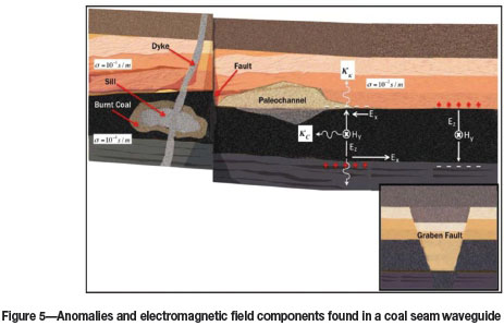
The quasi-transverse EM seam wave (quasi-TEM) electric field component, E,is polarized in the vertical direction and the magnetic field component (Hy)is polarized horizontally in the seam. The energy in this part of the EM wave travels laterally in the seam from the transmitter to a companion receiver. There is a horizontally polarized electric field component (Ex)that has zero value in the centre of the seam and reaches a maximum value at the interface between the sedimentary rock and coal. Because of the boundary charge illustrated in Figure 5, the Exand Hy components are responsible for transmission of the EM wave signal into the boundary rock layer. The energy in this part of the EM wave travels vertically and out of the coal bed (i.e., the coal seam is a 'leaky waveguide'). However, the transmission of low- and medium-band frequencies 'trapped' within the coal seam waveguide has been used to detect and image geologic disturbances like those seen in Figure 5.
Energy in the EM wave 'leaks' into the fractured rock overlying the seam, increasing the absorption rate. Thus, weaker roof rock can be detected by mapping rapid increases in attenuation rate (i.e., gradient) across the plan view of the seam, including the developed entries. Fractures in the boundary layer will increase the roof fall hazard (see Figure 1).
Due to the EM waveguide behaviour, the magnitude of the seam radiowave decreases due to absorption because of two different factors, namely the attenuation rate and cylindrical spreading of wave energy in the coal seam.
The cylindrically spreading factor is independent of the conductivity of coal and is mathematically given by 10 log r, where r is the distance in metres from the transmitting to the receiving antenna. This factor compares with the non-waveguide far-field spherically spreading factor of 20 log r. Thus, at 100 m, the magnitude of the EM wave within the coal seam decreases by a factor of only 10 in the waveguide and by a factor of 100 in an unbounded medium. An advantage of the seam waveguide is greater travel distance. Another advantage is that the travelling EM wave remains predominantly within the coal seam waveguide (i.e., the coal bed), except when the sealing mudstone or shale laver is fractured by an overlying paleochannel. Because energy transmission is primarily within the coal bed, seam anomalies can be detected with radio imaging method (RIM) reconnaissance (i.e., cross-panel direct ray) and tomography scans.
Tomographic mapping of paleochannels ahead of mining can locate where ground control should be intensified by roofbolting and installing screening and/or trusses. Frequently, the roof rock fails when entries are driven under margins of paleochannels. Roof-fall injures will be reduced significantly when images of margins are mapped and ground control measures are intensified. Measuring the Hyfield component will increase mine safety by locating paleochannels crossing an entry. Over 500 longwalls have safely mined through these anomalies with the assistance of RIM transmission tomography (Stolarczyk, 2010).
Detection of acoustic and seismic waves
The acoustical (pressure wave) resonance of the coal seam depends on seam thickness and is typically in the region of 760 Hz. High nonlinear stress fields in the coal bed and surrounding rock can be measured with suitable instrumentation and provide additional information for mining safety purposes. Double-sideband acoustic waves are heterodyned (i.e., generate sum and difference frequencies) when transmitted through nonlinear stress fields (Stolarczyk, 2010). Detection of the heterodyne frequencies can be useful in the in situ mapping of stress fields when pulling pillars in the coal extraction process. Seismic wave reflection and transmission in the coal seam waveguide have been used to detect and image anomalous geologic structures. The wave velocity is near 4000 m/s in the seam-bounding rock layers, decreasing to 2500 m/s in the coal seam. The reflection method has proven to be effective in detecting full-seam faults ahead of mining.
Seismic imaging was developed to detect and map geologic structure in coal beds. A seismic source applied on the rib initiates both pressure (P) and shear (S) waves that propagate in the coal seam because of contrasting acoustic impedance between the boundary rock and coal. The propagation velocity is approximately 4000 m/s in rock and 2500 m/s in coal. Most of energy propagates in the rock layers, and not in the seam as in the EM case. Seismic imaging is based on reflections from boundaries of contrasting acoustic impedance. The detection and imaging method is highly successful in detecting full-seam vertical faults, but is problematic in detection of partial seam disturbances, such as scouring paleochannels.
Gamma and electronic charge emissions from floor and roof rock
The river argillaceous mud-flow contains radioactive potassium (K34). Higher concentrations are found in shale, mudstone, and slate seam boundary rock, with 40 to 60 emissions per second in boundary rock compared to less than 20 per second in the coal bed. Because coal is a gamma-absorber, the boundary detection distance is limited. Bursts of gamma emissions occur when the boundary rock is crushed by a pick. Gamma emissions from sandstone paleochannels are very low, causing an automated mining machine to lose horizon control when most needed. Quartz crystals are piezoelectric and generate bursts of electrical charge with changes in pressure along their axes. Crushing hard rock containing piezoelectric quartz generates electromagnetic radiation.
The solution - a smart coal-cutting drum
Historical horizon sensor development
Driven by many observations made at the Miners' Colfax Medical Centre in Raton, New Mexico, of coal miners retiring from service and then undergoing a slow smothering death, a revolutionary horizon sensor development and in-mine demonstration programme was initiated in 1960. The 54-year research and development phase of the HS product lifecycle began with NASA Johnson Space Centre funding to develop a sensor to measure, in real time, the thin ice layer build-up on the liquid fuel tanks on the Space Shuttle booster rocket prior to launch, which was the 'technical root cause' of the Columbia Shuttle re-entry disaster. The US Department of Energy (DOE) Mine of the Future (MOF) programme, responding to the technology roadmapping work undertaken by the National Mining Association (NMA), achieved prototype validation of the HS technology at a cost of approximately $1 million. Internal corporate funding totalling nearly $10 million achieved prototype demonstrations of the HS technology in a mining environment.
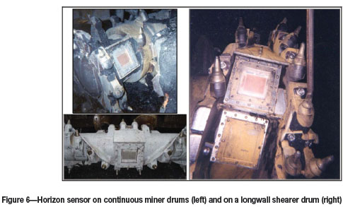
Many mining companies participated in the installation, demonstration, and assessment of HS performance on 20 coal-cutting drums, six of which were high-production-rate longwall mining systems. Shock and vibration levels were measured in real time and found to average 26G and to reach peak force levels of 100G (Duncan, 2004). Sandia National Laboratories (SNL) assisted in the development of high-, low-, and band-pass mechanical filters installed in the Mine Safety and Health Administration (MSHA) approved flameproof enclosure. The enclosure endurance of more than 18 months was validated at a maximum shock and vibration level by SNL. The mining company's in-mine demonstration expenses were not accurately determined; however, a conservative estimate is of the order of $200 000 per installation. The Consol in-mine HS demonstration on the Robertson Run Coal Mine longwall shearer was directed and independently evaluated by Consol's technical team. In-mine demonstrations were also conducted by Interwest Mining and Blue Mountain Energy at the Deserado Mine, confirming that rotating shearer drum pick dust, ignition control water spray, and pick fracturing changed the dielectric constant of the thin fractured coal layer, resulting in coal thickness calibration problems (Duncan, 2004). The HS development and evaluation team determined that a technical solution was well beyond the state-of-the-art for ground-penetrating radar (GPR) technology. At that point, the HS programme was halted and the research phase investment continued with the goal of solving the calibration problem caused by the varying relative dielectric constant of the bit-fractured coal layer. During the development of these various sensor platforms, a number of patents were issued to the HS's instrumentation and methods of operation. Photographs of various HS installations are shown in Figure 6 (continuous miner and longwall shearer).
Advanced horizon sensor capabilities
A state-of-the-art radar technology was developed to combat the calibration problem and demonstrated in the Consol and Oxbow coal mines (Duncan, 2004). This work solved the problematic geologic clutter (rapid spatial change in dielectric constant) and very high reflection in the 'early arrival time' EM field components that engulf the 'late arrival time' EM field components reflected from the coal-rock interface and air- or water-filled abandoned entries.
The double-sideband gradiometer (DSBg) GPR technology was developed initially under the NMA/DOE MOF programme. Initial trials on a highwall mining machine and horizontal drill string navigation collar enabled distance determination relative to the seam boundary. With internal and demonstration funding from DOE, the DSBg GPR resulted in a validated prototype in the mining environment. The DSBg GPR was successfully developed for detection of abandoned mine entries with funding provided by the MSHA (Stolarczyk, 2010). The six-year development of a spatial clutter and reflection elimination (SCARE) functionality may have overcome the horizon sensor calibration issue observed in most of the HS demonstrations.
The SCARE functionally was developed to suppress the 'early arrival time' (EAT) cluttering reflection from the pick-fractured coal layer and detect the 'late arrival time' (LAT) EM field components reflected from the coal-rock interface and even a gradational boundary. The double-sideband gradiometer (DSBg) GPR with SCARE functionality suppresses the 'early arrival time' EM wave field components (ER1) by up to 70 dB relative the 'late arrival time' field components (ER2) from the coal-rock boundary interface (see Figure 7) (Stolarczyk, 2010).
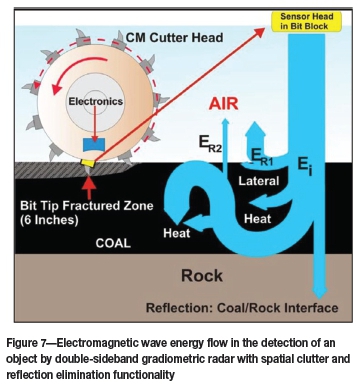
The suppression depth can be selected by the adjusting the modulation frequency, which is one-half of the doublesideband frequency separation. The fracture suppression depth is approximately equal to the pick length. By including a bit force vector sensor in the bit block, the interface pick rock boundary intersection can be determined to provide the calibration needed in an automated machine to control rock cutting depth and to acquire data for bit lacing to minimize the production of fines. The K34 gamma emission burst generated when the pick strikes the argillaceous boundary can be detected by a gamma radiating sensor built into the electronics. Quartz radiation emitted when boundary rock is crushed may also be used to detect the boundary rock interface.
It is often necessary to cut through the contaminated coal layer and into boundary rock to allow machine clearance. Bit blocks with piezoelectric sensors have been designed to measure the bit tip force vector and can determine when the bit intersects the rock interface. The rock cut depth can be accurately controlled by the automation of the machine.
Dust produced by cutting drums is generated from rock and coal that is crushed directly under the individual bits on a rotating cutter head. The pick tip angle of attack, bit penetration, and drum lacing pattern affect the generation of fines and dust. A pick bit block, instrumented with piezoelectric sensors, was developed in the NMA/DOE/MOF programme in partnership with Colorado School of Mines (CSM) engineers and trialled in their pick cutting force measuring apparatus. The objective of the work was to measure the pick vector force angle in real time. The work suggested that reducing the number of picks on the drum and increasing the spacing of the picks on the bit block would reduce the production of fines and dust.
There are a number of patents that claim dust and fines reduction methods (e.g., very smooth drum surfaces and shaped picks). Coal fracturing is dependent on the cleat geometry and micro-fractures induced by horizontal stresses relative to the vector pick force angle and propagating fracture angle. Coal fines generation is reduced when the next pick intersects the propagating fracture. Measurement of vector pick angle and uncut coal thickness data can be transmitted by radio modem to the shearer.
The DSBg GPR with SCARE functionality will have the capability of looking up through uncut coal to detect longwall roof supports that have lost hydraulic pressure, and of looking forward to detect abandoned hydrocarbon well casings. The multiple-mode smart coal-cutting drum data can be transmitted from the rotating drum to the mining machine and processed. The acquired data enables optimization of coal cutting for minimum fines generation.
Practical horizon sensor requirements
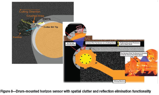
Advancement in the automation of coal-cutting machines will benefit miner health and safety. Figure 8 shows the integration of the RMPA sensor into the bit block. The rotating cutting drums of continuous and longwall shearers rotate at one revolution per second. The RMPA bit block sensor has a 17-millisecond window to measure the thickness of uncut roof and floor coal. The bit tip fractured zone illustrated in Figure 7 exhibits a varying relative dielectric constant, which causes the cluttering reflected EM wave field components to vary in magnitude.
Data processing software for determining the bit block lacing pattern will require bit pick vector force measurement and filtering (i.e., Fourier and Laplace transform analysis) between the time and frequency domains of the pick force sensing signal. The nonlinear stress fields and fractures in the coal layer cause the 'strained' pick to instantaneously release energy, creating heterodyne acoustic band frequencies signals that must be processed to determine the direction cosines of the pick vector force. The pick intersection with the coal-rock interface must be determined to achieve self-calibration of the uncut coal layer thickness measured by the HS, and the required depth of cut into the rock for machine clearance.
The RMPA sensing and DSBg GPR with SCARE functionality enables automation of the machine cut so that the operator can be out of the 'float' dust plume. The DSBg GPR with SCARE provides a signal-to-clutter (S/C) ratio of 13 dB. Conventional GPR cannot provide an S/C above -11 dB. Therefore to solve the technology gap that exists in horizon sensing technology, conventional RMPA and GPR technology needs to be replaced with DSBg with SCARE functionality, and smart pick sensors implemented.
Concluding remarks
Coal fuelled the industrial revolutions in the UK and the USA and is doing so in the rapidly developing countries. World coal production is 10 billion short tons per year. Environmental regulations have caused a rapid decline in US coal demand, resulting in domestic production falling below one billion tons per year. China is increasing coal production above four billion tons per year, taking economic advantage of lower energy costs while creating enormous manufacturing wealth. Coal beds exhibit stratified layers contain reduced forms of heavy metals that when burned in boilers become oxidized in the fly ash. Even though the modern Chinese boilers produce far less gaseous emissions and ash than boilers manufactured decades ago, the toxic oxidized forms of heavy metals are soluble, making them mobile in the environment. The heavy metals found in fish suggest that the world's oceans and river systems are being contaminated in the process of wealth creation. Even if US coal production is shut down, worldwide environmental contamination will not change as world demand for coal-fired energy is increasing faster than the US shutdown rate.
There are 500 underground coal mines in the USA. Assuming there are three continuous mining (CM) machines in each mine, the total number of CM machines with cutting drums operating in the USA becomes 1500. Assuming that the rest-of-the world market is twice the size of the US market, the worldwide total is 4500 cutting drums requiring advanced HS functionality. This advanced horizon sensing technology must be an advanced radar device (HS-Radar) to combat the known limitations of the current technology. The HS-Radar will have a dramatic and positive impact on the health and safety issues associated with dust, contaminants, and ground control hazards for all coal miners.
References
Bausov, I. and Stolarczyk, L. 2007. Look-ahead radar and horizon sensing for coal cutting drums. 4th International Workshop on Advanced Ground Penetrating Radar, Naples, Italy, 27-29 June 2007. Soldovieri, F., Crocco, L., and Persico, R. (eds.). IEEE, New York. [ Links ]
Chyi, L.L. and Chou, C-L. 1986. Geochemical characteristics of the Springfield Eastern Kentucky No. 9 Coal in Western Kentucky. Special Paper 248. Geological Society of America, [ Links ]
Duncan, J. 2004, Horizon Sensor Demonstration Program at TOvCC, Final Report. Project Number D-01-19. Ohio Coal Development Office, Columbus, Ohio. SH-2004-03-OCCT-FR. [ Links ]
Roberts, P. 2013. Coal is toxic. Greens Mining, Australia. [ Links ]
Stolarczyk, L.G. 2010. Double sideband suppressed carrier radar to null near field reflections from a first interface between media layers. US Patent 7,656,342 B2. [ Links ]
This paper was first presented at the, Surface Mining 2014 Conference, 16-17 September 2014, The Black Eagle Room, Nasrec Expo Centre, Johannesburg, South Africa.

