


Services on Demand
Article
 English (pdf)
 Article in xml format
 Article references
Indicators

Related links
-
 Cited by Google
 -
 Similars in Google
Share

 Permalink
Journal of the Southern African Institute of Mining and Metallurgy
On-line version ISSN 2411-9717
Print version ISSN 2225-6253
J. S. Afr. Inst. Min. Metall. vol.115 n.10 Johannesburg Oct. 2015
http://dx.doi.org/10.17159/2411-9717/2015/v115n10a2
Friction processing as an alternative joining technology for the nuclear industry
D.G. HattinghI, III; L. von WiellighI; W. ThomasII; M.N. JamesIII
INelson Mandela Metropolitan University
IICo-Tropic Ltd., TWI
IIIUniversity of Plymouth
SYNOPSIS
The process of joining materials by friction is based on generating the heat necessary to create a solid-state mechanical bond between two faying surfaces to be joined. In simple terms, the components to be joined are subjected to frictional heating between rubbing surfaces, causing an increase in interface temperature and leading to localized softening of interface material, creating what is described as a 'third body' plasticized layer. This plasticized zone reduces the energy input rate from frictional heating and hence prevents macroscopic melting. The plasticized layer can no longer transmit sufficient stress as it effectively behaves as a lubricant (Boldyrev and Voinov, 1980; Godet, 1984; Singer, 1998; Suery, Blandin, and Dendievel, 1994). The potential for this solid-state frictional joining process to create high-performance joints between, for example, dissimilar materials with limited detrimental metallurgical impact, and reduced defect population and residual stress level, has had a very significant impact on fabrication and repair in industrial sectors such as transport. This paper presents a brief overview of the advances made within the family of friction processing technologies that could potentially be exploited in the nuclear industry as alternative joining and repair techniques to fusion welding.
Modern friction processing technologies can be placed into two main categories: those that make use of a consumable tool to achieve the intended repair or joint (friction stud and friction hydro-pillar processing) and those making use of a non-consumable tool (friction stir welding). The most mature friction joining technology is friction rotary welding, where a joint is formed between original parent materials only. A new addition in this category is linear friction welding, which opens the potential for joining complex near-net-shape geometries by friction heating. The continuous innovation in friction processing over the last 25 years has led to the development of a number of unique processes and applications, highlighting the adaptability of friction processes for specialized applications for high-value engineering components.
Keywords: friction processing, joining, leak sealing, weld repair technology.
Introduction
Assessing the potential for using alternative joining and repair techniques for specific applications in a given industrial sector is informed by an appreciation of the current size and potential growth in that sector. Power generation by nuclear fission has been out of favour over the past few years, due to several high-profile nuclear incidents, e.g. the Fukushima Daiichi nuclear disaster, as well as concerns over disposal of nuclear waste and spent fuel rods. However, due to rapid increases in the demand for electricity, coupled with many fossil-fuel fired plants reaching end-of-life, there is renewed interest in installing additional nuclear capacity. Proposing friction processing as an alternative (and relatively untried) joining technology for the nuclear industry might be viewed as potentially perilous because of stringent requirements for validation of weld and repair procedures. The intention in this paper is to introduce some modern developments in the friction processing arena and to outline the potential that these processes hold for manufacturing of new components and for maintenance and life extension of ageing nuclear power plant.
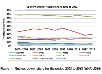
The World Nuclear Association (WNA, 2015) states that as at April 2015, there were 437 nuclear reactors in operation, with another 65 under construction and a further 481 either in planning or proposed. Clearly, there is significant potential for the application of friction processing techniques in this power sector. The age of reactors varies, from firstgeneration reactors developed in the 1950s to the current generation III reactors introduced in 1996 in Japan, with generation IV reactors still under development with a proposed introduction date of 2020. The main reactor types currently operational are pressurized water reactors (PWRs) - 273 units, boiling-water reactors eactors (CANDU-PHWR) - 48 units, gas-co(BWRs) - 81 units, pressurized heavy-water roled reactors (AGR and Magnox) - 15 units, light-water graphite reactors (RBMK and EGP) -15 units, and fast neutron breeder reactors (FBR) - 2 units (WNA, 2015).
The majority of reactors currently in operation are relatively elderly in terms of their design life and would require decommissioning in the short term if life extension methodologies are not adopted. The high capital cost and extensive lead time involved in bringing new nuclear plants online make the whole idea of accurately determining the remaining life of existing plants very topical.
The graphs in Figure 1 and Figure 2 were populated from data published by the WNA (2015) in 2015 and give an indication of the current operational plants, plants under construction, and proposed plants. Considering Figure 1, which shows the percentage contribution from nuclear fission, over the decade 2003 to 2013, to the electric power needs of both the 'BRICS' nations and of developed countries, it is clear that most of these countries made very little capital investment in additional nuclear generation capacity, with most countries showing a moderate decline in nuclear contribution. With the exception of France, and to a lesser extent Brazil, most countries currently obtain less than 10% of their electricity needs from nuclear. The future for nuclear power looks much more promising when one considers the potential additional capacity from the current build programme, and the planned and proposed additions to the nuclear fleet over the next 20 years (Figure 2).
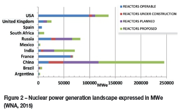
Therefore, taking an overview of the installed, planned, and proposed future nuclear capacity, and factoring in developments in respect of the safer, more standardized and cost-effective generation IV reactors, there is considerable opportunity to plan for the implementation of alternative joining and repair technologies in the nuclear industry.
The basic principles of generating electricity from nuclear fission are very similar to those used in fossil-fired thermal power plants, if viewed from the secondary circuit (steam generation) point onwards. Steam generated by controlled nuclear fission is used to drive turbines, which are interconnected with electrical generators. A number of the main materials used in the construction of nuclear power plants, including Zircaloy, can be joined or repaired by friction-based processes. The joining of thin-wall sections intended for use in fuel rod application by rotary friction processes is currently being studied at the Nelson Mandela Metropolitan University (NMMU) Work is also being done on Cr-Mo-V alloy steels and various grades of stainless steel.
Friction processing technologies
One of the simplest ways to warm up your hands is to rub them together. This action generates heat in proportion to the rapidity of the rubbing motion, the pressure applied on the rubbing surfaces, and the duration. Similar concepts are used to provide the primary thermal energy source in friction processing (FP), allowing lower temperature solid-state joints and repair processes to be applied to a wide variety of materials (particularly the magnesium and aluminium light alloys) used in manufacturing industry (Thomas and Duncan, 2010). In summary, friction processing comprises a set of solid-state joining techniques that are carried out by generating heat at a contact interface. This softens the material and allows plastic flow to occur which, in combination with an applied pressure, can be used to create strong, low-defect, and low tensile residual stress bonds (Maalekian , 2007; Gibson, 1997; ASM International, 1993; Serva-Tech Systems, n.d. (a); Thomas and Dolby, 2001).
There are various types of friction processes, as illustrated in Figure 3.
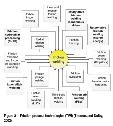
The main friction processing joining technologies considered in this paper are rotary friction welding (RFW), friction stir welding (FSW), friction hydro-pillar processing (FHPP, which can employ either tapered or parallel sided configurations), and linear friction welding (LFW). LFW is a relatively new and versatile process that permits the joining of irregular shapes, allowing for near-net-shape fabrication. In this range of friction technologies, there are autogenous processes that form a joint by using parent material only (RFW and LFW), i.e. without the addition of any filler metal, processes that make use of a consumable tool (FHPP), and processes that use non-consumable tools (FSW).
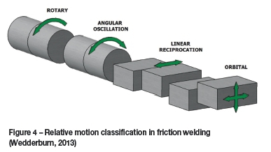
There are four basic classifications for relative motion in friction welding (BSI Group, 2000; Serva-Tech Systems, n.d. (b)), namely: rotary, angular oscillation, linear reciprocation, and orbital motion. Figure 4 illustrates these various motions.
Fabrication by frictional heating is a well-established technology. The first use of friction knowledge to process and shape materials dates back to 1891, when Bevington (1891) used heat generated by friction to form and join tubes.
Rotary friction welding (RFW)
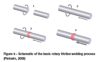
RFW is a well-established 'workhorse' friction joining technology that has been widely used for over a century in numerous applications ranging across the automotive, construction, aerospace, and medical sectors. Two alternative RFW techniques, known as continuous drive and inertia friction welding, are currently in use; the latter is the most widely adopted process. In both techniques joints are made by placing a rotating component in contact with a stationary component while applying a load perpendicularly to the contact interface. Once the interface reaches the appropriate welding temperature to plastically displace and fuse the materials by forging, rotation is stopped and the weld is allowed to solidify while maintaining the forging force (Thomas and Duncan, 2010; Thomas, Nicholas, and Kallee, 2001) as illustrated in Figure 5. The differences between the two methods are mainly in process control, with continuous drive welding being done with a constant rotational speed that may be varied at different stages of the weld cycle, while during inertia welding the process begins at a relatively high rotation speed, which gradually reduces to zero (Thomas and Duncan, 2010).
Friction hydro-pillar processing (FHPP)
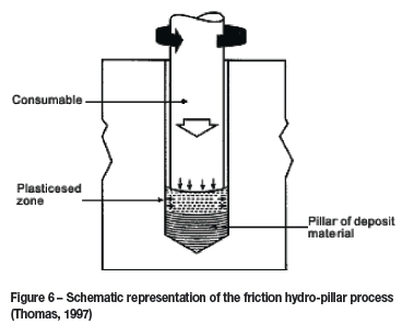
Like most of the modern friction technologies, FHPP (Figure 6) was invented and patented by TWI (World Centre for Materials Joining Technology) in the UK in the early 1990s. A description of the process, as given by Thomas and Nicholas (1992), states that friction hydro-pillar bonding is achieved by rotating a consumable tool coaxially in a hole while under load. The frictional heat generated results in the production of a pillar of continuous plasticized layers until the hole is filled. The plasticized material consists of a series of shear layers or interfaces which solidifies under the influence of the applied force. One of the main original observations was that the plasticized material advances more rapidly than the axial feed rate of the consumable tool, which results in the rising of the frictional interface along the consumable tool to form the dynamically recrystallized deposit material. During the process a good degree of plasticization must be maintained at the interface, allowing hydrostatic forces to be transmitted axially and radially to the inside of the hole in order to achieve a good metallurgical bond (Thomas and Nicholas, 1992).
A large body of reported work from various laboratories has shown that good mechanical integrity can be achieved in FHPP welds, with metallographic examination indicating a fine-grained microstructure in the welded zone (TWI Bulletin, 1997). The original geometry proposed for the FHPP process was based on a horizontal cylindrical arrangement, with specific clearance between the tool and the sides of the hole. However, in more recent applications tapered holes and consumables are becoming more common, in which the angle of the two tapers is slightly different (Thomas and Temple-Smith, 1996; Bulbring et al., 2012; Meyer, 2001). Wedderburn (2013) reported that the tapered arrangement allows for an additional reactive force to develop horizontally from the sidewall in addition to the vertical hydrodynamic force, which can be utilized for heat generation when making the joint, and that this is beneficial for materials with poor extrusion properties.
A number of research institutes have claimed that good quality FHPP welds can be made in steel and certain non-ferrous materials using a parallel hole geometry. In this context a 'good quality' weld is characterized by high impact, tensile, and bend properties (TWI Bulletin, 1997). This sentiment is supported by Wedderburn (2013) Bullbring, et al., (2012) who reported that good mechanical properties were achieved with a taper configuration on most thick-wall steam pipe materials evaluated. Where welds were made using parallel tool and holes, periodic changes in the microstructure were observed, where regions within the deposit material were not fully transformed. This effect was more noticeable when a high tool rotation speed and consumable displacement (upset) rate were used. Microstructural variations were also exacerbated when the hole depth to hole diameter exceeded a ratio of about 3.5:1 (Meyer, 2003).
There is limited published work on the influence of process parameters on FHPP welds. From the work by Meyer (2003), Wedderburn (2013), and Bulbring et al., (2012) on the use of FHPP for high-strength low-alloy steel, it is apparent that hole geometry is more critical than tool shape. Meyer (2003) also noted that the influence on heat generation and bond quality is similar to that observed in conventional friction welding, although the rotational speed required for a good FHPP weld is significantly lower than in conventional friction welding. The forging force, which has a major influence on weld properties in conventional friction welding, appears to have little or no influence on most FHPP welds and its effect is limited to the upper area near the surface region (Wedderburn, 2013; Bullbring, et al., 2012; Meyer, 2003).
Friction stir welding (FSW)
FSW must be considered as one of the leading innovations in solid-state joining in the last 50 years. Invented and patented by TWI (1991), FSW is a joining technique that allows both low and high melting point metals, including aluminium, lead, magnesium, steel, titanium, zirconium, and copper, to be continuously welded with a non-consumable tool (Nicholas, 1998; Reynolds, Seidel, and Simonsen, 1999; Dawes, 2000). The wear rate and cost of refractory tooling is a limiting factor in welding steel alloys. One of the key benefits of this solid-state friction welding technique is the capability of welding dissimilar metals as well as joining certain metals that are difficult to weld by fusion processes, e.g. 2xxx series aluminium alloys. The process can best be described as a continuous 'hot-shear' process involving a non-consumable tool that is responsible for mixing and forging the metals across the joint line (Delany et al., 2005). Selection of the tool geometry and material are important considerations in achieving a sound joint. The most important aspects of tool design are the pin and shoulder geometry, as these are responsible for forming the joint.
The basic principle of the FSW process involves plunging a rotating tool between abutting faces of the work piece and then traversing it along the joint line (Figure 7). Rotary motion of the tool generates frictional heat at the contact surfaces, softening the material and creating a plasticised zone around the tool pin and below the shoulder.
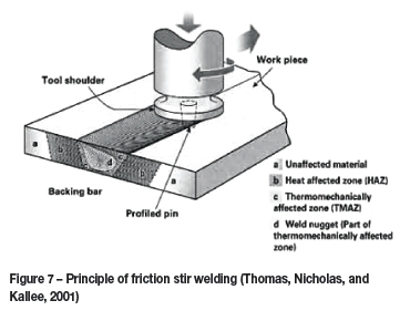
Apart from generating heat, the shoulder also contains the plasticized material in the joint zone, which provides a forging action that assists with the formation of a defect-free solid-state joint. In the nuclear industry, FSW has been applied to the manufacture of copper canisters for encapsulating nuclear waste (Andersson and Andrews, 1999) as well as for leak sealing or material reprocessing techniques used in the repair of surface-breaking or near-surface defects (Von Wielligh, 2012).
Linear friction welding (LFW)
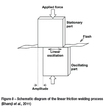
(LFW is a joining technology that is ideal for welding non-symmetrical components. This solid-state joining process generates frictional heat through the linear forced interaction between a stationary surface and a reciprocating surface (Nentwig, 1995; Nicholas, 2003). The process requires a large force applied perpendicular to the weld interface and, as there is no containment of the hot plasticized material, a continuous layer of flash is expelled during the rapid linear movement. Since this softened 'third-body' material is not contained, surface oxides and other impurities are ejected together with the plasticized 'flash' (Bhamji et al., 2011).
Unfortunately, LFW requires a major capital investment due to the complexity and size of the welding platforms. The high process force must be contained within the platform structure, while achieving the required level of displacement and process control necessary to ensure joint integrity and geometrical accuracy means that tight specifications are set on all system components and control algorithms. Hence LFW is considered feasible for the production of high-value engineering components, e.g. joining of aero-engine compressor blades to compressor disks (Wanjara and Jahazi, 2005). LFW applications are predicated on the suitability of the process for joining materials with good high-temperature properties, low thermal conductivity, and acceptable compressive yield and shear strength properties (Wanjara and Jahazi, 2005). Low thermal conductivity helps confine heat to the interface region, while appropriate high-temperature properties (high yield strength and melting point) allow a high level of frictional heat generation to occur before plastic collapse. Materials with good high-temperature mechanical properties and low thermal conductivities, e.g. titanium, zirconium, and nickel alloys, are particularly suitable for LFW applications.
Applications of friction technologies in the nuclear industry
A number of studies have shown that friction welding can be used to make sound joints and cost-effective repairs in the nuclear industry. These include the work done in a Swedish programme that evaluated FSW for encapsulating nuclear fuel waste (Andersson and Andrews, 1999), while TWI demonstrated that thermocouple probes can be fitted to boiler header domes forged from 316 austenitic stainless steel for the Hartlepool and Heysham nuclear power stations (TWI Global, 2014). Hy-Ten, an independent rebar and accessory supplier, has gained approval for supplying friction welded rebar couplers to be used in concrete construction by the nuclear industry (Maguire, 2012). Locally, the NMMU has developed two technologies with potential applications in the nuclear industry; one relating to leak sealing by FSW that employs a low-force partial-penetration methodology, and the other the registered Weldcore® process, which employs FHPP principles to core and repair sites used for creep assessment as part of remaining life evaluation.
Nuclear waste storage encapsulation using FSW
This project formed part of a Swedish programme that evaluated new ways of encapsulating nuclear fuel waste before storing it underground. The capsules were manufactured from copper and consisted of a copper cylinder with a base and lid (Andersson and Andrews, 1999). The capsule demand was estimated at 200 per year. Important considerations in fabrication included inspection of the welds and guarantees on achieving defect-free joints that would prevent water entering the canister during long-term storage underground (Swedish Nuclear Fuel and Waste Management Co. (SKB), 2001). Typical canister dimensions were diameter 1050 mm, length 4830 mm, and a total weight of 27 t. To satisfy the design requirements for environmental and chemical resistance, a copper alloy equivalent to EN 133/63 with a 50 mm wall thickness was selected for the canisters. To improve creep resistance of the copper, 50 ppm of phosphorus was specified in the alloy (Swedish Nuclear Fuel and Waste Management Co. (2001). The project developed an electron-beam welding solution for sealing the capsules and also considered the use of FSW. The main consideration in selecting FSW as a potential alternative process was the solid-state nature of the joining process, together with the ability to make high-quality welds with a fully automated platform and standardized tool technology.
The investigation of FSW as an alternative joining process started by considering the welding of 10 mm thick copper plate strips about 0.5 m in length. This study was used to find a suitable tool material as well as evaluate different tool geometries. The only reference study at the time involved FSW of thick-section aluminium plate with melting temperatures (659°C) well below that of copper (1083°C). However, copper tends to soften at lower a temperature, which allows the use of FSW on thick copper sections (Swedish Nuclear Fuel and Waste Management Co., 2001). This study led to the specification of process forces and power requirements for welding 50 mm copper plate. This was done by progressively increasing the plate thickness to 50 mm while checking that the weld microstructure remained acceptable for the identified application. The weld zone showed a fine equiaxed grain structure in the weld nugget region. Based on the success of these initial trials, SKB proceeded with the development of a FSW platform to weld lids to short (2 m) sections of 50 mm thick tubes. The tube was placed in a vertical position with the welding head and tool in a horizontal position while the welding head rotated around the tube. For each weld, specific weld parameters were recorded, providing a complete record of all the essential variables and their control during the welding process. These results, in conjunction with non-destructive testing, form an important resource for interpreting weld parameters and data.
Once adequate circumferential friction stir-welded joints were achieved, attention was focused on eliminating the exit hole left at the end of the weld run. This project has clearly demonstrated the feasibility of fabricating capsules by FSW to enclose nuclear waste for long-term storage.
Leak sealing by FSW
Nuclear facilities situated close to the ocean could experience material degradation, especially of stainless steel vessels and pipework, arising from environmentally-induced stress corrosion cracking (SCC). This prompted an investigation into identifying a suitable refurbishment technique that would provide a cost-effective and permanent leak-sealing/SCC repair technique. Implementation of the repair process was required to have no influence on the operation of the plant, and also to fulfil the stringent nuclear safety regulations. The NMMU was therefore requested to investigate the feasibility of using FSW as a potential leak-sealing technique for 304L stainless steel. This study focused on establishing a technology procedure for the identified application, which entailed reviewing the process, tool material, and tool geometry designs to develop a solution suitable for high-temperature FSW of unsupported, partial penetration leak sealing of 304L stainless steel with water backing.
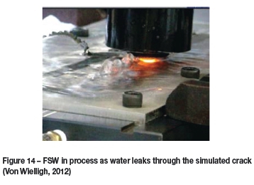
The approach taken in the investigation was initially to establish a theoretical processing parameter window from published literature. Subsequently, a suitable tool alloy and tool profile were identified before preliminary experimental work led to a low-force processing window for 304L stainless steel. Various experiments were carried out to determine the effect of process parameters on weld quality and the processing forces required to achieve high quality. The governing factor was found to be the downwards forging force required to achieve a fully consolidated, partial penetration weld that would seal a leak in stainless steel sheet resulting from, for example, SCC. Finally, a complete weld procedure specification was proposed and evaluated by welding on a mock-up of the real application with water seeping through the simulated crack during the welding process. In principle, this is a similar concept to FSW under water, which has been reported by Ambroziak and Gul (2007).
Such applications require refractory tool materials, and W-25wt%Re was selected for the leak-sealing application as it provides good resistance under conditions of uneven surfaces, high vibratory loads, and plate deflection (Von Wielligh, 2012). Additional benefits include the ability to reprofile the tool using standard machining processes, hence increasing tool life. Process development focused on establishing a low-force processing window for the 304L stainless steel that minimized plate deflection during welding in an unsupported condition. The investigation led to the development of a new dual-control tool plunge strategy, in which the operator controls the maximum downwards Z-force during the plunge stage while simultaneously controlling the plunge rate and depth (see Figure 9). Plunge rate is, however, also a function of the Z-force feedback, which could be seen as a significant advantage because the maximum plate deflection at the start of the weld can therefore be limited (Von Wielligh, 2012).

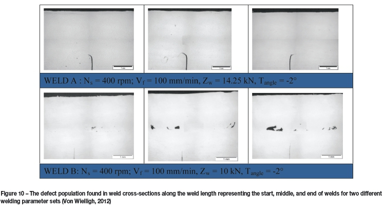
The minimum Z-force required for repeatable weld consolidation using tools with a 14 mm, 12 mm, or 10 mm diameter shoulder was found to be 14.25 kN, 10.5 kN, and and 9 kN respectively (Von Wielligh, 2012). This investigation showed that water cooling and water seepage through the simulated SCC had only a minor effect on weld quality and that the dominant factor influencing weld quality was plate deflection. A full preliminary welding procedure specification was developed for both the 14 mm and 12 mm shoulder diameter tools, but only the procedure for the 14 mm tool was deemed robust enough for industrial application.
Un-etched images of typical weld cross-sections obtained during the repair trials of SCC in stainless steel are shown in Figure 10. This figure shows the defect population observed at the start, middle, and end positions in two welds, A and B, made using different weld parameters while water was seeping through the SCC, using two different sets of process parameters.
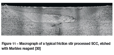
On the etched specimen in the macrograph in Figure 11, the lighter etching material clearly shows a well-defined flow pattern in the weld cross-section. This material was found to be tungsten, a by-product of tool wear that has diffused into the weld. The darker line extending beyond the flaw intended to simulate a stress corrosion crack at the bottom of weld cross-section is termed a 'lazy S' defect in FSW and is not part of the simulated crack. It is generally ascribed to the presence of oxidation and corrosion by-products of the wire cutting process, and serves as a good indication of how actual corrosion products are likely to be distributed across the weld.
Vickers microhardness tests did not show any significant change in the hardness of the weld area or heat-affected zone compared with the parent material. This is to be expected, as austenitic stainless steels are not hardenable by heat treatment (Von Wielligh, 2012).
The feasibility of applying this FSW process to crack repair in industry was tested using a mock-up of the industrial application of a tank containing a stress-corrosion crack. A simulated crack was successfully welded in an unsupported 304L stainless steel plate surface in the annealed condition with water backing up to a depth of 2 mm.
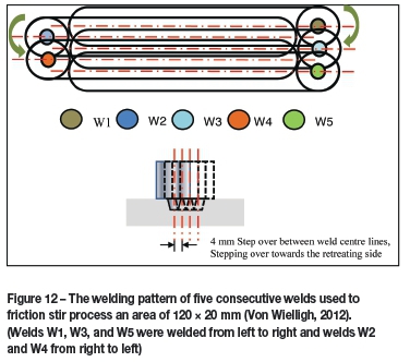
The weld repair process required making a number of overlapping friction stir welds, with a step distance between them equal to the pin diameter. The step direction was towards the retreating side of the weld, because flash formation arising from plate deflection made it impractical to step towards the advancing side.
The typical weld repair pattern is shown in Figure 13. The first weld, W1, is carried out from left to right with a clockwise spindle rotation. The retreating side of the weld is thus located at the bottom. The second weld, W2, is carried out from right to left with an anticlockwise spindle rotation such that the retreating side remains at the bottom of the weld. This process of alternating welds is continued until the cracked area has been covered.
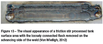
Figure 13 shows an example of such a weld repair with five overlapping welds, covering an area of 120 mm χ 20 mm. In this figure, all the loosely attached flash has been removed.
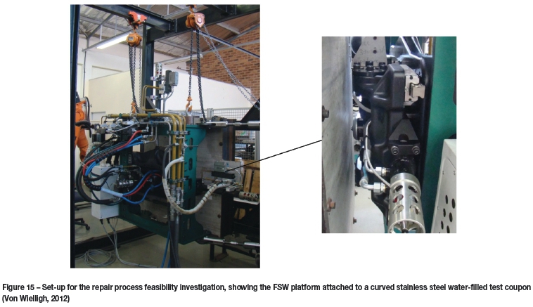
This investigation has shown that leak sealing of stress-corrosion cracks in an unsupported tank surface is possible by using overlapping, partial penetration, friction stir welding. The investigation also highlighted the fact that due to material thinning during the FSW process, the total area than can be repaired has to be limited, based on allowable plate thinning. A reduction in the original plate thickness occurs with each successive overlapping weld. The decrease in plate thickness is likely to be a function of plate thickness; in other words, dependent on constraint. Furthermore, FSW tool exit holes can be partially eliminated by using tools with a retractable pin. In summary, FSW is a potential repair technique for SCC, although for unsupported welding careful consideration must be given to the influence of plate thickness, surface condition of the area to be processed and its size, and deflection during welding, as well as the permanent deformation (thinning) induced by the process. FSW is also likely to alter the metallurgical and mechanical properties in the processed area, and this aspect also needs consideration. Associated friction processes such as friction surface dressing or friction cladding could also be considered for such repair procedures if it is accepted that the main purpose of the process is not to recover structural integrity, but rather top-seal seepage of the liquid inside the tank through stress corrosion cracks. Friction cladding is an additive process, which has the potential to reduce plate deflection and permanent deformation imposed by the friction process. Figure 14 shows the heat generation in the tool while traversing along a repair zone with water leaking through the simulated crack. The installation of the developed platform is shown in Figure 15.
Weldcore® sample removal and repair technology
Ongoing assessment of the remaining life of high-temperature and -pressure (HTP) components in nuclear power stations is of paramount importance in ensuring their safe and cost-effective operation. Although failure can have severe consequences, economic considerations are requiring operators to extend the operating lives of plants currently in operation. To ensure safe operation, more direct experimental assessments have to be made of remaining life to complement and underpin prediction models. Neutron irradiation embrittlement is one of the concerns for the nuclear industry, as this could limit the service life of reactor pressure vessels. Improved understanding of the underlying causes of embrittlement and better calibration of prediction models will provide both regulators and power plant operators with improved estimates of vessel remaining life (Odette and Lucas, 2001). The NMMU, in collaboration with Eskom, has developed the patented Weldcore® process, which is a sampling and repair process that is currently used in fossil fuel power stations to assist in sample removal for creep damage assessment.
The process involves removal of a cylindrical metallurgical sample and hole preparation for repair in four steps, as illustrated in Figure 16. The hole is then repaired using friction taper hydro-pillar processing (FTHPP) as illustrated in Figure 17.

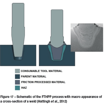
Current Weldcore® applications are primarily in a coring and repair procedure for local metallurgical sample removal sites. The advantages of the process are that the metallurgical core can extend much closer to the centre of a thick-walled pressure pipe, and that the coring and repair can be accomplished during plant operation. The core hole may be either tapered or vertical-sided, depending upon the thickness of the material to be welded and the depth of the hole. For deeper repair welds, a cylindrical configuration for the hole and rotating tool is recommended to ensure that the process force and torque are limited. The consumable rotating tool is typically made of the same alloy as the base metal, although it is possible to achieve a matched, over-matched, or under-matched weld zone. On completion of the weld, the remaining portion of the consumable rotating tool can be cut off and ground flush with the metal surface. Since the 'weld' does not produce a liquid weld puddle, the orientation of the weld is not affected by gravity, hence making the process position-independent.
The main factors making the Weldcore® process attractive to the nuclear fraternity relate to platform size (which is compact and hence suitablefor on-site work) and a high degree of process automation. The Weldcore® platforms were initially developed for high-temperature steam pipes used in power stations. However, the success of the platform has led to further developments for applications that include turbine disc and reducer sections.
Figure 18 shows the modular arrangement and adaptability of the welding platforms that were developed at the NMMU for specific applications of the Weldcore® process in the power generation industry.

The in-situ application on steam pipes required the design and development of a portable reconfigurable platform that allowed operation at various locations throughout a power station. The modular arrangement of the welding platform, involving a frame, spindle, and drive motor, facilitates ease of transport, positioning, and mounting. Electrical and hydraulic power and control connections are operated via a remote control unit.
The process and portable platform allow for the in-situ removal of a representative sample of metal from a structure (pipes, turbine rotors, etc.) that can be used for accurate metallurgical assessment of the remaining life of the structure. It provides superior data to other current methods as the excised core is a far more representative sample of the through-thickness than other techniques, with a shorter acquisition downtime. The process has been tested on steam pipes and turbine components in the power generation industry and is in the final phases of being tested on structures on a petrochemical plant. The main benefit of the Weldcore® process is a reduction in the risk of failure and hence better management of safe life in high-value engineering components.
Discussion
The introduction of a new or alternative joining and repair processes into the nuclear industry entails a number of challenges from the engineering and regulatory points of view. Nuclear power, for obvious reasons, is a tightly regulated industry, but the authors propose that by introducing improved life assessment standardization, the risk and complexity of safely operating these types of facilities could be further reduced. Cost-effective condition monitoring is an implicit part of life extension for ageing plant, and of the through-life cost and performance optimization of new installations.
Friction processing presents a viable alternative methodology for some aspects of condition monitoring and repair of thermal power plant, with significant advantages accruing from its solid-state nature (which opens the door to welding of dissimilar metals). A solid-state joining process limits microstructural phase transformations, while lower process temperatures result in a significant reduction in thermal stresses and associated distortion compared with conventional fusion welding processes. The lower thermal gradient results in a narrow heat-affected zone with a fine equiaxed weld nugget and limited grain growth in the thermomechanically transformed region. These microstructures are normally associated with good strength and toughness. As illustrated in the applications presented in this paper, friction processing lends itself to a high degree of automation and process control, giving repeatable welds and allowing sophisticated monitoring of weld quality. Friction welding offers the power generation industry a clean, reconfigurable welding process suitable for complex and bespoke applications and which can greatly reduce process time and cost of condition monitoring and repair.
References
Ambroziak, A. and Gul, B. 2007. Investigations of underwater FHPP for welding steel overlap joints. Archives of Civil and Mechanical Engineering, vol. 7, no. 2. pp. 67-76. [ Links ]
Andersson, C-G. and Andrews, R.E. Fabrication of containment canisters for nuclear waste by friction stir welding. Proceedings of the 1st International. Symposium on Friction Stir Welding, Rockwell Science Center, Thousand Oaks, California, 14-16 June 1999. [ Links ]
ASM International. 1983. Metals Handbook. Volume 6 - Welding Brazing, and Soldering. 9th edn. Materials Park, Ohio. [ Links ]
Bevington, J. (1891. Spinning tubes mode of welding the ends of wire, rods, etc, and mode of making tubes. US patent 463134, 1891. [ Links ]
Bhamji, I. Preuss, M., Threadgill, P.L., and Addison, A.C. 2011. Solid state joining of metals by linear friction welding: a literature review. Materials Science and Technology, vol. 27, no.1. pp. 2-12. [ Links ]
Boldyrev, R.N. and Voinov, V.P. 1980. Possible reasons for the formation of extremum of torque during heating in friction welding. Welding Production, no. 1. pp. 10-12. [ Links ]
BSI Group. (2000. Welding - friction welding of metallic materials. British Standard BS EN ISO 15620-2000. London, UK. [ Links ]
Bulbring, D.L.H., Hattingh, D.G., Botes, A, and Odendaal, D.H. 2012. Friction hydro pillar process as an alternative repair steel structures. FERROUS 2012. Ferrous and Base Metals Development Network Conference, Magaliesburg, South Africa, 15-17 October 2012. Southern African Institute of Mining and Metallurgy, Johannesburg. [ Links ]
Dawes, C.J. 2000. Faster and faster - welding speed increases with tool development - one of a series of steps. Bulletin, vol. 41, no. 4. pp. 51-55. [ Links ]
Delany, F., Lucas, W., Thomas, W., Howse, D., Abson, D., Mulligan, S., and Bird, C. 2005. International Forum on Welding Technologies in Energy Engineering. Shanghai, China, 21-23 September 2005. [ Links ]
Gibson, S.W. 1997. Advanced Welding. Chapter 12 - Friction Welding. McMillan, London. [ Links ]
Godet, M. 1984. The third-body approach: a mechanical view of wear. Wear, vol. 100. pp. 437-452. [ Links ]
Hattingh, D.G., Doubell, P., Scheepers, R., Newby, M., Von Wielligh, L., Odendaal, D., and Weddeburn, I.N. 2012. Novel core sampling technique for HP turbine rotor remaining life study. 10th Electric Power Research Institute Conference, Florida, USA. [ Links ]'
Maguire, A. 2012. Hy-Ten celebrates nuclear approvals for friction welded couplers in concrete construction. http://www.sourcewfire.com/news/73407/hy-ten-celebrates-nuclear-approvals-for-friction-welded-couplers-in-concrete# [ Links ]
Meyer, A. 2003. Friction hydro pillar processing - bonding mechanisms and properties. Dissertation, Von der Gemeinsamen Fakultät für Maschinenbau und Elektrotechnik der Technischen Universität Carolo-Wilhelmina zu Braunschweig als. Dissertation angenommene Arbeit. GKSS- Forschungszentrum Geesthacht GmbH. [ Links ]
Maalekian, M. 2007. Friction welding - critical assessment of literature. Journal of Science and Technology of Welding and Joining, vol. 12, no. 8. pp. 708-729. [ Links ]
Nentwig, A.W.E. 1995. Untersuchungen zum linear-reibsscheissen von metallen. Schweissen und Schneiden, vol 47, no. 8. pp. 648-653. [ Links ]
Nicholas, E.D. 1998. Developments in the friction stir welding of metals. 6th International Conference on Aluminium Alloys, ICAA-6, Toyohashi, Japan. Sato, T., Kumai, S., Kobayashi, T., and Murakami, Y. (eds). Japan Institute of Light Metals, Tokyo. [ Links ]
Nicholas, E.D. 2003. Friction processing technologies. Welding in the World, vol. 47, November. pp. 11-12. [ Links ]
Odette, G.R. and Lucas, G.E. 2001. Embrittlement of nuclear reactor pressure vessels. Journal of Materials (JOM), vol. 53, no. 7. pp. 18-22. [ Links ]
Pinheiro, G.A. 2008. Local reinforcement of magnesium components by friction processing: determination of bonding mechanisms and assessment of joint properties. Dissertation, Vom Promotionausschuss der Technischen Universität Hamburg-Harburals. [ Links ]
Reynolds, A.P., Seidel, T.U., and Simonsen, M. 1999. Visualization of material flow in an autogenous friction stir weld. Proceedings of the 1st International Symposium on Friction Stir Welding, Rockwell Science Center, Thousand oaks, California, 14-16 June 1999. [ Links ]
Serva-Tech Systems. Not dated (a). Friction Welding Process Basics - report 1. http://www.frictionwelding.com/report1.htm [ Links ]
Serva-Tech Systems. Not dated (b). Direct vs Inertia Friction Welding - report 4. Not dated. http://www.frictionwelding.com/report4.htm [ Links ]
Singer, I.L. 1998. How third-body process affects friction and wear. MRS Bulletin, June. pp. 37-40. [ Links ]
Suery, M., Blandin, J.J., and Dendievel, R. 1994. Rheological behaviour of two phase superplastic materials. Materials Science Forum, vol. 170/172. pp. 167-176. [ Links ]
Swedish Nuclear Fuel and Waste Management Co. 2001. Development of fabrication technology for copper canisters with cast inserts. Technical Report TR-02-07. Stockholm, Sweden. [ Links ]
Thomas, W. and Duncan, A. 2010. Friction based technology for joining and material processing - an introduction. International Conference on Welding and Joining of Materials (ICWJM), Pontificia Universidad Católica del Peru, Lima, Peru, 9-11 August 2010. [ Links ]
Thomas, W.M. 1997. Gas additions boost friction performances. TWI Connect Press. The Welding Institute, Cambridge, UK. www.twi.co.uk. [ Links ]
Thomas, W.M. and Dolby, E. 2002. Friction stir welding developments. 6th International Conference on Trends in Welding Research, Pine Mountain, Georgia. USA, 15-19 April 2002. [ Links ]
Thomas, W.M. and Nicholas E.D. 1992. Friction hydro pillar processing TWI. Leading Edge. TWI Connect Press. www.twi.co.uk [ Links ]
Thomas, W.M. and Temple-Smith, P. 1996. Friction plug extrusion. UK Patent Application, GB 2306365. The Welding Institute, Cambridge, UK. [ Links ]
Thomas, W.M., Nicholas, E.D., and Kallee, S.W. 2001. Friction based technologies for joining and processing. TMS Friction Stir Welding and Processing Conference, Indianapolis, Indiana, USA, November 2001. [ Links ]
TWI Bulletin. 1997. The need for gas shielding - positive advantages for two friction processes. The Welding Institute, Cambridge, UK. pp. 84-88. [ Links ]
TWI Global. 2014. Friction welding proves perfect in nuclear work. http://www.twi-global.com/news-events/case-studies/friction-welding-proves-perfect-in-nuclear-work-097/. [ Links ]
Von Wielligh, L.G. 2012. Un-supported friction stir processing of stress corrosion cracks in a 304L stainless steel tank surface. Technical Report TS008-A. eNtsa, Nelson Mandela Metropolitan University. [ Links ]
Wanjara, P. and Jahazi, M. 2005. Linear friction welding of Ti-6Al-4V: processing, microstructure, and mechanical-property inter-relationships. Metallurgical and Materials Transctions A, vol. 36A, no. 8. pp. 2149-2164. [ Links ]
Wedderburn, I.N. 2013. Development of a creep sample retrieval technique and friction weld site repair procedure. PhD thesis, Nelson Mandela Metropolitan University, Port Elizabeth, South Africa. [ Links ]
World Nuclear Association (WNA). 2015. http://www.world-nuclear.org/info/Facts-and-Figures [Accessed 2 May 2015]. [ Links ]
Paper received Aug. 2015.

