


Services on Demand
Article
 English (pdf)
 Article in xml format
 Article references
Indicators

Related links
-
 Cited by Google
 -
 Similars in Google
Share

 Permalink
Journal of the Southern African Institute of Mining and Metallurgy
On-line version ISSN 2411-9717
Print version ISSN 2225-6253
J. S. Afr. Inst. Min. Metall. vol.115 n.7 Johannesburg Jul. 2015
http://dx.doi.org/10.17159/2411-9717/2015/V115N7A8
GENERAL PAPERS AND TECHNICAL NOTE
Investigation of stress in an earthmover bucket using finite element analysis: A generic model for draglines
O. Gölbaşi; N. Demirel
Department of Mining Engineering, Middle East Technical University, Ankara, Turkey
SYNOPSIS
Draglines are massive machines extensively utilized in opencast mines for overburden stripping. The demanding working environment induces fractures, wear and tear, and fatigue failures in dragline components and eventuates in extended maintenance, lengthy downtimes, and loss of production. The bucket is the main source of external loads on the machinery, since interactions with ground materials take place in this region. This study aims to develop a generic finite element model of the stress on an operating bucket. This entails (i) three-dimensional modelling of a dragline bucket, (ii) analytical estimation of resistive forces in the bucket movement, (iii) three-dimensional simulation of the moving bucket using finite element analysis (FEA), and (iv) sensitivity analysis to examine the effect of formation characteristics on stress variation. Simulation results imply that the drag hitch and digging teeth are the elements of the bucket that are most prone to failure. In addition, sensitivity analysis indicates that internal friction angle of the formation is the dominant parameter leading fluctuations in stress values. Changes in stress level are least influenced by formation density.
Keywords: dragline bucket, formation-bucket interaction, stress distribution, finite element analysis, sensitivity analysis
Introduction
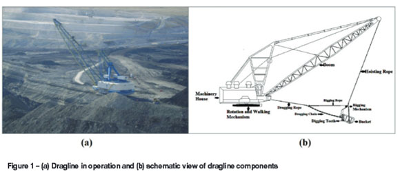
Draglines are self-operated stripping machines employed for removing of overburden material in opencast mines without assistance from a haulage machine (Figure 1). These earthmovers can be more than 4000 t overall weight, with bucket capacities commonly 90-120 m3, and have a capital cost up to US$100 million (Townson, Murthy, and Gurgenci, 2003). The productivity of a dragline is influenced by various considerations arising from operational, environmental, and human-based issues. Irregularities and inhomo-geneities in the environment of operation and the resultant stress variations are the main issues that cause unsteady loading of the front-end components of a dragline. Stress accumulation and induced damage to mechanical elements results in downtime, delays in the production schedule, and increased maintenance costs and contractor expenses. During stripping, the resistance encountered by the bucket is absorbed and transmitted to other components of the dragline such as the drag chain, hoist chain, rigging, and boom. The bucket is the source of external forces during operation. Therefore, investigation of the locations of stress concentration on the bucket is of paramount concern for better clarification of potential deficiencies in the bucket. Finite element analysis (FEA) can be effectively utilized to simulate actual cases of the dragline earthmoving process.
FEA has been extensively utilized in many studies to develop models of the interaction between formation and digging tool. Mouazen and Nemenyi (1999) developed a FEA model to simulate the formation cutting process in sub-layers with various geometries. Fielke (1999) presented a model revealing the effect of cutting edge geometry on the required cutting force. Davoudi et al. (2008) generated a model capable of estimating draft forces during tillage operation. Frimpong and Demirel (2009) examined the stress distribution along a dragline boom using FEA together with results acquired by kinematic and dynamic modelling of the boom. Brittle and plastic deformability of the formation subjected to the earthmoving process have also been investigated (Chi and Kushwaha, 1989; Raper and Erbach, 1990; Aluko and Chandler, 2004; Aluko, 2008).
The current study intends to bring innovation to dragline productivity by examining stress distributions on the bucket body.
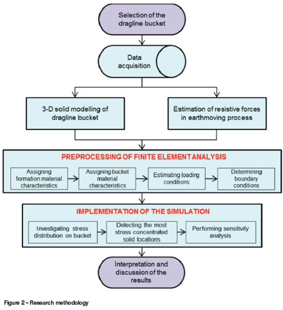
The development of a 3D solid modeling of a dragline bucket is described. This is followed by an estimation of the resistive force exerted by the formation encountered in earthmoving activity. The procedures and assumptions regarding FEA within the scope of study are discussed, an investigation of the released stress distribution and sensitivity analysis is presented, and conclusions are drawn from the study. The framework of the research methodology followed is illustrated in Figure 2.
Solid modelling of dragline bucket
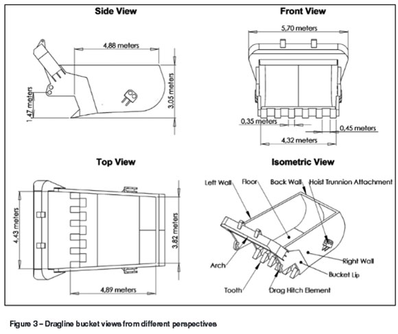
A dragline bucket body is composed of a back wall, two sidewalls, a floor, an arch, a bucket lip, and teeth that create space to gather unconsolidated or soft material during excavation. The sidewalls of the bucket are slightly inclined outward. Borders outlined by sidewalls provide rearward space with an upward tapering. The back wall has a convex configuration with oblique extension. The anterior sections of the sidewalls and the floor are integrated with bucket lip at the front. A rope and chain assembly moves the bucket vertically, and digging teeth are attached to the bucket lip using connection links. An example of a dragline bucket with 50 m3 capacity modelled in Solidworks (Dassault Systèmes SolidWorks Corporation, 2009) can be seen in Figure 3. The bucket model has a mouth opening of 4.32 m and six digging teeth 0.35 m in width. The bucket body extends 4.88 m in length, 3.05 m in height; and the width tapers from front to back.
Prediction of formation resistive force
An earthmoving process is a succession of consecutive formation failures due to the interaction between the formation and excavation tool. Estimation of resistive forces resulting from action-reaction behaviour of the formation is essential to calculate the opposing stresses during the stripping movement of a dragline bucket. There are various empirical and analytical methods available for analysing the forces that are generated during formation cutting. Some researchers have observed the performance of various earthmoving machines to predict the cutting resistance of the formation empirically (Alekseeva et al., 1995; Zelenin, Balovnev, and Kerov, 1986; Nedoredzov, 1992, Hemami, Goulet, and Aubertin, 1994). In addition, there are many other studies that have investigated the formation-tool interaction in 3D or 2D perspective using analytical methods. Since empirical definitions are constructed from specific field observations, these methods are not able to offer representative estimations for other sites. Analytical methods, however, can be more objective in defining earthmoving processes by a holistic approach. This research study utilizes an analytical approach to calculate the approximate resistive forces imposed on a dragline bucket in operation.
Analytical techniques can be handled as 2D or 3D according to the area of utilization. As cited in Blouin's review study (Blouin, Hemami, and Lipsett, 2001), 3D models (McKyes, 1985; Swick and Perumpral, 1988; Boccafogli et al., 1992) incorporate the effect of accumulated material at the edges of the digging tool during operation. 2D approaches, on the other hand, do not consider the side effect of the formation resistance in modelling (Osman, 1964; Gill and Vanden Berg, 1968; McKyes, 1985; Swick and Perumpral, 1988). The shape of the excavation tool can be used in decision-making to designate the dimensional type of process. Excavation tool shapes are generally classified as bucket and blade types. 2D resistance models are convenient for bucket movement since the sidewalls of the body ensure the direct passage of cut material to the inside and, unlike scraper blades, accumulation of material is restricted, (Blouin, Hemami, and Lipsett, 2001; McKyes, 1985). This paper utilizes McKyes's 2D model (McKyes, 1985) as given in Equation [1] to estimate the forces due to weight, cohesion, adhesion, overloading, and inertia to express the resistance of a formation to earthmoving.

where
T is the resultant cutting force
w is the cutting width
γ is the density of the formation
g is the gravitational acceleration
d is the tool depth
c is the cohesion
Ca is the adhesion
q is the overload
v is the formation cutting velocity
Νγ is the weight coefficient
Ncis the cohesion coefficient
Nca is the adhesion coefficien
Nq is the overload coefficient
Nais the inertia coefficient.
McKyes's model covers many parameters that can contribute to variations in formation resistance. This research study neglects the overload pressure due to additional load on the formation surface and leading to increased compaction of the formation. Adhesion force is considered to be negligible in overburden stripping since this kind of force is encountered only in presence of frictional interaction between two heterogeneous materials. The metal composition and smooth surface of digging teeth minimizes such interaction. In addition, the inertial effect of the formation is not included in the formula since inertial fluctuations come into play only while the formation particles are being accelerated from rest to a certain velocity (Abo-Elnor, Hamilton, and Boyle, 2003). However, this study handles the model in terms of cutting the formation with constant velocity by means of a dragging action. Eventually, the general form of McKyes's equation is reduced to Equation [2].

The formula parameters obtain their values from both the cutting geometry and the deforming medium. Geometrical values can be acquired from Figure 4, which illustrates the interaction between the solid model and the medium. The total width of cutting medium (w) is 4295 mm and depth of the interaction (d) is 512 mm.
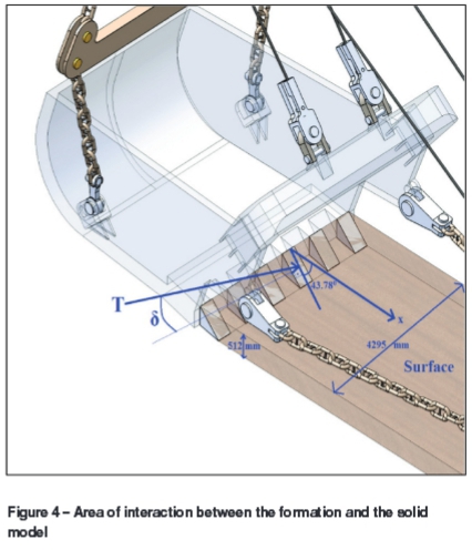
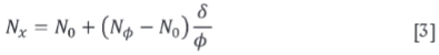
N coefficients for weight (γ) and cohesion (c) are acquired using Equation [3] and friction angle charts by Hettiaratch and Reece (1974), where δ and φ denote external and internal friction angles, respectively.
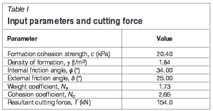
Medium parameters required for Equation [2] and Equation [3] are obtained from a tillage research study by Mouazen and Nemenyi (1999). The calculated weight and cohesion coefficient and resultant cutting force are presented in Table I. Effective resistance of the medium against the cutting force is estimated to be about 154 kN.
Finite element mesh and boundary conditions
Finite element analysis (FEA) constitutes a virtual environment to measure the reaction of a solid model under external and internal loads using nodal displacement of solid elements. Prior to implementing the analysis, pre-processing items such as material and element type, loading, and boundary conditions should be satisfied to ensure the authenticity of the model under the prescribed limits. FEA modelling and all simulation in this research study are executed in Abaqus 6.9-2 (Dassault Systèmes Simulia Corporation, 2010).
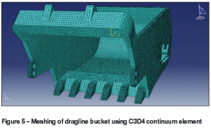
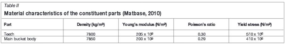
Materials are assigned to solid models using characteristics of two metals as given in Table II. The material specifications are for two casting metals with strengths of 510 and 410 MPa, exhibiting elastic-perfectly plastic behaviour. Meshing of the solid bodies is carried out using a four-node linear tetrahedron continuum element denoted as C3D4. Figure 5 illustrates the resultant meshing body, which incorporates 199 062 solid elements and 45 318 connection nodes.
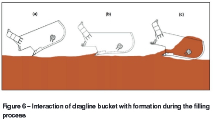
One important issue in FEA pre-processing is the designation of loading and boundary conditions in a simulation ensuring the cutting movement of dragline bucket. Dragline buckets are filled by a pull-back motion of the bucket toward the machinery housing over a distance from two to three times the bucket length (Demirel, 2011). The bucket initially penetrates the formation with the digging teeth using its own weight (Figure 6a) and then proceeds to cut the formation by means of the dragging force transmitted along the drag rope during whole filling cycle (Figure 6b and Figure 6c). The cutting action of the bucket dominates the filling cycle and leads to stripping of the formation at a velocity between 0.5-0.7 m/s (Frimpong and Demirel, 2009). Simulation in this investigation uses two external loads: the dragging force applied at the drag hitch element of bucket (Figure 3) and the formation resistance applied on the digging teeth as a distributed load.
Results and discussion
Stress distribution on the bucket
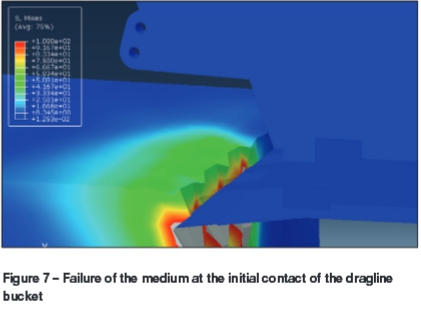
The developed model simulates the formation cutting action of the dragline bucket. Stress accumulates between the surfaces of the bucket and the formation, and the resultant failure of the formation initiates the earthmoving process. Exposure of the bucket to continuous resistance by the medium can also lead to surface fractures on the bucket body. A non-homogeneous medium and irregularities in the area being excavated may initiate stress growth and cause mechanical failure. Detection of the zones that are most prone to failure in these conditions is essential for planning preventive maintenance. The Von Mises stress distribution in the formation at 200 mm bucket movement is illustrated in Figure 7. It was observed that the Von Mises stress on the medium can reach up to 100 MPa.
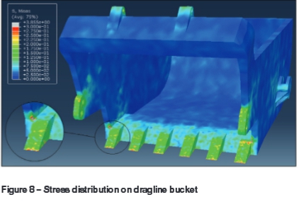
The output of finite element analysis of stress distribution on the bucket is presented in Figure 8. Von Mises stress is mostly accumulated on the front-end elements of the bucket such as the digging teeth and drag hitch element. The maximum stress on the bucket is 3.85 MPa, and the general stress is between 0.013 and 0.3 MPa. Thematic results indicate that the concerning medium sample cannot afford to fail bucket elements. However, any stress fluctuations or overloading initially induce fractures or fatigue on the red-yellow zone of the solid model as shown in Figure 8.
Sensitivity analysis results
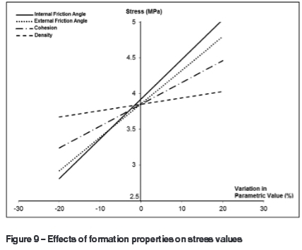
The sensitivity of stress value to variations in formation properties such as density, cohesion, internal friction angle, and external friction angle was examined to determine the formation properties that have the most influence on the stress distribution along the bucket. The effect of each parameter was measured by changing the value by ±20 per cent and determining the resultant changes in resistance forces exerted by the medium. Best-fit lines of the simulation outcomes for the modified loading conditions for a representative solid element, coded as 24753, in the tooth body are illustrated in Figure 9. The graphs indicate that fluctuations in internal friction angle have the greatest effect on the range of stress concentration on the element. Density, on the other hand, has a minimal effect on the stress value variance for the solid element.
Conclusions
Severe operation conditions on draglines, coupled with pressure for continual production and a high utilization, lead to frequent breakdowns of dragline components and ensuing pauses in production. These capital-intensive earthmovers should be operated with high reliability and availability, as well as longevity, to sustain effective production scheduling. Deterioration of the mechanical elements of draglines can be reduced by minimizing the factors that have an adverse impact on the condition of the machinery. The bucket is the source of external loads on the dragline, which are transmitted along the chain and rope assemblies. The resistive force that is generated during the dragging action of the bucket in the formation can increase the stress intensity in various parts of the bucket. Detection of areas of stress concentration in the bucket is vital to identify possible overloading states in bucket-filling operation. This study integrates solid modelling, FEA, and the analytical resistance approach to build up a generic model for the investigation of stress distribution during the dragging movement of a dragline bucket.
The simulation results indicated that the tips of the digging teeth and drag hitch elements are the most stress-intensive points and therefore most prone to failure. The highest stress value obtained on the bucket was 3.85 MPa at the prevailing boundary conditions in the simulation. Although this stress value is not sufficient to cause failure of the entire bucket body, any overloading situation may induce fractures or fatigue. Sensitivity analysis revealed that internal friction of the medium has the greatest effect on stress distribution in the bucket, whereas the density of the medium has the least influence.
References
Abo-Elnor, M., Hamilton, R., and Boyle, J.T. 2003. 3D dynamic analysis of formation-tool interaction using the finite element method. Journal of Terramechanics, vol. 40. pp. 51-62. [ Links ]
Alekseeva, T.V., Artem'ev, K.A., Bromberg, A.A., Voitsekhovskii, R.I., and Ul'yanov, N.A. 1985. Machines for Earthmoving Work: Theory and Calculations. Balkema, Rotterdam. [ Links ]
Aluko, O.B. and Chandler, H.W. 2004. A fracture strength parameter for brittle agricultural formations. Biosystems Engineering, vol. 88, no. 3. pp. 369-381. [ Links ]
Aluko, O.B. 2008. Finite element aided brittle fracture force estimation during two-dimensional formation cutting. International Agrophysics, vol. 22. pp. 5-15. [ Links ]
Blouin, S., Hemami, A., and Lipsett, M. 2001. Review of resistive force models for earthmoving processes. Journal of Aerospace Engineering, vol. 14, no. 3. pp. 102-111. [ Links ]
Boccafogli, A., Busatti, G., Gherardi, F., Malaguti, F., and Paoluzzi, R. 1992. Experimental evaluation of cutting dynamic models in soil bin facility. Journal of Terramechanics, vol. 29, no. 1. pp. 95-105. [ Links ]
Chi, L. and Kushwaha, R. L. 1989. Finite element analysis of forces on a plane formation blade. Canadian Agricultural Engineering, vol. 31, no. 2. pp. 135-140. [ Links ]
Dassault Systèmes Simulia Corporation. 2010. Abaqus 6.9-2. Rhode Island, USA. [ Links ]
Demirel, N. 2011. Effects of the rock mass parameters on the dragline excavation performance. Journal of Mining Science, vol. 47. pp. 442-450. [ Links ]
Davoudi, S., Alimardani, R., Keyhani, A., and Atarnejad, R. 2008. A two dimensional finite element analysis of a plane tillage tool in formation using a non-linear elasto-plastic model. American-Eurasian Journal of Agricultural and Environmental Science, vol. 3, no. 3. pp. 498-505. [ Links ]
Fielke, J.M. 1999. Finite element modelling of the interaction of the cutting edge of tillage implements with formation. Journal of Agricultural Engineering Research, vol. 74. pp. 91-101. [ Links ]
Frimpong, S. and Demirel, N. 2009. Case study: planar kinematics of dragline for efficient machine control. Journal of Aerospace Engineering, vol. 22, no. 2. pp. 112-122. [ Links ]
Gill, W.R. and van den Berg, G.E. 1968. Formation Dynamics in Tillage and Traction. Agricultural Research Service, Washington, USA. [ Links ]
Hemami, A., Goulet, S., and Aubertin, M. 1994. Resistance of particulate media to excavation: application to bucket loading. International Journal of Surface Mining, Reclamation and Environment, vol. 8. pp. 125-129. [ Links ]
Hettiaratchi, D. and Reece, A. 1974. The calculation of passive formation resistance. Geotechnique, vol. 24, no. 3. pp. 289-310. [ Links ]
Matbase. 2010. Material Property Database. http://www.matbase.com/material/ferrous-metals/cast-steel/ [Accessed 20 June 2010]. [ Links ]
McKyes, E. 1985. Formation Cutting and Tillage. McGill Bioresource Engineering. http://wiww.mcgill.ca/files/bioeng/BREE512_part1.pdf [ Links ]
Mouazen, A.M. and Nemenyi, M. 1999. Finite element analysis of subsoiler cutting in non-homogeneous sandy loam soil. Formation and Tillage Research, vol. 51. pp. 1-15. [ Links ]
Nedoredzov, I. 1992. Forces prediction of underwater formation cutting by excavating robots. 9th International Symposium on Automation and Construction, Tokyo. [ Links ]
Osman, M.S. 1964. The mechanics of formation cutting blades. Journal of Agricultural Engineering Research, vol. 9, no. 4. pp. 313-328. [ Links ]
Raper, R.L. and Erbach, D.C. 1990). Prediction of formation stresses using the finite element method. Transactions of the ASAE, vol. 33, no. 3. pp. 725-730. [ Links ]
Dassault Systèmes SolidWorks Corporation. 2009. Solidworks. © Concord, Massachusetts, USA. [ Links ]
Swick, W.C. and Perumpral, J.V. 1988. A model for predicting formation-tool interaction. Journal of Terramechanics, vol. 25, no. 1. pp. 43-56. [ Links ]
Townson, P.G., Murthy, D.N., and Gurgenci, H. 2003. Optimization of dragline load. Case Studies in Reliability and Maintenance. Blischke, E.W. and Murthy, D.N. (eds). Wiley. pp. 517-544. [ Links ]
Zelenin, AN., Balovnev, V.I., and Kerov, L.P. 1986. Machines for Moving the Earth. Balkema. Rotterdam. [ Links ]
Received July 2013
Revised paper received Mar. 2015

