


Services on Demand
Article
 English (pdf)
 Article in xml format
 Article references
Indicators

Related links
-
 Cited by Google
 -
 Similars in Google
Share

 Permalink
Journal of the Southern African Institute of Mining and Metallurgy
On-line version ISSN 2411-9717
Print version ISSN 2225-6253
J. S. Afr. Inst. Min. Metall. vol.115 n.5 Johannesburg May. 2015
GENERAL PAPERS
Numerical simulation of multiphase flow in a Vanyukov furnace
H.L. ZhangI; C.Q. ZhouII; W.U BingII; Y.M. ChenI
ISchool of Metallurgical Science and Engineering, Central South University, China
IICenter for Innovation through Visualization and Simulation (CIVS), Purdue University Calumet, USA
SYNOPSIS
Multiphase flow in the widely used Vanyukov furnace was numerically studied. An unsteady three-dimensional and three-phase flow model was firstly built using the computational fluid dynamics (CFD) software ANSYS FLUENT®, and then solved with the volume of fluid (VOF) and k - ε model. The results showed that the proposed model could be used to predict the multiphase movement, the slag/air fluctuation, the vortex formation, and effects of structural and operational parameters. By fast Fourier transform (FFT), the dominant frequency of density with time signal was calculated as 0.29 Hz. The analysis of different injection flow rates of enriched air indicated that this variable has a major effect on the mean slag velocity. The peak mean velocity increased from 2.17 to 4.99 m/s while the flow rate of enriched air varied from 70 to 160 m/s. The proposed model provides a method to optimize the furnace structure and operating conditions for the best furnace performance and lowest energy consumption.
Keywords: Vanyukov furnace, multiphase flow, numerical simulation, fast Fourier transform, structure optimization, operation condition optimization
Introduction
The main technologies adopted in the copper and lead reduction industries include the Vanyukov, QSL, SKS, Kivcet, Ausmelt, and ISA furnaces (Hongiu, 2001; Kojo, Jokilaakso, and Hanniala, 2000). From a fundamental theoretical viewpoint, all of these technologies can be classified as reduction bath smelting furnaces, which are the major research focus in nonferrous metallurgy. However, some of the important physical phenomena and chemical processes inside the furnace remain unknown because of the harsh reaction environments. Fortunately, numerical simulation methods, particularly computational fluid dynamics (CFD), provide an efficient way to study their internal processes.
With the development of computer software, many good CFD platforms have been released, such as Fluent and CFX. CFD has become an indispensable tool for the design and optimization of complex chemical reactors. Typical applications included the blast furnace (BF) and aluminum reduction cell. In the copper industry, some papers have been published on numerical studies of the flow pattern. The representative work in this area was carried out by Valencia and co-workers at the Institute for Innovation in Mining and Metallurgy, University of Chile ((Vaencia et al., 2004, 2006; Fuentes etal., 2002). They conducted numerical and experimental studies of the fluid dynamics in a Teniente-type copper converter. A three-dimensional simulation of the three-phase system was carried out using the volume of fluid (VOF) and the standard k - ε turbulence models implemented in a commercial solver. Their numerical model included the white metal and slag liquid phases, and gas phase through air injection from 50 submerged tuyeres, and experimental observations were carried out in a 1:5-scale water container. The results of these investigations enabled the operation conditions to be optimized. Real (2007) also studied the flow characterization of Peirce-Smith copper converters. Although good results were obtained from the slice model, unfortunately it could not provide the entire flow field distribution of the furnace. Liow and Gray (1990) experimentally studied the formation of standing waves in a water model of a Peirce-Smith converter. The results showed that it was possible to obtain regions in the bath depth and tuyere angle/tuyere submergence plots where no standing waves were found and spitting was minimal. Kulkarni and Joshi (2005) presented a comprehensive review of bubble formation and bubble rise velocity in gas-liquid systems. In China, Professor Chi Mei and his group at Central South University (Li, Mei, and Zhang, 2001; Rao, 2010; Li, Chi, and Zhang, 2001; Chen, 2002; Mei et al., 2003) have focused mainly on the reaction kinetics, flow field, and industrial experiments on the copper flash smelting furnace.
These studies have demonstrated that CFD and physical models are very effective ways to study the flow fields and other physical and chemical processes in these furnaces. However, there still remain many problems to be solved. A few papers have been published on heat and mass transfer inside the Vanyukov furnace. V.G. Lisienko presented a model to predict the behaviour of the furnace during emergency operation (Lisienko, 1993, Lisienko et al., 2012). Unfortunately, the multiphase flow features of the Vanyukov furnace, which could be critical for optimizing the actual operation and furnace design, have attracted little attention.
The objective of present work is to create a model that can predict the internal movement, the fluctuations, and the vortex formation in a Vanyukov furnace. The multiphase theories were first introduced, then an unsteady three-dimensional and three-phase flow model was built in ANSYS FLENT® and calculated by using VOF and the k - ε model. The flow pattern, vortexes formation, and spectrum were thoroughly analysed, and finally the effects of air flow rates were calculated and analysed.
Methdology and theory
The flow inside the Vanyukov furnace is a typical complex multiphase flow. Currently, there are two approaches for the numerical calculation of multiphase flows: the Euler-Lagrange approach and the Euler-Euler approach. The latter was adopted in this work. In ANSYS FLUENT, three different Euler-Euler multiphase models are available: the VOF model, the mixture model, and the Eulerian model. The VOF model was used in the current investigation. The theories of VOF and the k - ε model are introduced in the following sections.
VOF model
The VOF formulation relies on the fact that two or more fluids (or phases) do not interpenetrate. If the ath volume fraction of fluid in the cell is denoted as VFathen the following three conditions are possible:
VFa=0: there is no fluid a in the cell
VFa=1: fluid a fills the cell
0<VFa<1: the cell contains an interface between fluid α and one or more other fluids.
Tracking of the interface(s) between the phases is accomplished by the solution of a continuity equation for the volume fraction of one (or more) of the phases. For the ath phase, this equation has the following form:
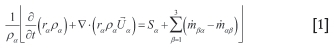
where rais the volume fraction of phase α, ραis the density of phase a, Uais the velocity of phase a, Sais the source term, mβ is the mass transfer from phase a to phase β, and mβa, is the mass transfer from phase β to phase a.
In the VOF model, only a single momentum equation is solved throughout the domain, and the resulting velocity field is shared among the phases. The momentum equation, shown below, is dependent on the volume fractions of all phases through the properties ρ and μ.
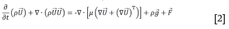
where ρ is density, U is velocity, μ is viscosity, and F is force.
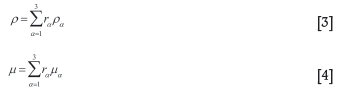
For the three-phase system studied in this paper, the volume-fraction-averaged density and viscosity are calculated as follows:
k - ε model
The multiphase flow in the Vanyukov furnace should be solved with a fluid-dependent turbulence model. Due to its low computational cost and good numerical stability, the homogeneous k - ε turbulence model was applied in this study. The isotropic eddy viscosity (μτ) is characterized by the turbulence kinetic energy (k) and its dissipation rate^), which are given by:
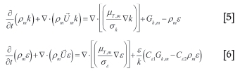
where, pmand Umare the mixture density and velocity, respectively, μτ,mis the turbulent viscosity, Gk,mis the production of turbulence kinetic energy, and akand σεare the turbulent Prandtl numbers for k and ε, respectively. The empirical constants appearing in the model are Cε1 =1.44, Cε2 =1.92, σk=1.0, and σε=1.3.
Geometry and simulation conditions
Physical model
A typical hypothetical Vanyukov furnace (Figure 1) was created using information in the literature (Hongjiu, 2001). There were 10 tuyeres on each side of the furnace to supply oxygen for the chemical reactions that take place in the slag layer. The tuyeres were located at the lower side of the furnace to ensure the high-speed enriched air could agitate the slag layer and provide enough oxygen for reaction inside the furnace.
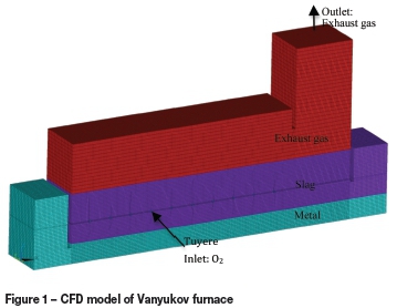
The main dimension parameters of the furnace were as follows: total length 19 m, total width 2.5 m, height 6 m, exhaust gas tunnel height 9 m, tuyere height 2.5 m, slag layer depth 3.5 m, metal layer depth 0.9 m, metal output region length 2 m, and slag output region length 2 m.
As the objective of this work is to study the multiphase flow inside the furnace, the following simplifications were made:
> Heat and mass transfer were not considered
> The furnace structure was simplified, and could be modified according to the actual furnace dimensions
> Granular raw material feeding and liquid metal discharge were not considered.
CFD modelling
In order to carry out the CFD calculation, a multi-purpose geometry containing the fluid phases (exhaust gas, slag, and liquid metal) was created in Pre-Processor of ANSYS®. The geometry was then meshed with hexahedral elements. The 3D hexahedral mesh, as shown in Figure 1, consisted of approximately 500 000 elements. Since the structure of this Vanyukov furnace is composed of rectangular modules, it could be meshed with a hexahedral-structured mesh with an excellent fit.
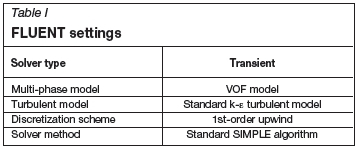
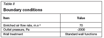
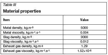
After the mesh was generated, it was imported into ANSYS CFX® and then read into FLUENT®. The corresponding solver-type settings, material properties, boundary conditions, and operation conditions must be specified properly. The detail settings for FLUENT are shown in Table I. The boundary conditions and material properties are shown separately in Table II and Table III.
Simulation procedure
Equations [1]-[6] were solved using the commercial solver Fluent 14.0. This package is a finite volume solver, using body-fitted grids. The pressure-velocity coupling was obtained using the SIMPLEC algorithm. For the time-dependent VOF and k - ε calculations, the explicit time marching scheme with small time step Δt=1x10⁻⁴ s was adopted. There were 443 264 control volumes, and the mesh was composed of hexahedral mesh elements. The computation of 6.6 seconds of operation of the furnace model consumed nearly 72 hours on a DELL® T7400 workstation with dual Xeon® CPUs (X5492, 3.4 GHz) and 16Gb memory running Windows® 7 Enterprise as operation system. This facility was provided by the Center for Innovation through Visualization and Simulation (CIVS) at Purdue University, Calumet in the USA.
Results and discussion
The numerical simulation of this unsteady three-dimensional and three-phase flow can reveal many characteristics that cannot be measured or observed directly in a running furnace, such as the fluctuation of the slag surface in the injection zone, melt movements in the sedimentation region, and displacement of the slag layer to the sedimentation region. It is important to find the correct distribution of the flow field, so that the furnace can operate efficiently with proper inlet speed and with proper metal and slag height.
Phase interface configuration
Distributions of the transient interfaces of three phases such as exhaust gas, metal, and slag at t=6.62 s are displayed in Figure 2. The 3D interfaces of overall slag-exhaust gas and slag-metal are presented in Figure 3, where the interface evolutions from t=0.29 s to t=6.62 s are listed separately.
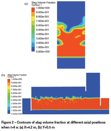
The dynamic pressure of air injected into the furnace is much greater than the pressure head due to the depth of slag. Therefore, there is a blow-through distance, which is an air jet termed the 'gas jet core' that initially enters the liquid, and bubbles are created in the molten slag as shown in Figure 3(a) to Figure 3(c). As the air bubbles impinge the slag intermittently, the wave at the interface of slag-metal and exhaust gas-slag is formed as a result of horizontal jet and upwelling flow in the air injection. The configuration of the slag surface at the interface between slag and exhaust gas is displayed in Figure 3, where the spout peak of combined flow can be observed. The slag becomes more active above the tuyere position, while it is more quiescent under it. As the flows are unsteady, the configurations of the phase interface are transient phenomena. The interface between the slag and metal is very quiescent, which is beneficial for metal separation. It is very important that with this flow field distribution, the chemical reaction can proceed to completion in the injection region, while the metal can settle in the sediment region with no stirring.
Velocity field distribution
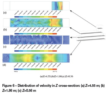
The velocity vectors and contours at the main section for all zones, including air, metal, and slag phases, are shown in Figures 4, 5, and 6 respectively.
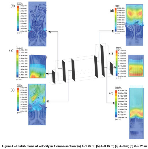
The flow pattern is in accordance with previous results (Hongjiu, 2001). Nevertheless, the flow pattern near the slag layer is very complex and unstable, and some vortices are observed. Variations in flow patterns are caused by the differences in physical properties of slag, air, and metal.
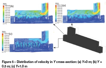
The enriched air injected from the tuyere into the slag layer could stirr the slag layer and accelerate the chemical reaction. The transient maximum values of exhaust gas, slag, and metal are 22.894 m/s, 70.00 m/s, and 0.0555 m/s respectively. Figures 4(f), 5, 6(c), and 6(d) show that the velocity in the slag settling region is very low. This could be due to the separate wall blocking the vigorous stirring in the injection region. The same phenomenon can also be found in the metal settling region. Therefore, by using this model, the height, spatial position, and thickness of the separate wall can be optimized to obtain the best flow pattern in the settling regions.
The oxygen-enriched air also causes the vortex movement and fluctuation. The air will push the slag towards the centre of the furnace and the upper interface. Several small vortices can be found in slag region, as shown in Figure 5. It is apparent that the velocity would be significantly reduced away from the tuyere zone. This is because of the huge density difference between the slag and enriched air (nearly 300). From this point of view, the model can also be used to optimize the tuyere structure and its operational configurations, such as tuyere diameter, tuyere angle, number and arrangement of tuyeres, and air flow rates.
Air flow distribution
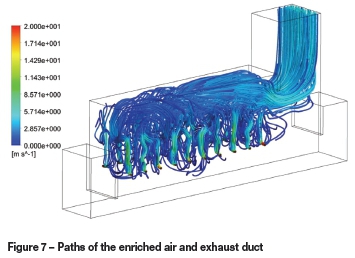
Figure 7 depicts the path lines of the enriched air. Most of the air is injected directly into the slag layer and escapes the from the slag-exhaust gas interface in the area located at nearly one-quarter of the width. This indicates that the current air speed (or tuyere pressure) and tuyere configuration is not good enough for the air to penetrate though the slag layer. The air flow above the slag is turbulent, which can be an important basis for determining the granular raw material distribution.
Spectrum analysis
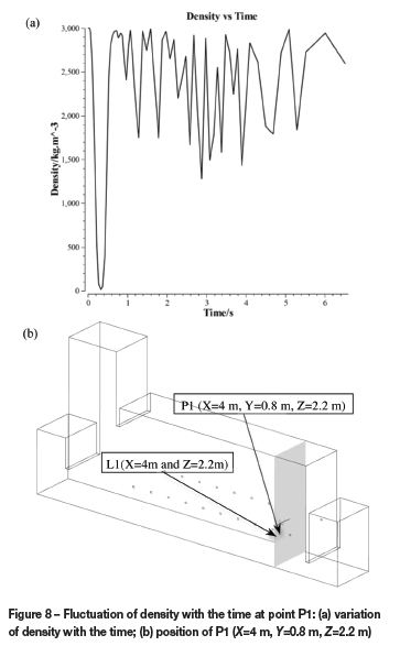
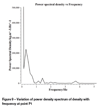
Wave formation at the slag/exhaust duct interface is another important factor for slag emulsification. It is known that as the wave fluctuation becomes stronger, the slag layer becomes easier to break up and be mixed with the granular raw material. The fluctuation of density with time and power density spectrum with frequency at the selected point P1(X=4 m, 7=0.8 m, Z=2.2 m) are shown in Figures 8 and 9 respectively. The fluctuation of density indicates that at this point the two phases (slag and air) are present in different instants. The density first drops to nearly zero in 0.3 seconds, then increases to 3000 kg/m3 and begins oscillating between 1500 kg/m3 and 3000 kg/m3. This indicates that the enriched air injected into the slag layer at first creates a hollow near the tuyere area, and then, as shown in Figure 3, stirs the slag layer vigorously. From the fast Fourier transform (FFT) of this density signal, we obtain the dominant frequency of the density variation, ω= 0.29 Hz, as shown in Figure 9.
Effect of air flow rate
Since the viscosity of the slag and the interface tension between slag and air are large, a large momentum is needed for air to overcome the interface tension and viscous force in the slag layer. This strong flow, which is directed horizontally initially and then upward and sideways, may drag the slag into the air flow, resulting in vigorous emulsification. Consequently, the effect of air flow rate is of interest. Using the same model, the flow fields with air flow velocities of 100 m/s, 130 m/s, and 160 m/s were calculated.
The time-averaged velocities at 13 points along the line L1(X=4 m and Z=2.2 m), as shown in Figure 8(b), are presented in Figure 10. The effect of air flow rate on slag velocity above the tuyere is significant. Along the line from the tuyere end to the furnace centre-line, the slag velocity at first increases to a peak value and then decreases. Secondly, the peak value positions are moved to the furnace centre with the increase in air flow rate. The slag velocity increases with increasing air flow rate. The peak mean velocity changes from 2.17 to 4.99 m/s as the flow rate of enriched air varies from 70 to 160 m/s.
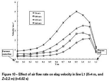
From this simulation, it can be demonstrated that the air flow rate should have a significant effect on slag emulsifi-cation through the effects of higher slag velocity and higher slag/exhaust duct interface wave frequency. In other words, the efficiency of the desulphurization is enhanced at higher air flow rates.
Future work will focus on the effects of furnace structural and operational parameters, such as the number of tuyeres, the angle of injection, the heights of the slag and metal layers, the dimension of the furnace, and the inlet of granular raw material. These parameters could all be investigated with the same model that was used in this work.
Conclusions
The main contribution of this work is to investigate the multiphase flow behaviour in the Vanyukov process. The following conclusions drawn from this study can be useful for improving furnace design and operation.
> When enriched air is injected into the slag layer, a gas plume is formed and bubbles are moved into the exhaust duct. The rising gas bubbles impinge the slag intermittently and break through the slag layer, resulting in splashing. Meanwhile, an unsteady wave is formed at the slag-exhaust duct interface
> Significant deformation of the slag layer occurs during enriched air stirring operation, and the slag becomes more active above the tuyere. The more complicated vortices in the slag layer, which are produced as a result of the different physical properties of the three phases and non-uniform external effects, were observed by simulation
> The injection flow rate of argon gas has a major effect on the mean slag velocity. The peak mean velocity increases from 2.17 m/s to 4.99 m/s as the flow rate of enriched air increases from 70 m/s to 160 m/s. A higher efficiency of desulphurization can be achieved at higher air flow rates
> The proposed model provides a method to optimize furnace structural and operational conditions, such as the number of tuyeres, the angle of injection, the heights of the slag and metal layers, the dimension of the furnace, and the inlet of granular raw material.
Acknowledgement
The authors would like to thank the Center for Innovation through Visualization and Simulation at Purdue University Calumet for offering this research opportunity and for assistance during the course of this work. The authors are also grateful for the financial support of the National Natural Science Foundation of China (51274241, 61321003).
References
Chen, Z. 2002. Numerical simulation of and on-line monitor of inner hearth-shaped of copper flash smelter Doctoral dissertation, Central South University. (In Chinese). [ Links ]
Fuentes, R., Ruz, P., Rosales, A., and Rojas. F. 2002. Fenomenologia del convertidor teniente. Minerals, vol. 57, no. 244. pp. 22-25. [ Links ]
Hongjiu, R. 2001. Bath smelting of nonferrous metals. Metallurgical Industry Press of China, Beijing. (In Chinese). [ Links ]
Kojo, I.V., Jokilaakso, A., and Hanniala, P. 2000. Flash smelting and converting furnaces: a 50 year retrospect. JOM, vol. 52, no. 2. pp. 57-61. [ Links ]
Kulkarni, A.A. and Joshi, J.B. 2005. Bubble formation and bubble rise velocity in gas-liquid system: a review. Industrial and Engineering Chemistry Research, vol. 44. pp. 5873-5931. [ Links ]
Lí, X.F., Chi, M., and Zhang, W.H. 2001. Numerical analysis and optimization of copper flash smelter. Master's thesis, Central South University. (In Chinese). [ Links ]
Lí, X.F., Mei, C., and Zhang, W.H. 2001. Simulation of copper flash smelter. Journal of Central South University (Nature Science Edition), vol. 32, no. 3. pp. 262-266. (In Chinese). [ Links ]
Liow, J.L. and Gray, N.B. 1990. Slopping resulting from gas injection in a Peirce-Smith converter: water modeling. Metallurgical Transactions B, vol. 21B, no. 12. pp. 987-996. [ Links ]
Lisienko, V.G. 1993. Methods of calculating heat transfer in metallurgical plants and control models. Journal of Engineering Physics and Thermophysics, vol. 64, no. 3. pp. 203-212. [ Links ]
Lisienkoa, V.G., Malikova, G.K.., Morozova, M.V., Belyaevb, V.V., and Kirsanov, V.A. 2012. Modeling heat and mass exchange processes in the Vanyukov furnace in specific operational conditions. Russian Journal of Non-Ferrous Metals, vol. 53, no. 3. pp. 272-278. [ Links ]
Mei, C., Xie, K., Chen, H., Lí, X., Chen, Z., Zhou, J., Wang, X., Mararu, T., and Zheling, G.E. 2003. Generating condition and applying results of high efficiency core in copper flash smelting. Nonferrous Metals, vol. 55, no. 4. pp. 85-88. (In Chinese). [ Links ]
Rao, Y.J. 2010. Experimental feeding segregation model of copper flash smelter. Master's thesis, Central South University. (In Chinese). [ Links ]
Real, C., Hoyos, L., Cervantes, F., Miranda, R., Palomar-Pardave, M., Barron, M., and Gonzalez, J. 2007. Fluid characterization of copper converters. Mecánica Computacional, vol. XXVI. pp. 311-1323. [ Links ]
Valencia, A. Rosales, M., Paredes, R., Leon, C., and Moyano, A. 2006. Numerical and experimental investigation of the fluid dynamics in a Teniente type copper converter. International Communications in Heat and Mass Transfer, vol. 33. pp. 302-310. [ Links ]
Valencia, A., Paredes, R., Rosales, M., Godoy, E., and Ortega, J. 2004. Fluid dynamics of submerged gas injection into liquid in a model of copper converter. International Communications in Heat and Mass Transfer, vol. 31, no. 1. pp. 21-30. [ Links ]
© The Southern African Institute of Mining and Metallurgy, 2015. ISSN2225-6253. Paper received Mar. 2015 and revised paper received Apr. 2015.

