


Services on Demand
Article
 English (pdf)
 Article in xml format
 Article references
Indicators

Related links
-
 Cited by Google
 -
 Similars in Google
Share

 Permalink
Journal of the Southern African Institute of Mining and Metallurgy
On-line version ISSN 2411-9717
Print version ISSN 2225-6253
J. S. Afr. Inst. Min. Metall. vol.115 n.5 Johannesburg May. 2015
GENERAL PAPERS
Hydraulic support instability mechanism and its control in a fully-mechanized steep coal seam working face with large mining height
Y. Yuan; S.H. Tu; F.T. Wang; X.G. Zhang; B. Li
Key Laboratory of Deep Coal Resource Mining, Ministry of Education of China, School of Mines, Mining Research Centre of China-Australia, China University of Mining & Technology, China
SYNOPSIS
Hydraulic support instability (HSI) is one of the most common causes of disasters in underground coal mining, posing a threat to the safety of mine workers and normal operation of the equipment. It is prone to occur in fully-mechanized mining faces with a large mining height (FMMLMH), especially when the dip angle of the coal seam is large. The key to controlling HSI is to deduce its mechanism and employ effective control techniques. This paper focuses on the analysis of HSI types, the key parameters and techniques to control HSI in FMMLMH, the establishment of a model of HSI in FMMLMH, and a multi-parameter sensitivity mechanical model of different HSI forms in the no. 7219 longwall face in Xutuan Coal Mine, Huaibei Mining Group, by using sensitivity analysis . The results show that HSI mainly presents in three forms: hydraulic support gliding (HSG), hydraulic support tilting (HST), and hydraulic support tail twisting (HSTT). The occurrence of the above three forms depends mainly on support anti-instability capability. In the no. 7219 longwall face, HSG and HST are the main two forms of HSI. The dip angle of the working face and the friction coefficient between floor and hydraulic support are the sensitive parameters for HSG, while HST is strongly dependent on the dip angle of the working face and the friction coefficient between roof and hydraulic support. By the applications of measures such as the oblique layout of the working face, cutting the floor into a step pattern, moving the support under pressure, and raising the setting load, the support stability was controlled effectively.
Keywords: fully mechanized mining, mining height, hydraulic support instability, sensitivity analysis, sensitivity parameter, control technique
Introduction
In 2013, coal production in China was 3680 Mt, accounting for more than one-third of the total world output. Production from thick seams accounts for 40-50% of national coal production. China is also the country with the highest incidence of mining disasters (Wu, Chen, and Long, 2012; Yuan, 2012). It is therefore essential to ensure mining safety in thick coal seams, especially concerning the prevention and control of hydraulic support instability (HSI), which poses a significant threat to the safety of mine workers and equipment (Tu, Yuan, and Yang, 2009). The most commonly used methods for mining thick coal seam (over 3.5 m), are fully mechanized mining with top coal caving (FMMTCC) and fully-mechanized mining with a large mining height (FMMLMH). Experience shows that recovery rate in FMMLMH is 10-15% higher than with FMMTCC. In recent years, with the development of mining equipment, FMMLMH technology has been widely used in thick coal seam mining. With its high recovery, FMMLMH has become a promising mining method for thick coal seams with a thickness less than 7.0 m (Ju and Xu, 2014).
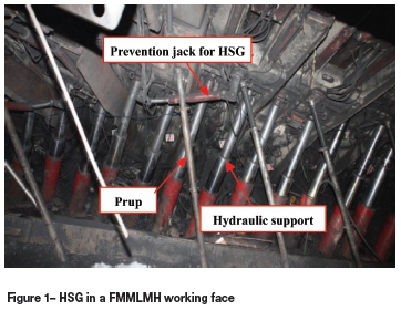
However, due to the large mining height and intense induced ground pressure, HSI often occurs in FMMLMH, especially in the working faces of steeply dipping coal seams. The poor stability of hydraulic support and difficulty of HSI control are the chief obstacles to the widespread implementation of FMMLMH technology (Yuan etal., 2010). Therefore, the control of HSI has become one of the most vital techniques in FMMLMH (Yuan et al., 2010; He, Qian, and Liu, 1997). Figure 1 shows hydraulic support tilting (HST) in a FMMLMH working face with a dip angle of 15°. Considerble research has been done on these issues. He et al. (1997) reported measures to avoid HST when the roof was caving or the hydraulic support was moving. Gong and Jin (2001) studied the relationship between HST and its influencing factors. They claimed that dip angle, mining height, the height of centre of gravity of the hydraulic support, and sequence of hydraulic support movement can influence HST significantly. Hua and Wang (2008) studied HS stability of the inclined FMMLMH. Tu and Yuan investigated the HSI mechanism and its control in a FMMTCC face in a steeply inclined seam (Tu et al., 2008; Yuan et al., 2008). Wang analysed the stability and applicability of hydraulic support with a two-prop shield (Wang, 2009; Liu, 2006).
Most of the above studies focused on the role of factors such as mining height, dip angle, working resistance of hydraulic support, the hydraulic support gravitational height, and sequence of hydraulic support movement on HSI. There is still a lack of relevance and effectiveness in HSI control technology; it is difficult to make proper adjustments to control HSI effectively for a particular case. This paper establishes a HSI mechanical model for FMMLMH through the critical stability conditions under three main instability forms - hydraulic support gliding (HSG), hydraulic support tilting (HST), and hydraulic support tail twisting (HSTT). The sensitive parameters were obtained via multi-parameter sensitivity analysis of HSI. Based on the results, control measures were carried out to tackle the HSI problem, and satisfying results have been achieved in field applications.
Mechanical model of HSI
HSI mainly takes the forms of HSG, HST and HSTT in a FMMLMH working face (Yuan et al., 2008). In order to derive the following equations, we assume that the forces imposing on the hydraulic support from the overburden and the floor are both uniformly distributed and the hydraulic support has a sequence number from the top to the bottom, such as 1, 2, 3..., n where n is the total number of hydraulic supports in the working face).
Hydraulic support gliding
As shown in Figure 2, due to the combined influence of hydraulic support weight W, the overburden resultant force P, the floor resultant force R, and the force between the adjacent support Tsand Tx, the hydraulic support tends to glide along the floor.
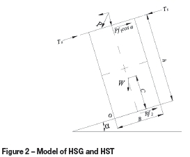
In order to avoid HSG, the anti-gliding force, which can be calculated from Equation [1] (Gong and Jin, 2001; Yuan et al., 2008; Yuan, 2011), should be not less than the gliding force.

where f1 is the friction coefficient between roof and hydraulic support,f2 is the friction coefficient between floor and hydraulic support, and α is the dip angle of the working face.
Assuming nhis the number of HSG, then the following situations apply.
(1) If nh=1 and Ts= Tx, i.e. the number of HSG is one, then Equation [1] can be divided into two cases:
Case 1: the hydraulic support does not contact the roof, i.e. P=0, then Equation [1] can be simplified as f2 tana, that is, the condition of hydraulic support remaining stable under its own weight.
Case 2: the hydraulic support contacts the roof, i.e. P>0. The critical angle of HSG ahlcan be obtained by Equation [1] as follows:
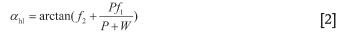
In general, f1 is affected by the structural integrity of the roof, and varies from 0.35 to 0.40;f2 is affected by floor water, float coal, and period weighting pressure, and varies from 0.22 to 0.82 (Gong and Jin, 2001).
According to Equation [2], ahlis proportional to P, f1and f2; ahlis inverse to W.
(2) If 1<nh<n and Ts#Tx, i.e. one HSG leads to the glide of adjacent supports, some supports in one certain area will glide. Assuming the first hydraulic support in the upper face glides, then Tx=0, and the induced force to the second hydraulic support can be calculated through Equation [3]:

Similarly, the gliding force induced by nhsupports is: nhThs(1~2). If there are k(k>1) supports forming a group beneath the nhth support, then the stability of the lower support group can be calculated through Equation [4]:
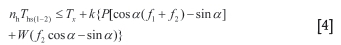
where Ths(1-2) is the gliding force from the first hydraulic support to the second.
According to Equations [3] and [4], the support group tends to glide with increasing α, nhand decreasing k.
(3) For the case nh=n, as all of the supports glide, the smallest anti-gliding force to maintain stability of the support is nThs(1-2), This case occurs only rarely and is easy to control.
Hydraulic support tilting
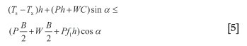
With the existence of an inclination component of force along the coal seam, the point of resultant force deviates from the lower edge of the support, which is the reason for the support tilt. As shown in Figure 2, on the condition of the moment-limiting balance of torque, the point of reacting force is O. In order to avoid HST, the anti-tilting torque should no less than the tilting torque, and can be calculated from Equation [5] (Gong and Jin, 2001; Hua and Wang, 2008; Yuan et al., 2008; Yuan, 2011):
where h is the mining height, B is the width of the HS base, and C is the height of the centre of gravity of the hydraulic support.
Assuming the number of HSTs is nd, then the following relationships can be derived.
(1) For the case nd=1, Ts= Tx, i.e. the number of HSTs is unity, this circumstance can be divided into three conditions.
(a) The hydraulic support does not contact the roof, i.e. P=0. Equation [5] can be abbreviated as which is the condition for hydraulic support to keep in balance in the free state.

(b) The hydraulic support contacts the roof, i.e. P>0. The critical angle of HST adlcan be derived from Equation [5] as follows:

According to Equation [6], the possibility of HST becomes smaller when the value of adlincreases under the following conditions: C decreases, f1 or B increases. There is an arctangent function relationship between 1/h and adl, and the suitable mining height decreases as adlincreases. That is why the hydraulic support tends to tilt when mining height increases, even in coal seams with a low dip angle as shown in Figure 1.
(c) The hydraulic support tends to tilt when hydraulic support falls or moves or when the roof is caving or broken. The loading pressure P then decreases, even to P=0. Then Equation [6] can be simplified as

i.e. the value of adl depends mainly on

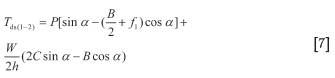
(2) For the case 1<nd<n, TS*TX, assuming the first hydraulic support of the upper face end tilts, the pressure on the second hydraulic support Tds(1-2) can be calculated by Equation [7]:
Similarly, the pressure transferred from the i-1th to the ith hydraulic support is defined as Tds((i-1)-i). Assuming there is a hydraulic support group formed by j supports beneath the ith hydraulic support, the stability of the hydraulic support group can be ensured through Equation [8]:
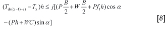
According to Equation [8], the hydraulic support becomes more stable with decreasing dip angle and increasing i and j.
(3) For the case nd=n, all the supports of the working face tilt. This situation is not tolerated in field production, and will not be discussed in this paper.
Hydraulic support tail twisting
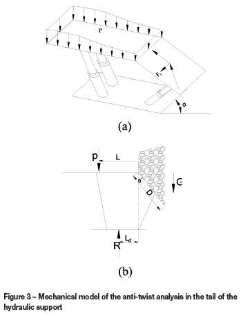
The height of the caving zone is much larger in a FMMLMH working face. The impulse force due to the caving rock after hydraulic support moves will cause the tail part of the hydraulic support to twist. If the anti-twist capacity of the hydraulic support is not enough to resist the lateral force caused by the component force due to caving in a down-dip direction, the tail of the hydraulic support will rotate and cause the support to tilt. An increase in the dip angle of the working face will aggravate this phenomenon.
As shown in Figure 3, L is the distance from the working line of the resultant force P from the roof to the end part of the top beam; Ld is the distance from the working line of the resultant force from the floor to the projection of the end part of top beam on the substructure; D is the length of the tail beam; and θ is the rotation angle of the tail beam.
The weight of caving rock on the hydraulic support tail beam G can be expressed as:
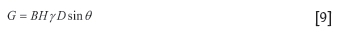
where H is the caving rock height, (metres) and γ is the average force per unit volume, (kN/m3);
The torque force of caving rock on the hydraulic support tail beam F1 can be expressed as:
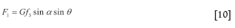
where f3 is the friction coefficient between caving rock and hydraulic support tail beam.
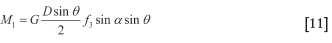
The torque M1 can be expressed as:
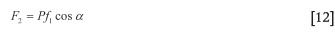
The anti-twist force along the roof F2 caused by P can be expressed as:
The anti-twist force along the floor F3 caused by R can be expressed as:
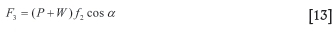
Then the anti-torque M2 can be expressed as:

In the case M2>M1, hydraulic support remains stable, and the critical angle of hydraulic support tail tilting anlcan be expressed as:
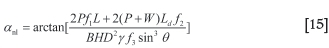
It is important to note that the above analysis depends on the axis being located in the midpoint of the top beam end. The axis position changes with the development of gliding. It may locate in the midpoint of the substructure end, and the analysis procedure is similar to the above.
According to Equation [15], the possibility of HSTT becomes smaller when the value of anl increases under the conditions as follows:f1 f2, P W, L, or Ldincreases, and B, H,f3, D, or θ decreases.
Based on the above analysis, the instability of one support is the cause of the unstable support in the working face. Whether the HSI is controlled effectively depends on the relationship between the critical instability angle and the dip angle of the working face. To evaluate the HSI quantitatively, a stability factor K is included:
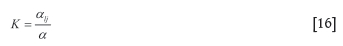
where alj is the critical instability angle and α is the dip angle of the working face. There are three possible scenarios, depending on the value of K:
K>1, the hydraulic support is stable
K=1, the hydraulic support is in a critical balanced state
K<1, the hydraulic support is unstable.
The value of K is the least value of three parameters Kh, Kd, and Kn, i.e.:

where Kh, Kd, and Knare the coefficients of anti-glide, anti-tilting, and anti-tail twisting for the hydraulic support, respectively:
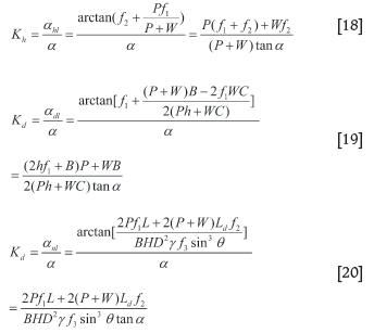
According to Equations [17]-[20], there are many factors affecting the HSI, including aJ1J2J3>, P, W, h, B, D, H, L, Ld and θ. It is a complex systematic problem to analyse the impact of the above factors on the HSI. Thus, it is necessary to conduct a quantitative analysis on the problem. Sensitivity analysis provides a new method of solving such a problem.
The sensitivity analysis method
The sensitivity analysis method (SAM) is a systemic analysis method focusing on the stability of a system (Zhang and Zhu, 1993; Zhu and Zhang, 1994; Hou et al., 2005). Assuming that there is a system, the characteristic U is determined by factors in the number of m2:β1={β1,β2...,βm}, U=φ(β1,β2...,βm). The system characteristic is under the criterion state β*=(βi,β2...,βm}. The definition of SAM is the trend and degree of deviation of U from U*, due to changes of each factor in its own possible range.
The first step of SAM is to establish a system model, i.e. forming a function relationship between the systematical characteristics and factors U=φ(β1,β2...,βτη). It is much better to define the function relationship with an analytic expression. For the complex system, numerical and diagrammatic methods are also appropriate to represent the function relationship. The establishment of the system model, conforming to the practical system to its greatest extent, is the key to the effective analysis of the parameter sensitivity.
It is necessary to provide a criterion parameter set, which is based on the specific questions. For example, the rock mass characteristics in a specific working face can be taken as a criterion parameter set to analyse the sensitivity of support stability to the given parameters. Sensitivity analysis can be conducted as the criterion parameter set has been defined. When the influence of parameter βk on the characteristic U is analysed, the remaining parameters are taken as criterion parameters and remain constant, βk varies in the possible range, and then U can be expressed:

indicates that U is very sensitive to βk, and βk can be termed a hypersensitive parameter. Otherwise, βk is a less-sensitive parameter.
For purposes of comparison with each property-different and unit-different parameter, a dimensionless sensitive factor is defined as follows:
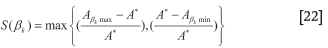
where S(βk) is the sensitivity of βk; A* is the corresponding characteristic value of criterion parameter set; and Aβk max and Aβk min are the maximum and minimum characteristic values varying in the range of βk, respectively.
Multi-parameter SAM of HSI in FMMLMH
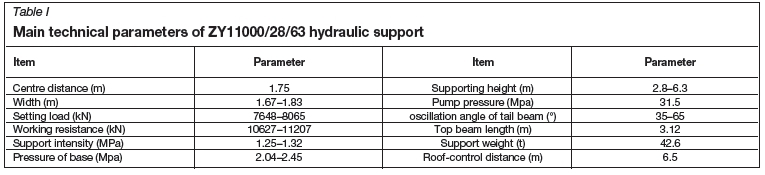
Tthe no.7219 working face in Xutuan Mine is used as an example. The coal seam thickness ranges from 4.0 to 6.5 m, with an average of 6.0 m, and the dip of the seam varies from 5° to 25°, with an average of 12°. The hydraulic support system used is ZY11000/28/63, and the main technical parameters are listed in Table I.
Eleven parameters are selected to analysee their influence on HSI, i.e. 0,f1,f2,f3, P, h, B, H, L, Ld, and θ. Using the geological conditions, the ground pressure observations at the working face, and the parameters in Table I, the average value and range of variation for each parameter are listed in Table II. The the average value and variation range of the 11 parameters are derived as follows. The parameters of 0 and h are obtained from the geological conditions of the working face; P and H are derived from field measurement of strata behavioer; B L, Ld, and θ are acquired from the technical parameters of the ZY11000/28/63 hydraulic support; and f1, f2, and f3 are obtained from Gong and Jin (2001), Yuan et al. (2008), and Yuan )2011).
The sensitive parameters, derived by using SAM, that affect the support stability in the no.7219 working face are listed in Tables III, IV, and V.
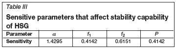
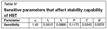
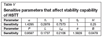
The parameters can be classified into three categories -sensitive parameters (S>0.5), less-sensitive parameters (0.1<S<0.5), and non-sensitive parameters (S<0.1) (Yuan, 2011; Zhang and Zhu, 1993).
In the anti-gliding condition, 0 and f2are sensitive parameters, and f1 and P are less-sensitive parameters. In the anti-tilting condition, 0 and f1 are sensitive parameters, with P being less sensitive and h, C, and B being non-sensitive parameters. In the anti-tail tilting condition, o,f2,f3, P, and θ are sensitive parameters,f1, H, L, and Ldare less-sensitive parameters, and B is the non-sensitive parameter. The relationships between the hydraulic support stability coefficient and the sensitivity are shown in Figures 4, 5, and 6, derived using the MATLAB software package.
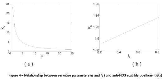
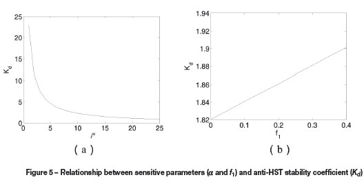
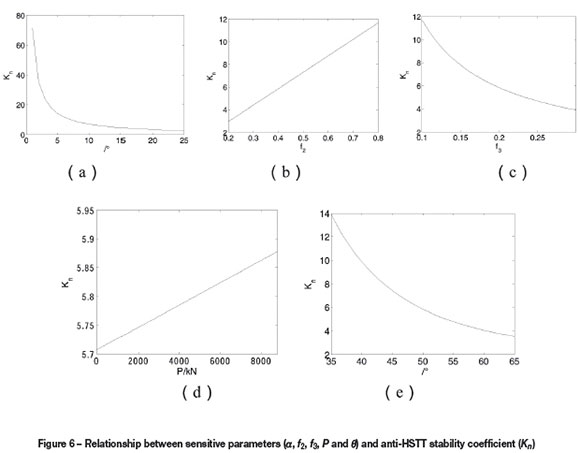
Figures 4, 5, and 6 indicate that:
> The anti-HSTT stability coefficient Knis relatively high, indicating that HSG and HST are the main HSI forms in the no.7219 working face
> The parameters of ο and f2have a greater impact on the anti-gliding stability coefficient Kh compared with f1and P. To avoid HSG, it is essential to increase the value of f2or to decrease the value of f1, for example, by making the layout of the working face with apparent dip and step pattern floor. Increasing the values of f1or P is also an effective way to prevent HSG,, for example, by moving the hydraulic support under pressure
> The anti-tilting stability coefficient Kdis fairly sensitive to f1, therefore emplacing the hydraulic support timeously after moving the support is an effective way to prevent HSG.
Conclusions
Hydraulic support instability (his) is likely to occur on steeply dipping coal seam working faces where fully-mechanized mining with a large mining height (FMMLMH) is applied. In order to control HSI, the mechanism of HSI in FMMLMH was modelled and interpreted, and the critical instability angles for the three HSI forms, i.e. hydraulic support gliding (HSG), hydraulic support tilting (HST), and hydraulic support tail twisting (HSTT) were obtained.
HSI in FMMLMH is a complex system issue influenced by 11 factors. Sensitivity analysis is an effective way to analyse the sensitivity of these factors and improve the effectiveness of hydraulic support stability control.
The multi-parameter sensitivity analysis of HSI in the no.7219 working face indicated that HSG and HST are the two main instability forms for HSI, as the anti-HSTT stability coefficient in this working face is relatively high. HSG is sensitive to the dip angle of the working face and the friction coefficient between floor and hydraulic support, while the dip angle of the working face and the friction coefficient between roof and hydraulic support are the main controlling parameters for HST. Through the above analysis, the oblique layout of the working face, step pattern of the floor, timely advance of support under pressure, and raising the setting load are the main technical measures to improve the support stability in the no.7219 working face, which contribute to the safety and efficiency of mining operations.
Acknowledgments
Financial support for this work was provided by the Priority Academic Program Development of Jiangsu Higher Education Institutions, and the Fundamental Research Funds for the Central Universities (No. 2014QNB32).
References
Gong, P.L. and Jin, Z.M. 2001. Research on influencing factors of tilt for fully-mechanized mining support with large mining height. Journal / Taiyuan University of Technology, vol. 32, no. 6. pp. 666-669. [ Links ]
He, F.L., Qian, M.G., and Liu, C.Y. 1997. Efficiency face bracket-rock security system. China University of Mining and Technology Press, Xuzhou. [ Links ]
He, F.L., Qian, M.G., Liu, X.F., Chen, L.W., and Li, C.F. 1997. Tilt characteristics and control conditions of high powered support. Journal o/ China University of Mining and Technology, vol. 26, no. 4. pp. 20-24. [ Links ]
Hou, Z.S., Li, X., Wang, S.J., and Lu, S.B. 2005. Sensitivity analysis of mechanical parameters to deformation of surrounding rocks for a tunnel in Jinchuan deposit II. Chinese Journal of Rock Mechanics and Engineering, vol. 24, no. 3. pp. 406-410. [ Links ]
Hua, X.Z. and Wang, J.C. 2008. Analysis and control of hydraulic support stability in fully-mechanized longwall face to the dip with great mining height. Journal of Coal Science and Engineering (China), vol. 14, no. 3. pp. 399-402. [ Links ]
Ju J.F. and Xu J.L. 2014. Structural characteristics of key strata and strata behavior of a fully mechanized longwall face with 7.0 m height chocks. International Journal of Rock Mechanics and Mining Science, no. 58. pp. 46-54. [ Links ]
Liu, J.F. 2006. Study on adaptability of shield support in large cutting height working face. Coal Science Research Institute, Beijing. [ Links ]
Tu, S.H., Yuan, Y., and Yang, Z. 2009. Research situation and prospect of fully mechanized mining technology in thick coal seams in China. Procedia Earth and Planetary Science, vol. 1, no. 1. pp. 35-40. [ Links ]
Tu, S.H., Yuan, Y., Li, N.L., Dou, F.J., and Wang, F.T. 2008. Hydraulic support stability control of fully mechanized top coal caving face with steep coal seams based on instable critical angle. Journal o/ Coal Science and Engineering (China), vol. 14, no. 3. pp. 382-385. [ Links ]
Wang, G.F. 2009. Research on mining technology with high mining height and development of powered support for high mining height. Coal Mining Technology, vol. 14, no. 1. pp. 1-4. [ Links ]
Wu P., Chen H., and Long R.Y. 2012. Relationship between coal output and safety in China. Disaster Advances, vol. 5, no. 4. pp. 551-556. [ Links ]
Yuan X.P. 2012. The characters and trend of accidents in the coal mining in China. Disaster Advances, vol. 5, no. 4. , pp. 866-869. [ Links ]
Yuan, Y. 2011.Stability control mechanism of support-surrounding rocks at fully mechanized mining face with great cutting height. China University of Mining and Technology, Xuzhou. [ Links ]
Yuan, Y., Tu, S.H., Dou, F.J., and Wu, Q. 2008. Support instability mechanism of fully mechanized top coal caving face with steep coal seams and its control. Journal o/Mining and Sa/ety Engineering, vol. 25, no. 4. pp. 430-434. [ Links ]
Yuan, Y., Tu. S.H., Wang, Y., Ma, X.T., and Wu, Q. 2010. Discussion on key problems and countermeasures of fully mechanized mining technology with high mining height. Coal Science and Technology, vol. 38, no. 1. pp. 4-8. [ Links ]
Zhang, G. and Zhu, W.S. 1993. Parameter sensitivity analysis and optimizing for test programs. Rock and Soil Mechanics, vol. 14, no. 1. pp. 51-58. [ Links ]
Zhu, W.S. and Zhang, G. 1994. Sensitivity analysis of influence of jointed rock parameters on damaged zone of surrounding rock. Underground Space, vol. 14, no. 1. pp. 10-15. [ Links ]
© The Southern African Institute of Mining and Metallurgy, 2015. ISSN2225-6253. Paper received Aug. 2012 and revised paper received Aug. 2014

