


Services on Demand
Article
 English (pdf)
 Article in xml format
 Article references
Indicators

Related links
-
 Cited by Google
 -
 Similars in Google
Share

 Permalink
Journal of the Southern African Institute of Mining and Metallurgy
On-line version ISSN 2411-9717
Print version ISSN 2225-6253
J. S. Afr. Inst. Min. Metall. vol.115 n.5 Johannesburg May. 2015
PYROMETALLURGICAL PAPERS
Interaction of dust with the DC plasma arc - a computational modelling investigation
Q.G. Reynolds
Pyrometallurgy division, Mintek
SYNOPSIS
The presence of dust and fume suspended in the freeboard region is a common feature of the operation of direct current (DC) plasma smelting furnaces. This occurs primarily as a result of the use of fine feed materials together with the open-arc, open-bath operation of such smelters, and is exacerbated by the high velocities and turbulent mixing of the gas in the vicinity of the arc jet. Dust and fume losses into the furnace off-gas system can be significant in some cases and may have economic, operational, and environmental impacts on the process. A computational modelling study is presented in which the concentration of dust material was considered as a continuous field subject to a governing partial differential equation. Settling behaviour was calculated as a function of particle size, local gas/plasma temperature, and other physical properties. Development of the coupling between the concentration field and a magnetohydrodynamic description of the arc is shown, and the resulting models were used to compute various aspects of the behaviour of the concentration field in the arc region for a variety of furnace conditions. Time-averaged as well as transient models of the arc were used to generate the results presented. Qualitative case studies produced several practical suggestions for furnace operation, including increased dust capture by the bath when feed ports are located closer to the electrode, and the possible effects of feed segregation in the furnace freeboard based on dust particle size and density.
Keywords: DC furnace, arc plasma, dust entrainment, continuumcomputational model, freeboard flow, arc flow
Introduction
The direct current (DC) arc furnace is employed as a metallurgical unit operation in a significant portion of the pyrometallurgy industry worldwide. While DC furnaces are traditionally used in the re-melting of steel scrap, they are becoming increasingly attractive for the smelting of raw materials to produce commodities such as ferrochromium, ilmenite, ferronickel, platinum group metals, magnesium, and others (Jones and Curr, 2006).
The layout of a typical DC furnace is shown in Figure 1. A cylindrical shell topped with a conical roof and lined with refractory materials forms the furnace vessel, and contains the molten process material. This molten bath typically consists of multiple liquid phases, with oxide (slag), alloy, and/or sulphide (matte) phases possible. Raw materials consisting of ores, reductants, and chemical modifiers are continuously fed into the vessel via feed ports at various locations in the roof. Single or multiple pre-baked graphite electrodes enter through the top of the roof. A power supply consisting of a transformer connected to a DC rectifier feeds electrical power to the furnace via the graphite electrode and an anode connection in the hearth.
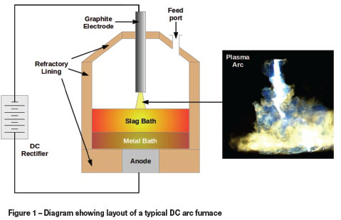
The electrical energy is converted into thermal energy in the plasma arc, which is the primary heating and stirring element inside the DC furnace. The arc consists of ionized freeboard gas containing a mixture of ions and free electrons, and is able to conduct electricity well. The electromagnetic forces interact with the plasma gas to accelerate and heat it, resulting in the formation of the arc - a high-temperature, high-velocity jet directed at the surface of the molten bath (Bowman, 1994). The arc may be thought of as the 'engine room' of the furnace, and improving the understanding of the physical behaviour of this region is invaluable for the improvement of current and future furnace designs.
One of the cited advantages of using DC furnaces for a particular process is that it is able to treat very fine materials directly, without the need for an agglomeration or briquetting stage prior to their introduction into the furnace (Jones and Curr, 2006). While it simplifies the furnace plant and operation considerably, this practice often raises the issue of dust carry-over - that is, how much of the dust from the feed material bypasses treatment in the furnace and is carried out of the off-gas ducts by entrainment in the gas flow. This is exacerbated in DC furnaces by the open-bath, open-arc nature of the operation, which provides no physical obstruction to the flow and circulation of gas in the freeboard.
Computational study of the dust behaviour in DC furnaces may be broken down into two broad areas - the freeboard flow problem and the arc flow problem. In the freeboard flow problem, one models the large-scale flow structures inside the entire furnace freeboard space and uses these models to predict dust bypassing from the feed port inlets to the off-gas outlets. In order to maintain computational economy, these models generally either ignore the presence of the arc or treat it as a simple jet, and use simplified fluid descriptions for the gas. A number of researchers have done valuable work in this area, predominantly focusing on engineering applications inside and around furnaces (de Jong and Mitchell, 2010; Ravary and Gradahl, 2010). In the arc flow problem, the influence of the plasma arc on the entrained dust in its immediate vicinity is modelled in detail. This generally requires a more sophisticated mathematical description of the arc in terms of magnetohydrodynamics (e.g. Szekely et al., 1983). The coupling between the entrained dust and the plasma gas must also be accounted for, and may be added to such arc models by modelling the dust particles' presence in several different ways, including continuum methods (Ranz et al., 1960) and particle methods such as discrete element modelling (Hager et al., 2013). Owing to the large driving forces and highly dynamic nature of the plasma arc, which can evolve on time scales of the order of milliseconds or less (Reynolds et al., 2010), study of the arc flow problem generally requires transient solution methods on high-resolution numerical meshes, and is considerably more computationally demanding even when considering only a small region of the freeboard space around the arc. As a result, it appears that little work has been done in the area to date.
In the present study a continuum computational model of the arc and dust concentration field is proposed, together with a discussion of various levels of coupling between the dust field and the arc plasma gas. The model is then used to examine the effect of various parameters on the dust distribution in and around the arc on a simplified, approximate two-dimensional geometry.
Model development
Equations describing the coupled momentum, energy, and electromagnetic fields are required in order to produce mathematical and computational models of plasma arcs. These have been described in some detail elsewhere (Reynolds et al., 2010), and are reproduced below.
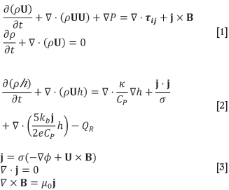
The Navier-Stokes and continuity equations [1] represent the conservation of momentum and mass respectively. In Equation [1], ρ is the plasma density, U is the velocity vector, P is the pressure field, tyis the viscous stress tensor (Newtonian fluids with viscosity μ are used in the present work), j is the electric current density vector, and B is the magnetic field vector.
The conservation of energy is governed by Equation [2]. In this relationship, h is the enthalpy of the plasma, κ is the thermal conductivity, CPis the heat capacity, σ is the electrical conductivity, kbis the Boltzmann constant, e is the electron charge, and QRis the radiation emission coefficient. The last three terms on the right-hand side of Equation [2] represent energy generation by ohmic heating, electron enthalpy transport, and energy loss from the plasma by radiation.
Maxwell's equations for electrostatics and magnetostatics (Equation [3]) govern the electromagnetic fields in the plasma. Here, φ is the scalar electric potential field, and μ0is the magnetic permeability of free space.
Under the assumptions of local thermodynamic equilibrium (Boulos et al., 1994), it is possible to describe the plasma fluid using a single temperature T. Enthalpy and all physical properties of the plasma are strongly temperature-dependent, and are therefore treated as variables in Equations [1]-[3]. This temperature dependence, together with the additional coupling via convection and source terms, results in a fully-coupled system in which all field variables depend to some degree on the others.
Modelling the dust field
In order to evaluate the distribution of dust in the arc region, a continuum approach is taken. If the local mass concentration of dust, c (mass of dust per unit mass of plasma gas), is taken as a field variable, then an additional transport equation for the mass conservation of dust may be written as shown in Equation [4].
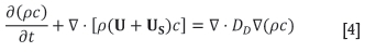
Here, US is the terminal settling velocity of the dust particles in stagnant plasma gas, and DDis a diffusion coefficient for the dust field. An assumption has been made in order to derive Equation [4], namely that the dust particles are fully entrained at the same velocity as the plasma gas at all times apart from the additional settling velocity. This implies that the dust particles are accelerated or decelerated to the local plasma gas velocity instantly, without any time lag due to the action of drag forces.
US may be calculated from the Stokes settling law (Lamb, 1932) as shown in Equation [5], assuming that the dust particles are sufficiently small that the Reynolds number remains below 1; this is generally the case for particles less than 1 mm in size falling through plasma gases.
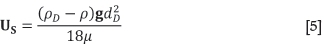
Here, pDand dDare the dust particle density and average diameter respectively, and g is the vector of acceleration due to gravity.
DD is somewhat harder to calculate accurately as it is generally a function of both molecular diffusion due to Brownian motion and collisions with particles in the plasma gas, and turbulent diffusion due to the eddy viscosity of the surrounding fluid. The molecular component may be estimated using the Stokes-Einstein relationship (Einstein 1905), shown in Equation [6].
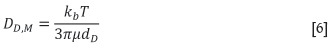
Evaluation of this equation for a range of typical plasma conditions gives values for DD,M of between 10-10 and 10-12 m2/s. These are so low as to be negligible, and the molecular diffusivity may be safely ignored.
In the case of the fully-transient and coupled dust models, in which Equation [4] is solved in lock-step with Equations [1]-[3], no turbulence closure model is used, and the solution is obtained on high-resolution meshes which attempt to resolve the majority of the turbulent flow scales directly. For these cases, the eddy diffusion component is calculated explicitly as part of the flow field and DDmay be taken as equal to DDM. However, in the case of time-averaged models with decoupled solution of the dust field (as are used for many of the results presented later), the turbulent eddy viscosity is not calculated directly and must be estimated from the time-averaged velocity field. For this purpose, the strain rate relationship familiar from large eddy simulation methods (Smagorinsky, 1963) is used, as shown in Equation [7].

Here, Sij is the strain rate tensor, which may be determined from the velocity field. 5l is a length parameter representing the size of the numerical mesh elements at any given location, and CS is a dimensionless empirical constant with value 0.16 - 0.2. Evaluation of Equation [7] gives a turbulent diffusivity field, and the total diffusivity to be used in Equation [4] may be calculated from DD= DDM+ DDT.
Coupling between dust, energy, and momentum fields
It is important to note that Equations [1]-[4] represent a system with only one-way coupling between the dust concentration field and the remaining variables. The arc affects the dust concentration distribution, but not vice versa. Such decoupling is valid for low dust concentrations, and has certain advantages; for example, in cases in which the settling velocity of the dust is very low, the time scales of the motion and evolution of the dust field may differ from those of the arc by an order of magnitude or more. In such cases, it is convenient to calculate time-averaged representative flow and temperature fields from Equations [1]-[3], and then solve Equation [4] separately using the time-averaged fields to study the evolution of c.
In general, however, the presence of a dust concentration field distributed through the plasma gas will affect both the momentum and heat transfer behaviour via two-way coupling. In order to study this effect, a simplified method of coupling is adopted based on the assumption of thermal and momentum equilibrium - that is, that the local temperature and velocity (apart from settling) of the dust particles are identical to those of the plasma gas. In reality, the dust particles have their own velocity and temperature distributions, with momentum and energy exchanged between them and the plasma gas resulting in acceleration and heating of the dust. However, this would not only introduce two additional fields requiring numerical solution (dust velocity and temperature) but also raise additional questions of how the transport between dust and plasma gas is to be modelled. As the purpose of the present study is to examine the gross qualitative effects of coupling between dust and arc, the simpler equilibrium approach was deemed justified, but this remains an open area for future work.
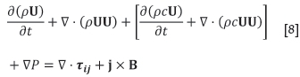
Under the equilibrium assumption for momentum, neglecting any additional momentum transfer to the plasma due to settling of the dust, and using the approximation that DD= DDM = 0 in the fully-coupled model, additional source terms representing the momentum of acceleration and deceleration of the dust field are included in the Navier-Stokes Equation [1] to give:
Similarly, under the equilibrium assumption for energy, source terms are added to Equation [2] to account for the transport of thermal energy contained in the dust field. Some re-arrangement and simplification using Equation [4] then leads to:
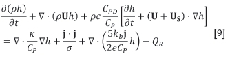
Here, CPDis the heat capacity of the dust particles, assumed to be constant.
Two-way coupling between the dust concentration field and the arc's momentum and enthalpy fields may then be realized by solving Equation [8] in place of Equation [1], Equation [9] in place of Equation [2], or both.
Model geometry and boundary conditions
While the model as developed extends naturally to both two-and three-dimensional cases, only 2D cases were considered in the present study. Time and resource limitations were the main reason for this, as the solution of high-resolution transient models of the plasma arc in three dimensions is extremely computationally intensive and time-consuming.
In order to study representative behaviour of the arc and associated dust fields, a 2D planar model region is generated by taking a slice through the centre line of the arc. Axisymmetry is not enforced in the model, and while this allows asymmetric structures and phenomena to evolve naturally, it is important to note that the planar nature of the model may be expected to result in some discrepancies between real three-dimensional furnaces and the model results. Such models should therefore best be viewed as 'arclike systems' which are capable of generating physically realistic and qualitatively similar behaviour, rather than quantitatively accurate engineering tools (Reynolds et al., 2010). The purpose of the present study is primarily qualitative, and the 2D approach was deemed to be an acceptable approximation.
The geometry used for the arc flow models is shown in Figure 2.
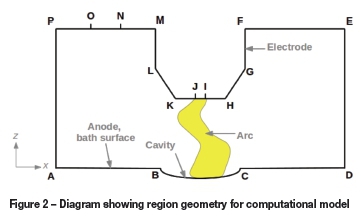
ABCD describes the surface of the molten bath, which acts as the anode in the system. In general, the thrust force of the arc deforms the bath surface, creating a cavity BC below the electrode tip. The graphite electrode surface is described by FGHIJKLM, with the cathode attachment spot IJ acting as the cathode and the root of the plasma arc jet. All other boundaries are open to the freeboard atmosphere, permitting inflow and outflow of plasma gases and dust. NO is the dust inlet, through which a fixed concentration of dust is introduced into the arc region.
Boundary conditions for the various fields in the model are required in order to complete the solution. These are shown in Table I.
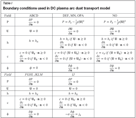
Here, P0 is the gas pressure in the furnace freeboard, typically atmospheric. hA, hIand hEare the plasma gas enthalpies at the anode surface temperature (taken as 3000K), inlet freeboard gas temperature (taken as 3000K), and electrode surface temperature (taken as the sublimation temperature of graphite, 4100K) respectively. c0is the inlet dust concentration, fixed for each simulation jk is the current density at the cathode spot, for which a value of 3.5 χ 107 A/m2 was used (Bowman, 1994).
Specifying the total current carried by the arc permits the calculation of the diameter of the cathode spot xij, using the given value of jk. Knowing the current and the distance from the cathode tip to the surface of the anode also permits the calculation of the thrust force generated by the arc (Bowman, 1994) and by analogy with turbulent gas jets, the shape and dimensions of the cavity surface BC (Cheslak et al, 1969). BC is treated as static in the present model. However, in general this zone will be characterized by a large amount of turbulent splashing and mixing. This would be expected to significantly enhance dust capture by the bath in this area, but a detailed examination of this phenomenon is left for future studies.
Numerical and computational implementation
In order to obtain numerical solutions of Equations [1]-[3] as well as the fully-coupled systems using Equations [8] and [9], a custom solver application was written in C++ code using the open source OpenFOAM v2.3.0 framework for field solutions of differential equations (OpenFOAM, 2014). OpenFOAM implements a generalized unstructured-mesh finite-volume method for defining conservation equations, and provides a number of accelerated and parallelized matrix solution techniques suitable for such problems.
Following the general approach of Sass-Tisovskaya (2009), an existing OpenFOAM CFD solver for incompressible flow using the Pressure Implicit with Splitting of Operators (PISO) predictor-corrector algorithm was heavily extended and modified to allow for general temperature-dependent plasma physical properties specified via lookup tables. Additional solvers for enthalpy and the electromagnetic fields were then constructed from scratch and incorporated into the standard PISO algorithm used for the velocity and pressure field solutions. Finally, a solver for the dust equation [4] was constructed and added to the algorithm, together with runtime switches to enable user activation or deactivation of the coupling behaviour.
Computational meshes for the problems were constructed and parsed into OpenFOAM format via Perl scripts using Gmsh v2.5.1 (Gmsh 2014), an open source geometry and mesh generation application.
The solver code was compiled and executed on a small computational cluster running Ubuntu Linux 12.04 LTS. GCC 4.6.3 (GCC, 2014) was used as the compiler, along with standard OpenFOAM wmake scripts. OpenMPI was used as the message-passing middleware. Post-processing and visualization was performed using ParaView v4.1.0 (ParaView 2014) together with the OpenFOAM wrapper script, paraFoam.
Results
Effect of the arc on the dust - one-way coupling
In order to study the effect that the flow field of the plasma arc has on the dust concentration field in the model region, a decoupled approach using time-averaged fields was taken. The procedure was as follows:
> Set up the model geometry and parameters
> Run the plasma arc model (Equations [1]-[3]) with no dust present for a short time period, until the initial conditions have decayed
> Generate time-averaged velocity and temperature fields using the results of the initial run
> Run the dust transport model (Equation [4]) for an appropriate length of time to study the evolution and development of the dust concentration field to steady state.
Base case model
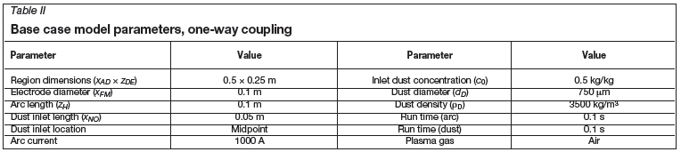
As a starting point for the one-way coupling study, a base case was defined. From this initial starting point, the sensitivity of the model to various design and material parameters could be studied. The parameters used for the base case model are shown in Table II. Dimension subscripts refer to Figure 2.
The dimensions of the region were chosen to match a typical small-scale pilot plant DC arc furnace facility. For the base case model, the dust inlet was located equidistant between the electrode and the edge of the model region. Dust concentrations in smelting furnace freeboards typically range between 0.1 and 1 kg/kg (Geldenhuys and Jones, 2009), and the diameter of suspended and bypassed dusts has been measured between 20 and 1000 μm (Guezennec et al., 2005; Rughubir and Bessinger, 2007). Tabulated physical properties as functions of temperature for air thermal plasmas were used (Boulos etal., 1994). The plasma arc model with no dust present was used to compute the first 100 ms of arc motion, with the final 25 ms being used for time averaging. The time-averaged fields were then used as input for the dust model, which was run for an additional 100 ms. An unstructured mesh of approximately 20 000 quadrangular elements was used for the simulations, in which high resolution was applied in regions of high shear and energy flux.
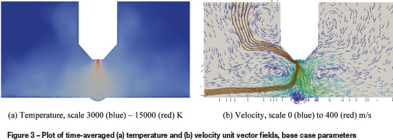
Time-averaged velocity and temperature fields of the arc are shown in Figure 3. It can be seen that time averaging of the rapid turbulent and chaotic dynamics of the arc column acts to produce a wide, conical temperature and jet velocity field which spreads out from the electrode tip into the space below. Figure 3b also shows the path of streamlines (in brown, including the settling velocity US) from the dust inlet at top left through the region and eventually out at the left boundary. It can be seen that the recirculation vortices generated around the arc result in substantial deformation of the streamlines, and much of the dust introduced at the inlet boundary is therefore likely to be entrained into the body of the arc jet.
Development of the dust concentration field c for the base case model is shown in Figure 4. It can be seen that the dust is very rapidly drawn into the high-velocity arc jet within 10 ms of entering the region. The fully developed steady-state dust concentration profile is shown in Figure 4d, with the majority of the dust passing through the arc jet before being carried out of the region by the strong flow adjacent to the bath surface. A smaller portion of the dust is captured by the bath surface.


The rate of dust convection or settling through the various boundaries can be studied by calculating the dust mass flux at the boundary surface (per linear metre in the y-direction, since the model domain is planar). Figure 5 shows the evolution of the rate of dust ingress or removal through the inlet (surface NO in Figure 2), bath (surface ABCD in Figure 2), sides (surfaces DE and AP in Figure 2), and top (surfaces EF, MN, and OP in Figure 2). The inlet flux is seen to be constant, as expected, while the dust fluxes through the various boundaries rise from zero to their steady-state values between 8 and 20 ms.
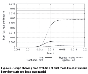
Once steady state is reached in the base case model, approximately 17% of the dust entering the region through the inlet is captured by the bath in the vicinity of the arc, 77.4% is bypassed out the sides of the region (mostly very close to the bath surface), and 5.6% recirculates back into the freeboard space above the arc region.
Effect of arc length
In order to study the effect of arc length (distance from tip of electrode to bath surface) on the dust transport model, several cases were set up and run keeping all parameters in Table II constant, with the exception of zHwhich was varied between 0.025 m and 0.2 m. Arc models were run for 100 ms (with 25 ms time-averaging) in order to generate averaged temperature and velocity fields. The dust transport model was then run for 100 ms for each case.
The resulting steady-state dust concentration fields for the two extreme cases are shown in Figure 6.
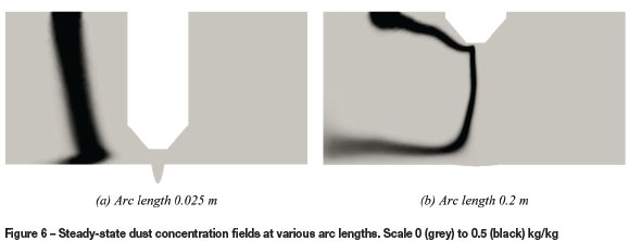
It is immediately obvious that running at shorter arc lengths results in far less entrainment of dust. This is primarily due to the reduction in size of the high-velocity recirculation zones around the arc - these zones scale in proportion to the length of the arc jet, and shorter arcs produce more compact velocity fields. Short arcs also produce a narrower, deeper cavity in the bath surface, which redirects much of the impinging gas flow back into the arc jet. As a result, dust is able to settle most of the way to the bath surface before interacting with the velocity field to any noticeable degree. The opposite is true for long arcs - these create very large vortex cells on either side of the arc jet, and the dust is almost immediately drawn into the body of the arc as it enters the region.
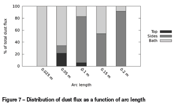
The dispersion of dust from the inlet to the boundary surfaces at steady state for the various arc length cases is shown in Figure 7. Increasing the arc length shows a general trend of increasing the dust bypassed out of the arc region, either via the side or top boundaries. Shorter arc lengths produce less bypassing and permit more capture of the dust by the bath, assuming all other geometry and material parameters remain constant.
Effect of arc current
The electric current carried by the arc is a key design and operation variable for DC furnaces. The effect of current on the dust behaviour was examined by varying the specified DC current while keeping all other parameters of the model as listed in Table II constant. Currents from 250 to 2000 A were used. Run-times for the arc model and time-averaging step varied from 400 ms (100 ms averaging) in the 250 A case to 50 ms (12.5 ms averaging) in the 2000 A case. The dust transport models were run for an additional 100 ms, sufficient for the fields to evolve to steady state in all cases.
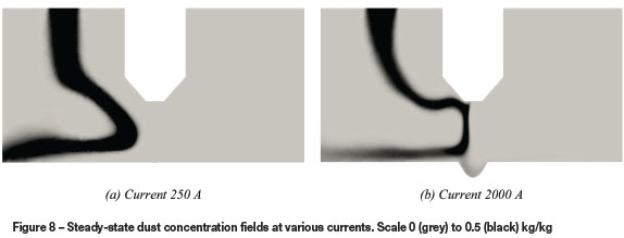
Steady-state dust concentration fields for the 250 A and 2000 A cases are shown in Figure 8. While both high and low currents show some degree of entrainment of dust into the arc jet and significant bypassing of dust material out of the region boundary at left, it can be seen that the lower velocities resulting from lower currents result in more pronounced settling of the dust cloud as it is convected. The higher currents, while entraining more of the dust and carrying it closer to the bath surface, result in such high velocities that the dust is rapidly carried out of the side of the model region before it gets a chance to settle onto the bath surface.
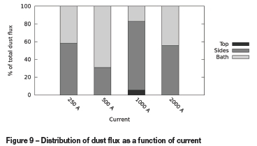
The steady-state dispersion of the inlet dust to various boundaries for the different arc current cases is shown in Figure 9. These results are somewhat noisy and it is difficult to discern an overall trend in the deportment of the dust flux, although comparing the result at 500 A to that at 1000 A suggests the possibility that higher currents may cause more dust to be bypassed out of the arc region. This may be expected given the fact that increasing current typically increases the velocities of the plasma in the arc (Reynolds et al., 2010), significantly reducing the residence time of the dust in the arc region and therefore reducing the time available for it to settle as it passes through.
Effect of dust inlet location
The location of the dust inlet, although a somewhat artificial concept in the present model, may be related back to the design of feed systems for DC furnaces and in particular the location of the feed ports in the furnace roof. With this in mind, the location of the inlet was varied while keeping all other parameters constant. Cases with the dust inlet adjacent to the electrode, and at the edge of the region, were examined. As before, arc models with no dust present were run for 100 ms, with the last 25 ms being used to generate time-averaged fields for input into the dust transport model, which was then run for an additional 100 ms.
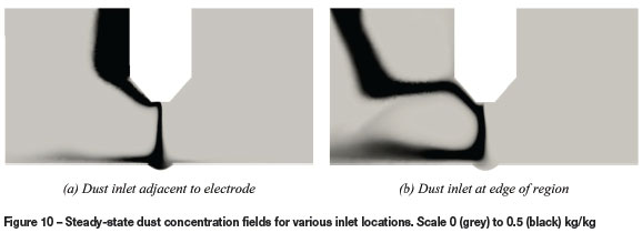
Steady-state dust concentration fields resulting from changing the location of the dust inlet are shown in Figure 10. It is interesting to note that moving the dust inlet does not affect the gross dust entrainment behaviour, namely that the falling dust column is drawn into the arc jet along the electrode surface at the centre of the furnace, accelerated toward the bath surface, and then convected outward. However, it can be seen that in the case of the adjacent inlet considerably more of the dust is captured by the bath surface before it leaves the model region.
This effect is quantified in Figure 11, showing dispersion of the dust to various boundaries in the model at steady state.
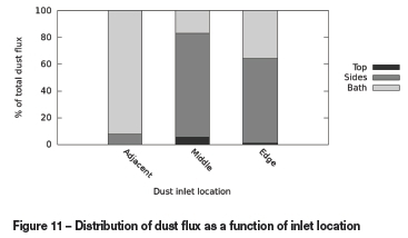
Location of the dust inlet close to the electrode results in far more efficient dust capture by the bath in the vicinity of the arc, with more than 95% settling to the bath surface in this case. As the inlet is moved further away, the dust has greater opportunity for interaction with recirculation structures in the plasma gas around the arc column, and as a result a much larger fraction of the incoming dust is captured into these recirculation structures and convected out of the side and top boundaries.
Effect of dust density
In general a dust stream entering a DC furnace as part of the raw material feed will be polydisperse, that is, it will consist of a distribution of particle types and sizes. It is therefore of some value to examine the effect of changing the dust properties, which affect the settling velocity Us, on the dust behaviour in the model. Dust density may be taken as a crude proxy for the composition of the particles - low densities of the order of 1500 kg/m3 are typical for carbonaceous reductants, while higher densities of 7000 kg/m3 or more are common for metallic components in the furnace feed. Different densities were tested in the model while keeping all other parameters constant as per the base case. The standard 100 ms arc time-averaging calculation with 25 ms of averaging was used, together with an additional 100 ms run time for the dust transport model.
Figure 12 shows the steady-state dust concentration profiles in the arc region for a low-density and a high-density dust.
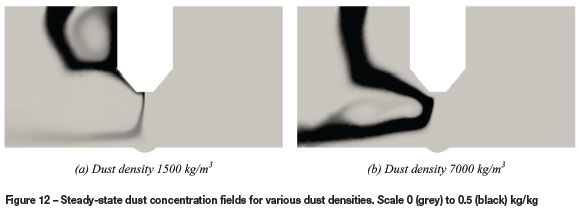
It can be seen that the low-density dust with its lower settling velocity remains largely contained in the recirculation cell near to the electrode surface - very little dust actually enters the arc column. In contrast, the high-density dust settles through the recirculation layer but is then strongly convected toward the side of the model region.
Distribution of the dust flux over the various boundary surfaces in the models at steady state is shown in Figure 13.
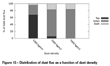
Lower density components in the dust stream were seen to remain entrained in the velocity field of the arc as they pass through the model region. In extreme cases, the low-density material may be circulated out of the top of the region and back into the freeboard space above. Generally, higher density components will still experience significant entrainment and bypassing, but they will tend to be carried out of the sides of the arc region close to the bath surface and are likely to settle out rapidly as the arc's velocity field decays away from the electrode.
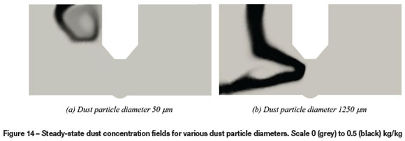
Effect of dust particle diameter
The polydisperse nature of the dust stream entering the arc region extends to particles of different diameter. This can drastically affect the dust behaviour in the region, as settling velocities scale with the square of the diameter as per Equation [5]. The dust transport model was used to examine the behaviour of a variety of dust particles with diameters ranging from 50 μm up to 1250 μm. As before, all other parameters as per Table II were held constant, with only the dust diameter dDvarying. 100 ms time-averaging runs to calculate the arc flow and temperature fields were used as before, together with additional 100 ms runs for each diameter model case.
Figure 14 shows the dust concentration fields at steady state for particles at the two extremes of size. Substantial differences are obvious; the smaller particles, unable to settle fast enough to overcome the recirculation flow that the arc creates in the surrounding plasma gas, are immediately entrained and convected out of the arc region by the medium-velocity gas flow near to the electrode. The larger particles, with much higher settling velocities, pass easily through the recirculation regions before being drawn toward the arc by the high-velocity flow in the vicinity of the main arc jet.
The distribution of the dust fluxes on the model boundary surfaces at steady state are shown as a function of the dust particle diameter in Figure 15.
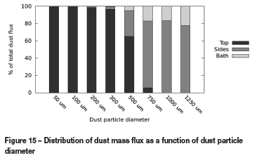
A distinct trend may be observed in the data, with smaller particles being so easily entrained by the flow patterns in and around the arc that they are completely bypassed out of the upper boundary of the region by convection. As the particle size increases past 500 μm, an increasing amount of dust is able to reach and settle on the bath surface, and the quantity convected through the top boundary drops away rapidly.
For a furnace feed stream containing dust across a wide range of size fractions, these differences in behaviour may result in substantially different fates for the different sizes.
Smaller particles will tend to become suspended in the freeboard gas and lost via the furnace off-gas system, while larger particles may be entrained into the arc region temporarily but will ultimately be captured by the bath surface or furnace sidewalls, possibly some distance from the arc itself.
Effect of the dust on the arc - two-way coupling
In order to study the feedback effects of the dust interacting with the plasma arc, the fully-coupled dust-arc model is used. Since for these cases the dust transport equation [4] cannot be decoupled from the plasma arc equations [3], [8], and [9], a single unified model algorithm is used to solve the momentum, energy, electromagnetic, and dust fields simultaneously. This improves the level of detail and temporal accuracy of the model results, but at the cost of significantly increased computational complexity and longer run-times.
Effect of coupling terms
For the initial study, base case parameters were kept identical to those used for the one-way coupling cases (Table II). The only additional parameter required for the two-way coupling case was an indicative heat capacity for the dust particles, which was taken as 1100 J/kgK for the typical oxide materials found in metallurgical ores. This value is approximated as constant across the range of temperatures typically encountered in plasma arcs, although in reality the dust particles would be in a molten or gaseous state at the higher temperatures.
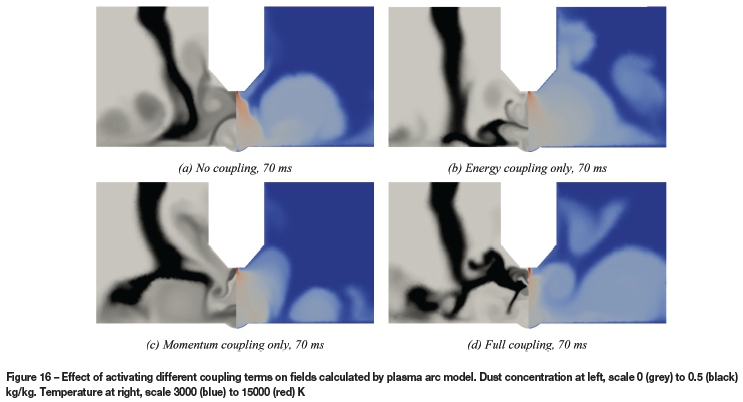
The effect of introducing different degrees of coupling was examined by starting with the model base case with no coupling, i.e. Equations [1]-[4], followed by cases with energy coupling only (Equations [1], [3], [4], and [9]), momentum coupling only (Equations [2], [3], [4], and [8]), and finally the fully coupled system. Each case was run for 100 ms of model time, using as initial conditions the established velocity, temperature, and electromagnetic fields from an earlier run of the arc model without any dust present.
Some example images showing the instantaneous temperature and dust concentration fields at the same time for each case are shown in Figure 16. It can be seen that although identical model parameters and initial conditions were used, activating various coupling terms results in the fields in the model producing very different patterns later in the simulation. Inspection of the general shape of the dust concentration field suggests that energy coupling has a relatively small effect, whereas momentum coupling changes the dust distribution patterns to a greater degree. Activating both coupling terms results in a visibly more turbulent and chaotically mixed dust concentration field, suggesting that there is increased transient behaviour of the flow and energy fields. This indicates that the presence of dust in the arc is able to affect its stability detrimentally in the model, by causing larger and more rapid fluctuations in the velocity and temperature fields.
This observation is borne out more quantitatively by examining the time dependence of the peak temperature, peak velocity, arc voltage, and dust flux at the bath surface for the various model cases. These results are shown in Figure 17.
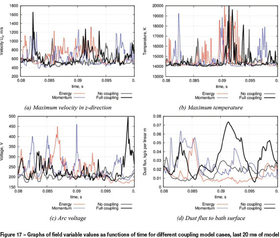
By comparing the solid grey line (one-way coupling only) on the graphs to the others, particularly the solid black line (full coupling), it can be seen that while the coupling terms are not large enough to appreciably change the average values of the fields over long time periods, they do significantly affect the variability of the fields over shorter periods. The arc model with full coupling is noticeably less stable than the model with one-way coupling only.
The entrainment of dust into a plasma arc may therefore be expected to produce an increase in high-frequency electrical noise in the furnace circuit, as well as an increased probability of arc extinction, due to the interaction between the dust and the arc.
Effect of dust inlet concentration in fully coupled model
In contrast to the one-way coupling case, the dust transport model in the fully coupled case is not linear due to the interaction terms in the momentum and energy equations. Therefore, the inlet dust concentration is able to affect the system behaviour in different ways - low concentrations would be expected to result in minimal effects, high concentrations in exaggerated effects. This was studied in the model with full coupling by varying the dust inlet concentration while keeping all other parameters constant, and examining the evolution of the various fields over time.
Visualizations of the dust concentration and temperature fields at different times in the models are shown in Figure 18.
The visualizations demonstrate that while the various fields in the fully coupled model start out with very similar distributions in space, different behaviour evolves as soon as the dust cloud begins to interact with the arc between 5 and 10 ms into the simulation.
There is considerable turbulent mixing by the high-velocity flow in and around the arc jet in both cases, but it is interesting to note that in the high-concentration case the arc jet is occasionally deflected away from the dust inlet at an angle of 45° or more (e.g. Figure 18d, cf. Figure 18b). This deflection is a transient phenomenon, but is observed to occur more frequently during the high-concentration case. A possible explanation for this behaviour is that as the dust concentration increases, it forms a physical and thermal barrier for the arc plasma due to the two-way coupling in the model. This results in the arc seeking the path of least resistance, deflecting away from the 'cold wall' that the falling column of dust represents.
The time dependence of the peak temperature, peak velocity, arc voltage, and dust flux at the bath surface for the different dust inlet concentration cases is shown in Figure 19.
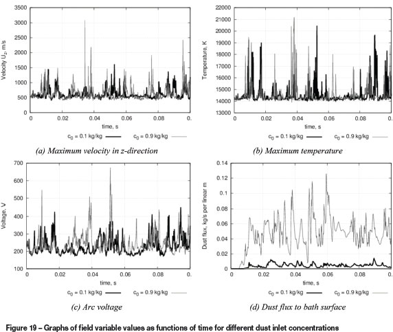
It can be seen - especially in the arc voltage and dust flux graphs - that increasing the dust inlet concentration produces greater fluctuations relative to the mean value in the fully coupled model over the course of the 100 ms simulation period. This indicates that more extreme and violent changes are occurring in the morphology of the fields that define the plasma arc. Together with the deflection behaviour observed, this would suggest that furnaces operating with high dust concentrations in the freeboard gas are likely to exhibit somewhat more instability and possibly even difficulties with arc extinction.
It is interesting to note that while both the average and peak arc voltages predicted by the high-concentration case are somewhat higher than those of the low-concentration case, it is a weakness of the present model that the effect is smaller than might be expected. From observations of real furnaces, the introduction of feed (together with dust) into the freeboard generally results in a significant increase in the resistance of the arc by both cooling of the plasma and increased turbulent flow.
Conclusions
Development of a continuum model for dust transport in the arc region of DC plasma arc furnaces was largely effective. The coupling between the governing equations of the plasma arc and the dust concentration field was developed in detail for cases of one-way and two-way coupling. The solvers were successfully implemented using the OpenFOAM finite volume method framework, and parallelized for distributed calculation on high-performance computing facilities.
The partially decoupled model was used to study the impact of a wide range of operational and material parameters on quantitative and qualitative aspects of the behaviour of the dust field. Dust particle properties in particular were seen to have a significant effect on the distribution of the dust through the arc region, as well as the quantity of dust bypassed relative to that captured by the bath surface. Location of the feed inlet was also seen to have a substantial impact on the dust circulation, with inlets located close to the electrode resulting in substantially improved capture of dust by the molten bath surface.
A brief examination of the effect of the dust on the arc via full coupling between the dust concentration field and the energy and momentum equations demonstrated that the presence of dust in the plasma gas could cause increased arc instability. Higher dust concentrations were seen to exacerbate this effect in the model results.
Much work remains to be conducted in this area. Extension of the coupling models to include separate temperature and velocity fields for the dust would improve the accuracy of the calculations. Inclusion of some form of empirical turbulence modelling (either Reynolds-averaged or large eddy simulation variants) would be valuable for scaling the simulations to larger, industrial-scale furnaces. Combining the DC plasma arc and dust models with a free-surface multiphase flow model to more accurately calculate the shape of the bath surface below the arc would also be of interest, in order to examine the role that the dynamics of the arc cavity plays in dust dispersal and capture. Experimental study by injecting dust into the vicinity of an operating arc would also be of great value in proving or disproving the hypotheses arising from the model results.
Acknowledgements
This work is published by permission of Mintek. Interactions with personnel and facilities at the CSIR/Meraka Institute Center for High Performance Computing and the CSIR Aeronautic Systems Group during the development phase of this work were useful and are greatly appreciated.
References
Boulos, M.I., Fauchais, P., and Pfender, E. 1994. Thermal Plasmas -Fundamentals and Applications, vol. 1. Plenum Press, New York. [ Links ]
Bowman, B. 1994. Properties of arcs in DC furnaces. Proceedings of the 52nd Electric Furnace Conference, Nashville, TN, 13-16 November 1994. pp. 111-120. [ Links ]
Cheslak, F.R., Nicholls, J.A., and Sichel, M. 1969. Cavities formed on liquid surfaces by impinging gaseous jets. Journal of Fluid Mechanics, vol. 36, no. 1. pp. 55-3. [ Links ]
De Jong, A. and Mitchell, D. 2010. New TiO2 slag plant for CYMCO using 30MW DC furnace. Proceedings of the 12th International Ferroalloys Congress, Helsinki, Finland. 6-9 June 2010. pp. 749-757. [ Links ]
Einstein, A. 1905. Über die von der molekularkinetischen Theorie der Wárme geforderte Bewegung von in ruhenden Flüssigkeiten suspendierten Teilchen. Annalen derPhysik (in German), vol. 322, no. 8. pp. 549-560 [ Links ]
GCC 2014. http://gcc.gnu.org/ [Accessed April 2014]. [ Links ]
Geldenhuys, I.J. and Jones, R.T. 2009. Four years of DC arc smelting of PGM-containing oxide feed materials at Mintek. Pyrometallurgy of Cobalt and Nickel2009. Proceedings of the 48th Annual Conference of Metallurgists at CIM, Sudbury, Ontario, 23-26 August 2009. pp. 415-427. [ Links ]
Gmsh. 2014. http://geuz.org/gmsh/ [Accessed April 2014]. [ Links ]
Guezennec, A.G., Huber, J.C., Patisson, F., Sessiecq, P., Birat, J.P., and Ablitzer, D. 2005. Dust formation in electric arc furnace: birth of the particles. Powder Technology, vol. 157, no. 1-3. pp. 2-11. [ Links ]
Hager, A., Kloss, C., Pirker, S., and Goniva, C. 2013. On the formation of blast furnace raceways - a combined experimental and open source CFD-DEM investigation. Proceedings of MEI Computational Modelling '13, Falmouth, UK, 18-19 June 2013. [ Links ]
Jones, R.T. and Curr, T.R. 2006. Pyrometallurgy at Mintek. Proceedings of Southern African Pyrometallurgy 2006, Johannesburg, South Africa, 5-8 March 2006. pp. 127-150. [ Links ]
Lamb, H. 1932. Hydrodynamics. 6th edn. Cambridge University Press. [ Links ]
OpenFOAM. 2014. http://www.openfoam.org [Accessed April 2014]. [ Links ]
ParaView. 2014. http://www.paraview.org/ [Accessed April 2014]. [ Links ]
Ranz, W.E., Talandis, G.R., and Gutterman, B. 1960. Mechanics of particle bounce. AIChE Journal, vol. 6, no. 1. pp. 124-127. [ Links ]
Ravary, B. and Gradahl, S. 2010. Improving environment in the tapping area of a ferromanganese furnace. Proceedings of the 12th International Ferroalloys Congress, Helsinki, Finland, 6-9 June 2010, pp. 99-107. [ Links ]
Reynolds, Q.G., Jones, R.T., and Reddy, B.D. 2010. Mathematical and computational modelling of the dynamic behaviour of direct-current plasma arcs. Proceedings of the 12th International Ferroalloys Congress, Helsinki, Finland, 6-9 June 2010. pp. 789-801. [ Links ]
Rughubir, N. and Bessinger, D. 2007. Furnace dust from Exxaro Sands KZN. Proceedings of the 6th International Heavy Minerals Conference: 'Back To Basics', Hluhluwe, South Africa, 9-14 September 2007. pp. 43-48. [ Links ]
Sass-Tisovskaya, M. 2009. Plasma Arc Welding Simulation with OpenFOAM. Licentiate Thesis, Department of Applied Mechanics, Chalmers University. [ Links ]
Smagorinsky, J. 1963. General circulation experiments with the primitive equations I. The basic experiment. Monthly Weather Review, vol. 91, no. 3. pp. 99-164. [ Links ]
Szekely, J., McKelliget, J., and Choudhary, M. 1983. Heat-transfer fluid flow and bath circulation in electric-arc furnaces and DC plasma furnaces. Ironmaking and Steelmaking, vol. 10, no. 4. pp. 169-179. [ Links ]
© The Southern African Institute of Mining and Metallurgy, 2015. ISSN2225-6253. This paper was first presented at the, Pyrometallurgical Modelling Principles and Practices, 4-5 August 2014, Emperors Palace Hotel Casino Convention Resort, Johannesburg.

