


Services on Demand
Article
 English (pdf)
 Article in xml format
 Article references
Indicators

Related links
-
 Cited by Google
 -
 Similars in Google
Share

 Permalink
Journal of the Southern African Institute of Mining and Metallurgy
On-line version ISSN 2411-9717
Print version ISSN 2225-6253
J. S. Afr. Inst. Min. Metall. vol.115 n.5 Johannesburg May. 2015
PYROMETALLURGICAL PAPERS
Modelling of fluid flow phenomena in Peirce-Smith copper converters and analysis of combined blowing concept
D.K. ChibweI; G. AkdoganI; P. TaskinenII; J.J. EksteenI
IUniversity of Stellenbosch, Process Engineering Department, South Africa
IIAalto University, Department of Material science and Engineering, Finland
IIICurtin University, Department of Metallurgical Engineering, Australia
SYNOPSIS
This investigation consists of a numerical and physical modelling exercise on flow patterns, mixing, solid-liquid mass transfer, and slag-matte phase distribution in a 0.2-scale cold model of an industrial Peirce-Smith converter (PSC). Water, kerosene, air, and sintered benzoic acid compacts were used to simulate matte, slag, injected gas, and solid additions into the PSC. The 2D and 3D numerical simulations were carried out using volume of fluid (VOF) and realizable k-ε (RKE) turbulence models to account for the multiphase and turbulence nature of the flow respectively. These models were implemented using the commercial computational fluid dynamics numerical code FLUENT. Numerical and physical simulations were able to predict, in agreement, the mixing and dispersion characteristics of the system in relation to various blowing conditions. Measurement of mass transfer indicated that fluid flow in the PSC is stratified. Blowing configurations and slag volume both had significant effects on mixing propagation, wave formation, and splashing. As a potential process alternative to increase conversion efficiency, we propose a combined blowing configuration using top lance and lateral nozzles. The numerical simulations were conducted on combined as well as lateral blowing conditions, and the results of the combined concept are encouraging.
Keywords: Peirce-Smith converter, combined blowing, CFD, mixing, splashing
Introduction
Peirce-Smith converters (PSCs) have been used in the copper and PGM smelting industries for more than a century for the purpose of removing iron and sulphur through oxidation reactions to obtain blister copper and converter matte respectively. This process step is referred to as conversion (Liow and Gray 1990; Real et al., 2007). The conversion process used in removing iron and sulphur from matte is a complex phenomenon involving phase interactions, many chemical reactions, associated heat generation, as well as product formation (Kyllo and Richards, 1998a). The PSC is a cylindrical horizontal reactor (circular canal geometry) where air at subsonic velocity (Mach < 1) is injected into matte through submerged lateral tuyeres along the axis of the converter (Gonzalez et al., 2008). The converting process is semi-continuous and autothermal. Since there are chemical reactions taking place with products being formed, quality and quantity of mixing are important.
Mixing promotes chemical reactions, removing the products from reaction sites, and minimizes temperature and the composition inhomogeneities caused by cold solid additions in the form of scrap, process ladle skulls, reverts, and fluxes, which are inherent to the converting processes. Due to generation of turbulence in the converter, mixing may also aid inclusion agglomeration, coalescence, and flotation of impurities, thus improving converter efficiencies (Gray et al., 1984).
Mixing is important in submerged pyrometallurgical gas injection systems and has attracted much attention. Most research on mixing and injection phenomena in gas/liquid multiphase systems has been conducted for steelmaking and ladle metallurgy (Castillejos and Brimacombe, 1987; Kim and Fruehan, 1987; Sahai and Guthrie, 1982; Sinha and McNallan, 1985; Stapurewicz and Themelis, 1987). Turkoglu and Farouk (1991) defined mixing intensity and efficiency in terms of the time required to achieve a well-mixed bath -which is the time required, after the introduction of tracer, for tracer concentration at every nodal location in the system to reach a value that varies by no more than ±5% .
Despite substantial PSC operational experience, there has been insufficient research on the process engineering aspects. Mixing and mass transfer in the converter are key process parameters that have been studied very little. Due to the similarity of the basic concepts in ladle injection and the PSC, the core tenets of the work on ladle injection have been adopted in research into process characterization of the PSC in an effort to address the challenges in productivity (Gray et al., 1984; Hoefele and Brimacombe, 1979; Vaarno et al., 1998). Physical and numerical models of the PSC have been developed to study multiphase fluid flow phenomena (Liow and Gray, 1990, Vaarno et al., 1998; Koohi et al., 2008; Ramirez-Argaez, 2008; Rosales et al., 2009; Valencia et al., 2004, 2006). These models have been used in pyrometallurgical operations to establish functional relationships of process variables such as reaction kinetics (Kyllo and Richards, 1998b), injection dynamics (Schwarz, 1996; Rosales et al., 1999; Valencia et al., 2002) and fluid flow behaviour (Han et al.,2001; Real et al., 2007; Valencia et al., 2004). Despite the amount of numerical and experimental work on the fundamental phenomenon of multiphase flow, little effort has been addressed to the understanding of the combined effect of blowing rates and the presence of a slag phase on the overall mixing performance of the converter. If proper mixing is not achieved in the reactor, the fundamental consequences are chemical, thermal, and particulate inhomogeneities, resulting in undesirable variability in the final product composition.
PSC process reactions are highly exothermic in nature and high temperatures can result, depending on the grade of charged matte. It has become common practice to add cold flux and scrap, process reverts, and ladle skulls in order to control the thermodynamics of the process. The solid-liquid mass transfer step may play an important role in the process performance and attainment of thermal and chemical bath homogeneity. The mechanism of dissolution of the cold additions and behaviour of active sites within the converter are not well understood. Rates of dissolution can be assumed to affect the thermal state of the converter and hence to be a factor that affects the turnaround time of the converter processing. Establishing a stable functional state of the converter, and fully developed categorization of flow fields, is therefore necessary for effective process control.
As mentioned above, the literature pertaining to solid-liquid mass transfer in ladle metallurgy is fairly comprehensive. Despite this, no in-depth studies have been found that address this critical subject of solid-liquid interactions in PSCs. The only source close to the subject is the study by Adjei and Richards (1991), who investigated gas-phase mass transfer in a PSC using a physical model. Their work revealed pertinent information relating to oxygen utilization efficiency in the converter.
In the PSC, the injected air has two main functions, which are to supply oxidant and energy to stir the bath. Energy is supplied in three forms, namely kinetic, buoyancy, and expansion. Energy and oxidant supply affect the chemical and physical processes in the converter such as converting rate, oxygen efficiency, dispersion of matte and slag, mixing, heat and mass transfer, slopping, splashing, and accretion growth (Haida and Brimacombe, 1985; Valencia et al., 2004). Again, little effort has been addressed to the understanding of the complex phase interactions of the three-phase system in terms of volumetric dispersion in relation to the flow conditions presented by tuyere-specific power. Dispersion is a subject that needs further understanding as substantial amounts of valuable metal are lost due to entrapment; a situation that leads to the incorporation of slag-cleaning systems in copper production circuits (Moreno et al., 1998; Warczok et al., 2004).
In this work, firstly the dependence of mixing on volumetric air flow rate and simulated slag quantities for different matte and slag levels is investigated using a combination of physical and numerical modelling. Secondly, we aimed at monitoring different regions in the PSC for solid-liquid mass transfer analysis. This was carried out through calculation of the localized turbulence characteristic and mass transfer coefficient. The dependence of these two mass transfer parameters on operating system variables such as air flow rate and the presence of a second phase (slag) were investigated. Thirdly, we investigated the effect of volumetric gas flow rate in the dispersion and interaction of matte and slag phases in the PSC.
Due to the scarcity of quantitative research work to date on PSCs, an overall strategy was devised to explain and evaluate experimental results using numerical simulation of the converter through computational fluid dynamics (CFD) software. Vaarno et al. (1998) and Valencia et al. (2004) evaluated the applicability of mathematical formulation to the PSC process using cold model experiments and established velocity vector fields. In similar studies, Vaarno et al. (1998) and Valencia et al. (2004) investigated the influence of the Froude number on bath mixing, jet stability, and splashing in a PSC using mathematical formulation and cold model experiments. This work presents a first attempt to study the dispersion and interaction of phases in the PSC.
In order to attain our physical modelling objectives, a 0.2-scale water bath physical model with equivalent properties to the generic industrial PSC used in copper smelters was designed using similarity principles. Geometric, dynamic, and kinematic similarity criteria were used in the design for equivalency between prototype and model, since hydrodynamic studies on fluid flow are not concerned with thermal and chemical similarity effects (Mazumdar, 1990). The modified Froude number, which represents fluid flow dominated by inertial and gravitational forces, was used for dynamic similarity. The molten liquid phases in the real PSC (matte and slag) were simulated in the model with water and kerosene respectively due to kinematic similarity.
In support of the physical modelling work, we also used isothermal transient multiphase 2D and 3D CFD numerical simulations. The CFD numerical code FLUENT software was used to solve the transient Navier-Stokes equations. The realizable k-ε turbulent model and volume of fluid (VOF) method were used to model the turbulence nature and multiphase flow respectively.
Experimental methods
Physical model description
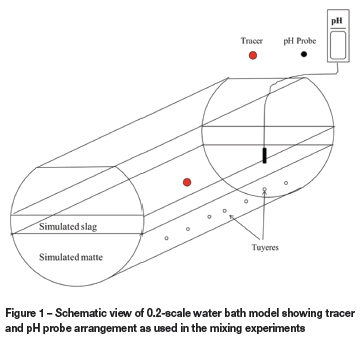
The physical experiments for mixing, mass transfer, and phase dispersion measurements were conducted in a 0.2-scale PVC water bath model as shown in Figure 1. A polyvinyl chloride 2.5 inch cylindrical manifold served as a reservoir for compressed air at a constant line pressure supply of 5.5 bar. An inline VPFlowMate digital mass flow meter, which uses the thermal mass flow principle, was used to measure the volumetric flow rate of compressed air into the model. The flow meter was powered with a low-voltage limited current power source. This water model also formed the basis for the numerical simulations.
Similarity using dimensionless numbers is the key feature in the development of physical models. In the design process, geometry, kinematic, and dynamic similarities were observed through consideration of dimensionless numbers. Geometric similarity was observed using a scale factor on all physical dimensions, and dynamic similarity achieved through the modified Froude number, NFr, which resembles fluid flow dominated by inertial and gravitational forces. Kinematic similarity was observed between the PSC and model through the Morton number, NMo, which incorporates surface tensions, viscosities, and densities of the fluids. Modified Froude and Morton numbers are given in Equations [1] and [2] respectively:
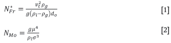
where vt(m s-1) is the tuyere tip exit velocity, pl (kg m-3) is the liquid density, pg(kg m-3) is the gas density, g (m s-2) is the gravitational acceleration, do(m) is the tuyere diameter, μ (Pa s) is the dynamic viscosity, and σ (N m-1) is the surface tension of liquid.
The condition of similarities yielded the dimensions, blowing conditions, and fluid physical properties as summarized in Table I.
For mixing time measurements, a tracer dispersion technique was used where sulphuric acid was injected in the centre of the model at 100 mm below the water (simulated matte) level and monitored by a pH meter placed directly opposite the tracer injection point at 100 mm from the converter circular wall. The midpoint of the bath was taken as the tracer injection point for simulation of the converter inputs charging point, which is situated in the centre of an industrial PSC. Figure 1 shows the tracer and pH meter positioning as used in this experimental set-up. Water was filled to a total constant height of 270 mm, which is 39% filling capacity. Kerosene was used to simulate the slag layer.
The kerosene-to-water height ratio was varied from 0% to 40% at five equidistant intervals. Air volumetric flow rate was varied from 0.00875 to 0.01375 N m3 s-1, which represents a typical scaled-down industrial operation range. A matrix of 25 experiments was designed and each experiment was repeated five times under the same conditions. An average mixing time was taken, which was within 10% standard deviation on all experimental conditions. The response was defined as the time taken to achieve uniform and homogeneous steady-state concentration of the bath after introducing a tracer. Decay in pH concentration to a value ±0.01 pH units represented 99% mixing in this work. In the numerical simulations for mixing time measurements, a region was adapted in the same location as the tracer injection point in the physical experiments where acid was patched with a volume fraction of 1. A custom field function was formulated at the position analogous to the pH position, measuring the mole fraction of tracer species concentration as a function of flow time. This was achieved through solving the species transport equation. Mixing was considered complete when the species concentration reached a stable value.
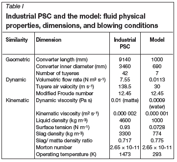
For solid-liquid mass transfer experiments, the benzoic acid cylindrical samples were 81 mm long and 38 mm diameter on average. To promote radial dissolution and minimize the end effects, the samples were enclosed between two thin mild steel washers on both ends. The benzoic acid compacts were mounted to a steel grid fastened with threaded rod. A total of eight samples were inserted in the converter model at a predetermined depth for every experimental run, as shown in Figure 2. The sample labelling convention used here shows sample number and submergence referenced from the converter bottom. Due to the shallow matte depth relative to the sample lengths, only two sample depths were considered in these experiments, namely 50 mm (H50) and 90 mm (H90) from converter bottom respectively. The samples were introduced and immersed into the water bath after the air volumetric flow rate had reached a steady-state value within ±1% of the required value and the simulated slag thickness had been added. The samples were simultaneously subjected to four cycles of 900 seconds' treatment, during which they were removed at intervals, thoroughly dried, and weighed. The weight loss was converted into equivalent radii so as to calculate mass transfer coefficients. The air flow rates varied from to 0.0025 to 0.01125 N m3 s-1. Two simulated slag thicknesses, 54 mm and 108 mm, were used in the experiments, representing 20% and 40% of simulated matte height respectively. These two simulated slag volumes will be referred to as 'low simulated slag' and 'high simulated slag' volumes in the text.
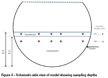
In the phase dispersion measurements, the physical model was filled with water and kerosene to a total height of 285 mm, which is 41% filling capacity. The kerosene-to-water height ratio was kept at 0.267. Air volumetric flow rate was varied from 0.0085 to 0.0142 N m3 s-1 with five levels representing 75, 90, 100, 110, and 125% of the typical equivalency model volumetric flow rate of 0.0113 N m3 s-1. For a specific experimental set-up run, at the end of experiment all syringes positioned at relevant sampling points as shown in Figure 3 were pulled at once and the contents were poured into measuring cylinders. The emulsion in the measuring cylinders were given sufficient time for complete phase separation, and the volumes of water and kerosene were read directly. Dispersed phase hold-up was calculated as the volumetric percentage of slag or matte with respect to the total volume of emulsion at a certain plane. On average, 20 ml of emulsion per sampling point was taken for every run.
Numerical model description
2D and 3D numerical simulations were carried out based on the 0.2-scale water slice model of a PSC. The computational domain was discretized into small control surfaces/volumes (for 2D/3D) for the calculations. Very fine meshes are necessary to capture accurately the flow pattern. In this work, a multi-size variable mesh was used. Fine mesh elements were employed in the matte-slag domain with the free air region having elements approximately three times larger. Modelling was done on an Intel® Core ™ i7 CPU with 3.46 GHz processor and 8.0 GB installed RAM. The commercial CFD code ANSYS FLUENT, version 13.0, was used for the calculations on a high-erformance computing (HPC) cluster with an installed capacity of eight 2.83 GHz processors per node with 16 GB of RAM. The 2D and 3D domain computational grids were made up of 26 492 Map/Pave quad and 313 529 hexahedral elements respectively. About 99.97% and 98.86% for 2D and 3D elements respectively had an equisize skewness of less than 0.4, which translate to good mesh quality, necessary for an accurate and converged solution.
In order to account for the multiphase nature of the flow, the VOF model was used. The interfacial behaviour of air, matte, and slag was captured by this model using a compressive discretization scheme. This is accomplished by surface tracking of the phase interfaces in the system through solution of the VOF continuity equation. In the model, the different phases are treated numerically as interpenetrating continua, thus inevitably introducing the concept of phasic volume fraction where the volume fractions in each computational cell sums to unity. The effects of turbulence on the flow field inside the model were incorporated by using the realizable k-ε (RKE) model.
The flow conservation governing equations, the VOF equation, and turbulence model equations were solved with FLUENT version 13.0. This package is a finite volume solver using body-fitted computational grids. A coupled algorithm was used for pressure-velocity coupling. A Compressive Interface Capturing Scheme for Arbitrary Meshes (CICSAM) discretization was used to obtain face fluxes when the computational cell is near the interface, using a piecewise-linear approach. This scheme was necessary due to the high viscosity ratios involved in this flow problem. A time step of 0.0001 seconds was used and found to be sufficient for maintenance of numerical convergence at every time step and stability. Convergence of the numerical solution was determined based on surface monitoring of integrated quantities of bulk flow velocity and turbulence, and scaled residuals of continuity, x-, y-, and z-velocities, k, and ε. The residuals of all quantities were set to 0.001 and the solution was considered converged when all the residuals were less than or equal to the set value.
In the numerical simulations for mixing time measurements, a region was adapted in the same location as the tracer injection point in the physical experiments where acid was patched with a volume fraction of 1. A custom field function was formulated at the position analogous to the pH probe position, measuring the mole fraction of tracer species concentration as a function of flow time through solving the species transport equation. Mixing was considered complete when the species concentration reached a stable value. For the simulation of the phase distribution, a single air volumetric flow rate (0.0113 N m3 s-1) was used in the transient 3D simulation. This verification was done by comparing the contours, measured on two planes (S, A), of the water bath with contours of the volume fraction of matte in slag at the same plane at different volumetric flow rates.
Results and discussion
Mixing
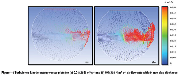
Mixing time was found to decrease with increasing specific mixing power for the cases with thin simulated slag thickness. For a relatively thick simulated slag layer, the mixing time increased with an increase in the specific power of mixing; this is consistent with the results obtained by Valencia et al. (2004), who reported that an increase in air power generated more turbulence in the converter, with little benefit in terms of mixing quality in the mean flow of the bath. Figure 4 shows turbulence kinetic energy vector plots obtained in our study for air flow rates of 0.01125 N m3 s-1 and 0.01375 N m3 s-1at constant slag thickness of 54 mm. It is evident from Figure 4(b) that at high blowing rates, high turbulence is created and concentrated in the tuyere region, as compared to low blowing rates shown in Figure 4(a). This phenomenon results in longer mixing times for the high slag thickness, but slightly shorter mixing times for low slag thickness, as shown in Figure 5.
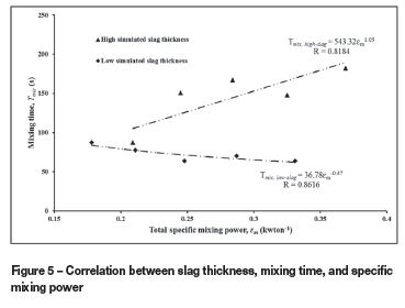
From the results of the physical experiments, mixing time in terms of total specific mixing power (buoyancy plus gas kinetic energy) was analysed for 27 mm and 108 mm simulated slag thicknesses representing low slag and high slag operations respectively (Figure 5). The shorter mixing times obtained for low slag thickness and longer mixing times for higher slag thickness are attributed to the generation of increased turbulence in the converter, with little benefit in terms of mixing quality in the mean flow of the bath liquid.
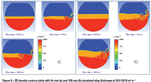
Numerical simulations revealed that with thin simulated slag thicknesses, the slag is pushed to the opposite side of the tuyere line with the plume region being composed of almost only matte, as shown in Figure 6(a). This increases hydrodynamic pressure to the rising bubbles and hence increases the specific energy dissipated to the liquid phase for bath recirculation. This is due to high bubble retention in the liquid, which in turn increases mixing efficiency. However, the benefits of such retention time are offset by the effects of phase interaction, friction, and diffusion, which dissipate a substantial amount of energy at high slag volumes. The mechanism of momentum transfer at simulated matte (simulated) slag-air interfaces fritters away potential recirculation energy. At an increased simulated slag thickness of 108 mm, as can be seen in Figure 6(b), the effect of interaction and dispersion is highly pronounced. As such, mixing in the simulated matte phase is expected to decrease. The effectiveness of the interphase exchange momentum is also reduced due to dissipation of energy by the simulated slag as a result of localized secondary recirculation flow, which is more pronounced at high simulated slag volumes. This observation is in agreement with the results reported by Han et al. (2001) on flow characteristics of a gas-stirred ladle model.
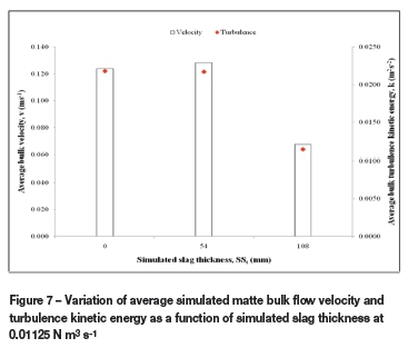
As indicated by Turkoglu and Farouk (1991), liquid bulk circulation rate is inversely proportional to mixing time, which indicates that the bulk motion of the liquid plays an important role in mixing, and hence that liquid recirculation rate can be used as a measure of mixing efficiency. Figure 7 shows the variation of average bulk velocity and turbulence kinetic energy with simulated slag thickness. Average bulk velocity and turbulent kinetic energy were calculated as the averages in infinite sampling points in the simulated matte calculation domain. It can be seen from Figure 7 that at 54 mm simulated slag thickness and above, the bulk recircu-lation velocity is greatly reduced. Moreover, turbulence was observed to decrease with increasing simulated slag height. Both these factors translate into increased mixing time.
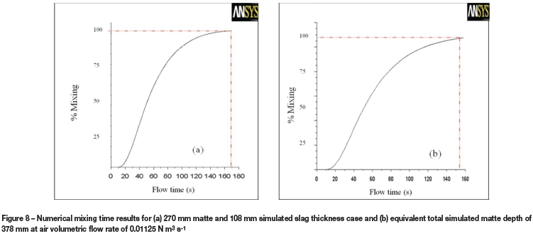
In an effort to understand whether increased mixing time in the multiphase system was due to phase interactions, mixing time numerical simulations were also conducted with equivalent heights of matte only and matte plus simulated slag, of which simulated slag was 108 mm. Numerical simulations with only simulated matte depth displayed improved mixing efficiency, as shown in Figure 8, where mixing time is seen to decrease from 168 seconds (with slag) to 153 seconds (no slag). This could be attributed to improved momentum transfer between gas bubbles and the bulk liquid due to a high gas retention time, as well as the absence of energy dissipation in recirculation flow, and hence increased mixing efficiencies.
It is possible to postulate that when the melt height in the PSC is generally low, the gas channels though the melt along the vertical sidewall of the tuyere injection nozzle axis. In that case, the residence time of the gas bubbles in the melt is reduced, which in turn will reduce gas-melt interactions within the bulk melt. Therefore, as a result of channelling, the effectiveness of the gas momentum and power transfer to the bulk liquid flow is reduced. This adversely affects the mixing, liquid-liquid, and liquid-solid mass transfer within the bath. On the other hand, with an increase in liquid height in the converter, the axial plume residence time increases, which results in improved interaction between the gas and liquid. This will lead to more matte entrainment into the rising plume and a stronger agitation in the bath. In order to maintain consistent mixing power and offset the adverse conditions due to increased volumes of rising liquids, the bath height with respect to matte and slag ratio should be monitored in order to make necessary adjustments to the gas blowing rates for energy-efficient processing.
Solid-liquid mass transfer
Pyrometallurgical processes are multiphase in nature, involving gas-liquid-solid interactions. In PSC operation, the addition of cold solids to the liquid matte in the form of fluxing agents (silica sands) for slag liquidity and process scrap and reverts for temperature control is a common practice. It is reasonable to propose that with such practice, the solid-liquid mass transfer step may play an important role in the performance of the process and attainment of liquid bath homogeneity. In this work, solid additions were simulated with sintered benzoic acid compacts spatially positioned in the model converter. Water and kerosene were used to simulate matte and slag respectively. Solid-liquid mass transfer was characterized by experimentally determined mass transfer coefficient values for benzoic acid sintered compacts and calculated dimensionless turbulence characteristic values. Two simulated slag thickness, 54 mm and 108 mm, were used in the experiments, representing 20% and 40% of simulated matte height respectively. These two simulated slag volumes will be referred to as 'low' and 'high' simulated slag.
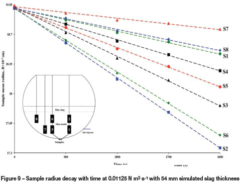
The experimental results revealed that the dissolution varied with respect to all air flow rates and simulated slag volumes considered in this study. In Figure 9, S2 lies in the same location as S3 with respect to tuyere position but close to the simulated slag-matte interface. The dissolution rate was higher at S2 than at S3. On the other hand, sample S6, which is also near the simulated slag-matte interface, exhibited the second-highest dissolution rate ahead of S5. These observations indicate that there exists a circulatory and stratified flow regime in which the velocity flow variable differs with respect to the depth of the samples in the simulated liquids. This observation is consistent with earlier work by Vaarno et al., (1998), who measured experimentally and numerically liquid velocity distributions in a water model of a PSC. Their study identified a circulatory flow field in the converter with higher velocities near the bath surface. In the current work, this phenomenon is further attested to by the behaviour of S7 and S8, with S8 experiencing higher dissolution rates than S7. S1 and S4 also confirmed flow stratification, with higher dissolution being experienced at S4, which is near the slag-matte interface. It is also instructive to notice that both S1 and S4 had lower dissolution rates compared to S2, S3, S5, and S6. This observation serves to highlight that S1 and S4 are positioned in dead zones near the converter sidewalls in the model.
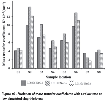
Two trends of dissolution behaviour were observed in terms of K values as a function of simulated slag thickness and air flow rate. With low slag thickness, as air flow rate increased from 0.00875 N m3s-1to 0.01122 N m3s-1, K increased, then decreased towards 0.01375 N m3 s-1 but still remained higher than at 0.00875 N m3 s-1, as shown in Figure 10. This is possibly due to an increase in the fragmented body forces between the sample and emulsion, which increases the transport process as air flow rate increases. However, the observed decrease in mass transfer values as the air flow is increased further to 0.01375 N m3 s-1 is possibly due to shallow submergence of the tuyeres, with channelling phenomena becoming prevalent at high air flow rates (Adjei and Richards, 1991). Channelling will cause a breakdown of energy transfer to the system, hence a reduction in the transport process which results in the observed decrease in transport variable.
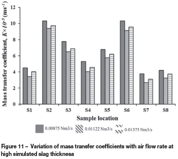
With high simulated slag thicknesses, and hence high slag volumes (Figure 11), we observed a decrease in values of K as air flow was increased from 0.00875 N m3 s-1 to 0.01122 N m3s-1. It is possible that at these high slag volumes, phase interactions and interphase friction are strongly pronounced - so much so that fragmented body forces between the sample and emulsion are weakened, thereby retarding the transport process. A noticeable increase in the mass transfer parameters was observed with an increase in air flow to 0.01375 N m3s-1. This could be a result of increased energy input to the system, the situation being sustained by slightly deeper tuyere submergence caused by the high slag volume, which allows for effective exchange of momentum between air and liquid. With the above facts in mind, it should be noted that the mass transfer values are still lower than those at 0.01122 N m3s-1with a low slag thickness (Figure 10). This scenario depicts under utilization of capacity in terms of energy at high simulated slag volumes.
Phase dispersion
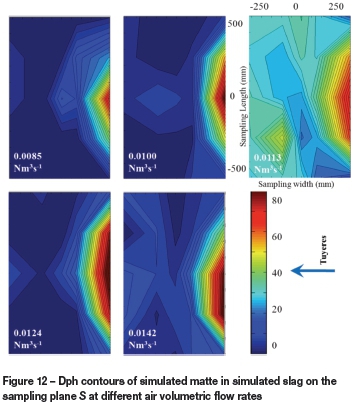
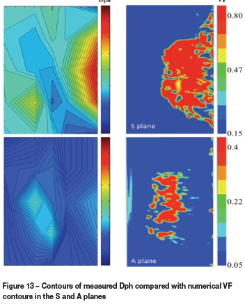
Experimentally measured dispersed phase holdup (Dph) at different planes in the water bath (Figure 12) was verified numerically with contours of volume fraction (VF) of simulated matte in simulated slag and simulated slag in simulated matte phase in the S and A planes respectively at 0.0113 N m3s-1(Figure 13). The results revealed that the amount of dispersed simulated matte in simulated slag phase in the model increases with increasing air volumetric flow rate. Conversely, it has been observed that the average amount of dispersed simulated slag in matte decreases. This situation could be attributable to the effects of increased splashing in the converter as air volumetric flow rate increases. According to Koohi et al. (2008), the splashes in the PSC are mainly matte constituents as slag is pushed to the radial position (Figure 6) opposite the tuyere side, forming a plume of matte. Splashes will disperse the matte out of the converter and those with insufficient kinetic energy will fall back onto the slag in the bath, resulting in increased matte entrapment in the slag layer (Figure 13, S-plane).
Numerical analysis of combined top and lateral blowing
As discussed in the previous sections, typical current operation of lateral-blown PSCs results in the common phenomenon of splashing and slopping due to air injection. The splashing and wave motion in the converter causes metal losses and potential lost production time due to the necessity for intermittent cleaning of the converter mouth, and thus reduced process throughput. Against such background, the purpose of this section is to report simulation results of combined blowing in a PSC using CFD and to compare the results of mixing propagation, turbulent kinetic energy, and splashing with the conventional common practice. This was done by creating four different sliced PSC models. The first two models represent the conventional practice, with tuyeres located at a lateral position on the converter. The slag layer thickness will be different for these two models, representing low and high slag volumes. The other two models also have dissimilar slag layer heights, but in these cases air will be injected from a combined top and lateral position. Understanding the effect of combined top and lateral blowing could help identify whether combined top and lateral blowing is feasible for industrial usage, and possibly lead to alternative technologies for increased process efficiency in industrial PSCs.
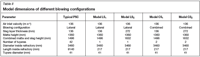
In this work, 2D and 3D simulations were carried out based on slice models of a typical industrial copper PSC. Due to the mesh densities involved in these simulations, simulation of the entire converter was not feasible. Table II gives the dimensions, parameters for tuyere configurations, and bath (matte and slag) heights of the four different slice models based on the typical industrial converter considered in this study. LS1, LS2, CS1, and CS2 refer to lateral (L) blowing and combined (C) blowing models with low slag thickness (S1) and high slag thickness (S2) respectively. The dimensions and blowing parameters used correspond to those commonly employed in industry for lateral-blown PSCs. The velocity of the top-blowing air was taken to be the same as that for the lateral-injected air, as the aim of the study is to observe the effects of different locations of blowing and variance in slag layer height, and not the effects of inlet velocity.
The position of the top-blown lance above the molten liquids in the converter is very important. In the present investigation, the height and alignment of the top-blowing lance were selected after considering different sources in the literature regarding the position of lances for molten baths. For instance, Marcuson et al. (1993) mentioned that the lance was susceptible to degradation and recommend a lance height of 400 mm above the molten bath to ensure a high gas velocity at impact. In this study, the top-blowing lance was positioned 500 mm above the matte.
The flow conservation governing equations, the VOF equation, and turbulence model equations were solved with FLUENT version 14.0. A Semi-Implicit Method for Pressure-Linked Equation (SIMPLE) algorithm was used for pressure-velocity coupling. A Compressive Interface Capturing Scheme for Arbitrary Meshes (CICSAM) discretization method was used to obtain face fluxes, with a piecewise-linear approach. This scheme was necessary due to the high viscosity ratios involved in this flow problem (ANSYS, 2011). A time step of 0.0001 seconds was used and was found to be sufficient for maintenance of numerical convergence and stability at every time step. Convergence of the numerical solution was determined based on surface monitoring of integrated quantities of bulk flow velocity, turbulence, and scaled residuals of continuity such as the x-, y-, z-velocity components, k, and ε. The residuals of all quantities were set to 1x10⁻³ and the solution was considered converged when all the residuals were less than or equal to the set value.
The solutions for the numerical simulations, based on density contour distribution of the liquids, are given in Figure 14 for the four models developed. In the analysis of these isosurfaces created in the middle of the models normal to the z-direction, it can qualitatively be observed that spitting and splashing originate from the tuyere side of the converter in all cases. This is due to the rupture of large bubbles generated from the tuyeres as they exit the liquid bath at the liquid surface. In the process, stable waves are created with slag being pushed to the sidewalls opposite the tuyere, leaving a plume generally consisting of matte phase.
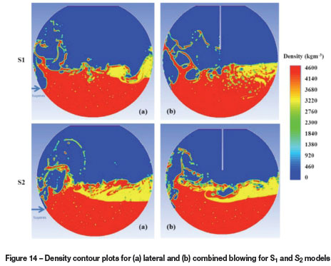
It was also observed that there is an increase in matte velocity with combined blowing at high slag conditions, indicating the critical influence of lance height for combined blowing. In contrast, at high slag volume (272 mm slag thickness), it can be observed in Figure 14(b) that the air from the top lance has a pronounced effect on the wave path, creating a vortex on impact with the bath surface. In this instance, the distance from tuyere tip to bath surface is approximately 364 mm. This observation is consistent with the recommendation by Marcuson et al. (1993) for optimal lance tip to bath surface distance.
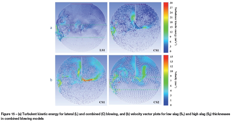
Turbulence kinetic energy distribution in gas-stirred systems is one of the important parameters influencing the mixing efficiency. It can be seen from Figure 15(a) that the addition of top-lance blowing increases the turbulence kinetic energy in the converter free space above the liquid. In the liquid bath, turbulence kinetic energy remains relatively the same, and thus we expect a similar overall oxidation rate in the two systems under consideration. However, it could be reasoned that the increased turbulence kinetic energy in the converter free space could speed up the fall of splash droplets back to the liquid bath surface. To further illustrate the effect of slag thickness, and thus the importance of tuyere tip-bath surface distance, velocity vector plots for 136 mm (S1) and 272 mm (S2) slag thickness are shown in Figure 15(b). It is evident that the average bulk velocity is high in the case of low slag thickness, especially in the air free space due to underdeveloped impact of the air as a result of high tuyere tip to bath surface distance.
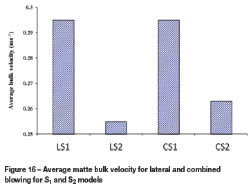
This phenomenon can be further illustrated by comparing the average bulk velocity in the converter for all four models. Figure 16 illustrates the average matte bulk velocity profiles for lateral and combined blowing. Through observation one could infer that there is an increase in matte velocity with increased slag height, thus indicating the critical aspect of lance height for combined blowing. This is in contrast to low slag height models, which show almost equal matte velocities due to the ineffectiveness of jet penetration at a high lance height.
Implications for combined top and lateral blowing on industrial-scale converters
PSC conversion is a batch operation and meticulous control of slag and matte volumes is currently not possible. However, in previous studies (Han et al., 2001) it has been observed that high slag volumes dissipate substantial amounts of energy that would otherwise be used for recirculation and improved bath mixing. From this study, it is quite evident that there is an incentive for combined blowing as it provides energy that improves recirculation of the liquid bath. The bath to lance tip height, which affects the amount of impact energy to the bath as previous reported by Marcuson et al. (1993), is critical to the operation of combined blowing.
Conclusions
In this study, the influence of a simulated slag layer on mixing and phase dispersion characteristics and behaviour in an industrial Peirce-Smith converter (PSC) was studied experimentally, using a 0.2-scale water model, and numerically by means of 2D and 3D simulations. The results from numerical simulation with volume of fluid (VOF) and realizable turbulence model were found to be in good agreement with the experimental results. The experimental and numerical analysis results of phase distribution were in fair agreement. There appears to be a critical simulated slag thickness in the PSC model, above which increasing air flow rate results in extended mixing times due to a combination of channelling and secondary recirculation in the slag layer. Secondary recirculation results in dissipation of energy, leading to a reduction in the bulk fluid recirculation velocity and turbulence kinetic energy. An increased matte fraction in slag and matte systems increases mixing efficiencies, possibly due to high bubble retention. It has been shown that the slag layer, as well as air flow rates, has an influence on the bulk recirculation velocity and turbulence, thus affecting the mixing efficiency in the PSC. The dispersion of simulated matte in simulated slag has been found to increase with increasing air volumetric flow rate, whereas the dispersion of simulated slag in simulated matte decreases. The difference is thought to be due to the complex interaction of phases in terms of precipitation mechanisms, coagulation, and flotation, as well as fluid motion, in the converter. The experimental results were in good agreement with the numerical simulation results in the domain of the experimental set-up.
Solid-liquid mass transfer phenomena were also investigated experimentally using the cold model with the objective of spatial mapping the converter regions. The flow pattern in PSCs was found to be stratified, with high bath velocities near the bath surface. Both air flow rate and slag quantities affect dissolution behaviour in slag-matte systems. The solid-liquid mass transfer rates can be effectively controlled by close monitoring of slag quantities and air flow rates. Dead zones associated with poor dissolution rates were observed close to the sidewalls of the converter.
As a potential process alternative to prevent metal/matte losses due to splashing and wave motion in the converters, and hence to increase process efficiency, we studied combined blowing configuration in an industrial PSC with a top lance and lateral nozzles by using the 3D numerical simulations. The results revealed that wave formation and splashing can be reduced by employing combined blowing. Qualitative analysis of density contour plots suggests that combined blowing will most likely result in increased process efficiency as the energy of the top-lance injected air is utilized in reacting with new surfaces and increasing the static pressure in the system, thereby decreasing the amplitude of standing waves and thus increasing mixing efficiency, and hence the process efficiency, in the bulk liquid bath. The study also clearly demonstrated that combined blowing increases turbulence in the bath, and is thus likely to increase process throughput. A quantitative comparison of the average bulk flow liquid velocity demonstrated that simulated slag layer thickness has a great effect on the bulk recirculation velocity, as it influences the utilization of energy from the top-blown lance, thus increasing mixing efficiency. The optimal position for the lance above the liquid bath is thus critical. As the bath height varies during the blowing cycle, it might be necessary to meticulously vary the lance height during the blowing cycle to maintain a critical height.
Acknowledgements
The financial support received from NRF/THRIP funding is greatly appreciated. The authors also extend their thanks to the technical staff in the Stellenbosch University Process Engineering workshop.
References
Adjei, E. and Richards, G.G. 1991. Physical modelling of mass transfer in a Peirce-Smith converter. Copper 91-(Cobre 91), Ottawa, Canada, August, 1991. Vol. IV. pp. 377-388. [ Links ]
ANSYS, I. 2011. ANSYS FLUENT Theory Guide. Release 14.0. Ansys Inc., Canonsburg PA. [ Links ]
Castillejos, A.H. and Brimacombe, J.K. 1987. Measurement of physical characteristics of bubbles in gas-liquid plumes: Part II. Local properties of turbulent air-water plumes in vertically injected jets. Metallurgical and Materials Transactions B, vol. 18, no. 4. pp. 659-671. [ Links ]
Gonzalez, J., Real, C., Palomar-Pardave, M., Hoyos, L., Gutierrez, M., and MIRANDA, R. 2008. CFD simulation gas-liquid flow in a copper converter with bottom air injection. International Journal of Chemical Reactor Engineering, vol. 6, no. 6. pp. 1-22. [ Links ]
Gray, N.B., Nilmani, M., and Fountain, C.R. 1984. Investigation and modelling of gas injection and mixing in molten liquid processes. AusIMM Melbourne Branch, Symposium on Extractive Metallurgy. pp. 269-277. [ Links ]
Han, J.W., Heo, S.H., Kam, D.H., You, B.D., Pak, J.J., and Song, H.S. 2001. Transient fluid flow phenomena in a gas stirred liquid bath with top oil layer - approach by numerical simulation and water model experiments. ISIJ International, vol. 41, no. 10. pp. 1165-1172. [ Links ]
Haida, O. and Brimacombe, J.K. 1985. Physical-model study of the effect of gas kinetic energy in injection refining processes. Transactions of the Iron and Steel Institute of Japan, vol. 25, no. 1. pp. 14-20. [ Links ]
Hoefele, E.O. and Brimacombe, J.K. 1979. Flow regimes in submerged gas injection. Metallurgical and Materials Transactions B, vol. 10, no. 4. pp. 631-648. [ Links ]
Kim, S.H. and Fruehan, R.J. 1987. Physical modeling of liquid/liquid mass transfer in gas stirred ladles. Metallurgical and Materials Transactions B, vol. 18, no. 2. pp. 381-390. [ Links ]
Koohi, A.H.L., Halali, M., Askari, M., and Manzari, M.T. 2008. Investigation and modeling of splashing in the Peirce Smith converter. Chemical Product and Process Modeling, vol. 3, no. 1. Article 2. [ Links ]
Kyllo, A.K. and Richards, G.G. 1998a. A kinetic model of Pierce Smith converter: Part I. Model formulation and validation. Metallurgical Transactions B, vol. 29B. pp. 239-250. [ Links ]
Kyllo, A.K. and Richards, G.G. 1998b. A kinetic model of Pierce Smith converter: Part II. Model application and discussion. Metallurgical Transactions B, vol. 29B. pp. 251-259. [ Links ]
Liow, J.L. and Gray, N.B. 1990. Slopping resulting from gas injection in a Pierce-Smith converter: water model. Metallurgical and Materials Transactions B, vol. 21, no. 6. pp. 987-996. [ Links ]
Marcuson, S.W., Landolt, C.A., Amson, J.H., and Davies, H. 1993. Converter and method for top blowing nonferrous metal. US Patent 5180423. [ Links ]
Mazumdar, D. 1990. Dynamic similarity considerations in gas-stirred ladle systems, Metallurgical and Materials Transactions B, vol. 21, no. 5. pp. 925-928. [ Links ]
Moreno, A., Sánchez, G., Warczok, A., and Riveros, G. 1998. Development of slag cleaning process and operation of electric furnace in Las Ventanas Smelter. Copper2003-Cobre 2003, vol. IV, book 1. Pyrometallurgy of Copper. Díaz, C., Kapusta, J., and Newman, C. (eds). CIM, Montreal. pp. 1-17. [ Links ]
Ramirez-Argaez, M.A. 2008. Numerical simulation of fluid flow and mixing in gas-stirred ladles. Materials and Manufacturing Processes, vol. 23, no. 1. pp. 59-68. [ Links ]
Real, C., Hoyos, L., Cervantes, F., Miranda, R., Palomar-Pardave, M., Barron, M., and Gonzalez, J. 2007. Fluid characterization of copper converters. Mecánica Computational, vol. 26. pp. 1311-1323. [ Links ]
Rosales, M., Fuentes, R., Ruz, P., and Godoy, J. 1999. A fluid dynamic simulation of a Teniente Converter. Copper 99- Cobre 99, Phoenix, Arizona. pp. 107-121. [ Links ]
Rosales, M., Valencia, A., and Fuentes, R. 2009. A methodology for controlling slopping in copper converters by using lateral and bottom gas injection. International Journal of Chemical Reactor Engineering, vol. 7, no. 1. pp. 1868. [ Links ]
Sahai, Y. and Guthrie, R.I.L, 1982. Hydrodynamics of gas stirred melts: Part I. Gas/liquid coupling. Metallurgical and Materials Transactions B, vol. 13, no. 2. pp. 193-202. [ Links ]
Schwarz, M.P. 1996. Simulation of gas injection into liquid melts. Applied Mathematical Modelling, vol. 20, no. 1. pp. 41-51. [ Links ]
Sinha, U.P. and McNallan, M.J. 1985. Mixing in ladles by vertical injection of gas and gas-particle jets-A water model study. Metallurgical and Materials Transactions B, vol. 16, no. 4. pp. 850-853. [ Links ]
Stapurewicz, T. and Themelis, N.J. 1987. Mixing and mass Transfer Phenomena in Bottom-Injected Gas--Liquid Reactors. Canadian Metallurgical Quarterly, vol. 26, no. 2. pp. 123-128. [ Links ]
Turkoglu, H. and Farouk, B. 1991. Mixing time and liquid circulation rate in steelmaking ladles with vertical gas injection. ISIJ International, vol. 31, no. 12. pp. 1371-1380. [ Links ]
Vaarno, J., Pitkala, J., Ahokainen, T., and Jokilaakso, A. 1998. Modelling gas injection of a Peirce-Smith-converter. Applied Mathematical Modelling, vol. 22, no. 11. pp. 907-920. [ Links ]
Valencia, A., Cordova, M., and Ortega, J., 2002. Numerical simulation of gas bubbles formation at a submerged orifice in a liquid. International Communications in Heat and Mass Transfer, vol. 29, no. 6. pp. 821-830. [ Links ]
Valencia, A., Paredes, R., Rosales, M., Godoy, E., and Ortega, J. 2004. Fluid dynamics of submerged gas injection into liquid in a model of copper converter. International Communications in Heat and Mass Transfer, vol. 31, no. 1. pp. 21-30. [ Links ]
Valencia, A., Rosales, M., Paredes, R., Leon, C., and Moyano, A. 2006. Numerical and experimental investigation of the fluid dynamics in a Teniente type copper converter. International Communications in Heat and Mass Transfer, vol. 33, no. 3. pp. 302-310. [ Links ]
Warczok, A., Riveros, G., and Montenegro, V. 2004. Utilization of magneto hydrodynamics phenomena in slag cleaning. Copper-Cobre 2003 International Conference. Vol. IV: Pyrometallurgy of Copper. Book 2: Copper Sulfide Smelting Technology Development, Process Modeling and Fundamentals. The Metallurgical Society of CIM, Montreal. pp. 61-78. [ Links ]
© The Southern African Institute of Mining and Metallurgy, 2015. ISSN2225-6253. This paper was first presented at the, Pyrometallurgical Modelling Principles and Practices, 4-5 August 2014, Emperors Palace Hotel Casino Convention Resort, Johannesburg.

