


Servicios Personalizados
Articulo
 Inglés (pdf)
 Articulo en XML
 Referencias del artículo
Indicadores

Links relacionados
-
 Citado por Google
 -
 Similares en Google
Compartir

 Permalink
Journal of the Southern African Institute of Mining and Metallurgy
versión On-line ISSN 2411-9717
versión impresa ISSN 2225-6253
J. S. Afr. Inst. Min. Metall. vol.115 no.5 Johannesburg may. 2015
PYROMETALLURGICAL PAPERS
Physical and numerical modelling of a four-strand steelmaking tundish using flow analysis of different configurations
J.H. Cloete; G. Akdogan; S.M. Bradshaw; D.K. Chibwe
Process Engineering Department, University of Stellenbosch
SYNOPSIS
Modern tundishes have evolved as vessels to serve as the final step in refining of molten steel by removing inclusions and promoting thermo-chemical homogeneity. In this study the flow behaviour in a four-strand tundish was investigated by means of a ½-scale water model as well as numerical modelling. The numerical and physical models were used to characterize residence time distribution and calculate properties pertaining to tundish flow regime. Three different tundish configurations were investigated: a bare tundish with no flow control devices, a tundish with a turbulence inhibitor, and a tundish with both a turbulence inhibitor and a dam. The physical and numerical models showed that a tundish without flow control devices is prone to significant short-circuiting. A tundish with a turbulence inhibitor was shown to be successful in preventing short-circuiting and provided surface-directed flow that might assist the removal of inclusions from the melt. However, it was also observed that the upward-directed flow caused the maximum turbulence kinetic energy near the surface to increase dramatically. The potential for slag entrainment should therefore be considered during the design and operation of tundishes with turbulence inhibitors.
Keywords: tundish, steelmaking, CFD, physical modelling, numerical modelling
Introduction
The metallurgical importance of tundishes has led to much research into various aspects of tundish operation and design, and investigations of the flow properties and inclusion behaviour through both physical and numerical modelling. A large portion of the research has been focused on the use of flow control devices to alter flow patterns and improve the tundish performance by eliminating short-circuiting, increasing the residence time to promote inclusion removal, and reducing variation between strands in multi-strand tundishes (Craig et al., 2001, 2003; Kumar et al., 2007, 2008; Jha et al., 2008; Tripathi and Ajmani, 2011; Zhong et al., 2007). Craig et al. (2001) worked on the optimization of a single-strand stainless steel caster tundish for two separate tundish configurations - dam and weir, and baffle with angled holes and an impact pad. Significant improvements of up to 34% in minimum residence time were obtained for the second configuration. Moreover, in 2003 Craig et al.
reported a CFD study combined with mathematical optimization to design the configuration of the new enlarged tundish. Design variables chosen included the position and sizes of baffles and baffle holes and pouring box width, while the design objective was maximization of the minimum residence time (MRT) at operating level and at a typical transition level. The study showed that mathematical optimization techniques can be coupled with CFD techniques to obtain optimum tundish designs with significant improvements.
In general, most authors have assumed the tundish to be isothermal, but some have looked at the effect of temperature gradients due to heat loss from the tundish (Liu et al., 2008; Mishra et al. 2012; Miki and Thomas, 1999) or the effect of the cooling rate of melt arriving from the ladle (Qu et al., 2012). Modelling strategies are necessary when investigating tundish behaviour because of the high temperature and opaque nature of the steelmaking process, which makes performing certain experiments on the real system impossible. For the physical modelling procedure, full- or reduced-scale water models, based on Reynolds number or Froude number similarity, are used (Mazumdar and Guthrie, 1999). The flow behaviour is usually characterized by investigating the residence time distribution (RTD) curves under various operating and design parameters.
In this study a physical model was used to investigate the effect of different turbulence inhibitor designs on the flow properties of a four-strand trough-shaped tundish to contribute to the current knowledge and understanding of multi-strand tundish design and operation. Of specific interest is a design proposed by Kumar et al. (2008) where the use of a turbulence inhibitor with holes in combination with low dams is proposed to improve flow properties. This study investigated whether the addition of the holes and dams provides significant advantage compared with using only a turbulence inhibitor without holes, which would be less expensive to construct and maintain. A numerical model was also developed in FLUENT to simulate the flow behaviour in the water model, improving the understanding of the results of the physical model experiments. The effect of the assumptions of symmetry and dynamically steady flow on numerical results, which were frequently used in tundish CFD studies to reduce the computational time (Kumar etal., 2008; Tripathi and Ajmani, 2011; Zhong et al., 2007; Mishra et al., 2012; Tripathi and Ajmani, 2005; Jha et al., 2001) was also investigated. This is of importance, as there is no information on the effects of these assumptions on computational accuracy in the available literature on tundishes. The numerical model was also used to investigate the effect of the upward flow on surface turbulence, since high surface turbulence creates the potential for slag entrainment, which will cause new inclusions to form and lower the product quality. This is therefore a factor worth considering when implementing the use of turbulence inhibitors.
Experimental modelling
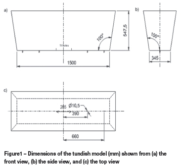
The physical model was constructed from clear, 6 mm PVC, with all dimensions scaled to a 1:2 ratio compared to the industrial tundish. The four sidewalls were inclined by 10°. The dimensions of the tundish are shown in Figure 1.
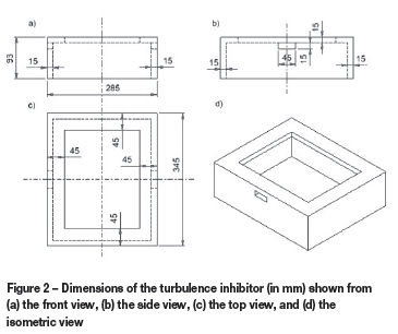
The turbulence inhibitor was constructed from grey PVC, 15 mm thick. The dimensions are shown in Figure 2. The turbulence inhibitor was attached to the tank using silicone adhesive, when required for experiments. The holes in the side of the turbulence inhibitor could be closed by inserting correctly sized PVC blocks into them and sealing the gaps with silicone.
The complete physical model set-up is shown in Figure 3.
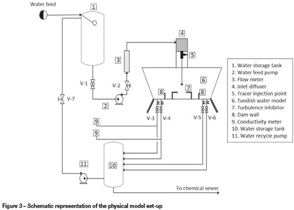
To simplify construction, the water feed tank was placed to the side of the tundish model. However, CFD simulations showed that by simply placing a 90° bend in the feed pipe above the tundish, an asymmetric velocity profile would develop. To rectify this, an 8 litre cubic tank, made from stainless steel, was suspended above the inlet point at the centre of the tundish. CFD simulations showed that this ensures an even velocity profile in the inlet pipe. The inlet pipe had a diameter of 30 mm and penetrated the tundish to 165 mm from the bottom of the tundish. A T-junction at the top of the inlet pipe allowed tracer fluid to be injected into the inlet stream using a syringe. Outlet holes were drilled in the bottom of the bath. The desired flow rate, at the bath height used, was obtained by calculating the required diameter of the outlet from Bernoulli's equation. A PVC insert with the correct diameter was then placed into each of the holes. The measured flow rates in each of the outlets were within 2% of the desired rate. Apart from geometric similarity, the Froude number was used as the criterion for dynamic similarity. In reduced-scale water modelling it is impossible to simultaneously achieve both Froude number and Reynolds number similarity. It has been shown by Sahai and Emi (1996) that the RTD response of tundish water models is insensitive to the Froude number over a large range of values, and to the Reynolds number, if the tundish is operated in the turbulent regime. Since tundishes are generally operated turbulently, either Froude number or Reynolds number similarity may be used to scale the flow rates for the water model. However, Froude number (Equation 1) similarity is required for the modelling of inclusions and is therefore most often used in tundish physical modelling. In this study, Froude number similarity was selected to enable addition of inclusions to the water model in the future.
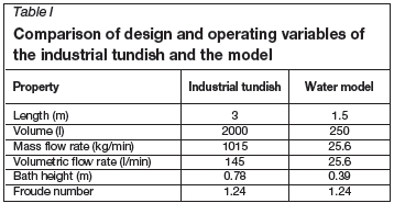
Table I gives a comparison of design and operating parameters for the industrial tundish and the 1:2 water models. During scaling based on the Froude number, the inlet flow rate of the water model was calculated so that the Froude number at the inlet is identical to that of the industrial tundish. The Froude number at the inlet is calculated as:
During the experiments, the water was first allowed to run for approximately 15 minutes at the desired flow rate to allow a steady flow to develop in the tundish model. An aqueous potassium chloride solution (200 g/l) was used as tracer. To initialize the experiment 50 ml of the tracer solution was injected near the inlet. This was done over a period of five seconds to prevent the tracer injection from disturbing the inlet velocity profile to a significant extent. The delay this caused was justified by the fact that for all set-ups, except for the bare tundish, the minimum residence times are relatively large compared to this delay.
For the duration of the experiment the total dissolved solids in the water passing through an outlet was monitored using a conductivity meter. The conductivity meter was placed in a small container below the outlet to prevent disturbance of the flow pattern within the tundish. The volume of the container was minimized to allow the delay caused by the mixing to be small compared to the residence times observed. The experiment was performed for only two of the outlets, because of the symmetry of the geometry. Five experiments were performed for each tundish configuration to obtain an average residence time distribution that accounts for variation between runs.
Flow characterization
Several properties were calculated from the RTD results of both the physical and numerical experiments to characterize the flow in the tundish being studied. The first step was to derive the dimensionless C-curve for the tundish. The dimensionless time, θ, was calculated as:

where t is the theoretical mean residence time,

The dimensionless concentration of strand i (the outflow at outlet i) can be calculated as:
where V is the total volume of the tundish, ci the concentration in the strand, and M the total amount of tracer injected.
Since the flow rates in all strands are equal, the overall dimensionless concentration can be simply calculated as the average of the individual strand concentrations. Another important characteristic property of the flow is the mean residence time, tmean, calculated as:
To calculate the mean residence time for an individual strand, the average concentration at the outlets, C, is simply substituted by the concentration at the strand being considered. The tundish performance can further be classified by dividing the tundish into three flow volumes: the plug volume ( Vp), the well-mixed volume ( Vm), and the dead volume (Vd), which are defined according to the modified combined model by Ahuja and Sahai (1986) as:
The ratio Qa/Q is the fractional volumetric flow rate through the active region and is equal to the area under the C-curve between the bounds of θ = 0 and θ = 2. After θ = 2, the tail data is considered to be only from the dead regions.
Numerical modelling
Numerical simulation has several advantages over physical modelling. Firstly, it provides information on properties throughout the flow domain. Therefore, information regarding the velocity and turbulence kinetic energy profiles can be used to explain the RTD results obtained through physical modelling and to identify possible ways to improve the system. Secondly, once an accurate model has been developed, different geometries can easily be studied using the numerical model without making costly and time-consuming changes to a physical model. In this study the commercial CFD package FLUENT® 14.5 was used.
A review of the literature on tundish numerical modelling (Chattopadhyay et al., 2010) showed that the majority of authors had used the standard k-ε model to model turbulence. The standard k-ε turbulence model has been shown to be reasonably accurate in predicting flow characteristics for a single-strand tundish from RTD experiments, and is still preferred above slightly more accurate models because of significantly lower computational times (Jha et al., 2003). For this study the realizable k-ε (RKE) model was selected since it provides additional accuracy for swirling flows and is only slightly more computationally expensive than the standard k-ε model.
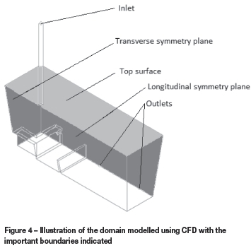
At the inlet, the normal velocity, calculated from the inlet area and the volumetric flow rate, was specified, assuming a flat profile at the ladle outlet. The top surface of the model was assumed to be flat and frictionless. This was done by declaring the surface as a wall with zero shear stress components in all three dimensions. The outlets were specified as pressure outlets with zero gauge pressure. The combination of the bath height and outlet diameter caused the total outlet mass flow to be equal to the inlet mass flow rate. All other surfaces were set to stationary walls, assuming the no-slip condition. The standard wall function was used to model the turbulence near the walls. The flow was assumed to be symmetrical over the planes through the centre of the bath along its length and its width, hence a quarter model was used. Therefore, zero gradients of all properties were assumed normal to these planes. The three-dimensional geometry of the fluid volume was created for the different geometries considered in this study and meshed using a tetrahedral mesh. The mesh was refined near curved walls and walls with close proximity to each other to produce a mesh of acceptable quality. Figure 4 shows the domain modelled with CFD.
In FLUENT, the flow and turbulence in the domain was first solved for steady flow, reaching a converged solution after approximately 12 000 iterations. For the final simulations, this initial solution was then used to locally refine the mesh in areas with high velocity gradients, using the gradient adaption function in FLUENT to obtain a more accurate solution. Throughout this study the minimum mesh orthogonal quality, a measure of the mesh quality, was maintained above 0.09 after gradient adaption. General guidelines suggest not using meshes with a minimum orthogonal quality of less than 0.05 (ANSYS, 2011); therefore sufficient mesh quality is maintained in this study. The final meshes contained approximately 2.8 million cells. The refined mesh was then used to solve for more accurate flow and turbulence solutions, requiring approximately 15 000 additional iterations for a converged solution. The transient and species solvers were then activated and the momentum and turbulence solvers turned off. This allowed the transient movement of the tracer fluid to be tracked in the steady velocity and turbulence fields. To simulate the physical experiment, the inlet boundary condition was set to add tracer to the tundish for five seconds, after which the addition of tracer was stopped. The concentration of tracer at the outlets was then monitored for two and a half times the theoretical mean residence time of the tundish to calculate the flow characteristic properties from the RTD response.
Grid independence and validation
A grid-independence study was performed to determine whether the mesh used is sufficient to accurately solve the flow in the tundish. This was done by repeating the numerical experiment for cases with different specified mesh sizes and comparing the RTD curves. A mesh specified with a constant size is preferred, since this is the easiest to set up and to use in different geometries. However, due to the contrast between the fast flow near the inlet and outlets and the very slow flow through the rest of the bath, the gradients in the bath will also vary to a large extent. For this reason, some areas will require a very fine mesh for accurate solutions, while most of the tundish will require only a coarse mesh. Therefore, by refining the mesh in regions with high velocity and turbulence gradients, a more efficient numerical model can be obtained. It was determined that grid independence was achieved by performing a single refinement, using the gradient adaption tool in FLUENT, on a 10 mm mesh, effectively reducing the size of the adapted cells to 5 mm. The velocity gradient at which adaption starts was determined by lowering the adaption threshold until the final solution no longer changed appreciably.
Results and discussion
In this study, aspects of the modelling procedure, such as symmetry, steady flow, and grid independence, were investigated. Next, the numerical model was validated against physical model results for three different configurations. The first set-up consisted of a bare tundish; therefore no flow control devices were used. The second set-up used a combination of the turbulence inhibitor with holes (TID), shown in Figure 2, and a low dam, which altered the flow by forcing it over the dam. The ratio of the dam height to the bath height was 0.2. The dam was placed at X=0.39L where X is the distance from the inlet to the dam and L is half the length of the tundish. The final set-up included a turbulence inhibitor, as shown in Figure 2, but with the side holes closed (TI). This allows the effect of the inclusion of the holes and dams, the design proposed by Kumar et al. (2008), to be evaluated. Finally, the numerical model results were used to evaluate the performance of the different tundish configurations.
Symmetry assumption
The geometry of the tundish used in this study is symmetrical over two planes. Using this knowledge, the fluid volume solved in FLUENT can be reduced to a quarter of its original size, reducing the computational time required significantly. Another simplification to the numerical model that is frequently used in tundish modelling is to assume dynamically steady flow. This assumption allows only the species equation, which converges much faster than the momentum and turbulence equations, to be solved transiently. This allows a single iteration per time step to be used, instead of approximately six to eight iterations per time step, drastically reducing the required computational time.
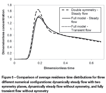
Although both of these assumptions are frequently used in tundish literature (Kumar et al., 2008; Tripathi and Ajmani, 2011; Zhong et al., 2007; Mishra et al., 2012; Tripathi and Ajmani, 2005; Jha et al., 2001), there is little information available about their effect on the numerical results. For this reason, the RTD curves were compared for three different cases: dynamically steady flow with two symmetry planes, dynamically steady flow without symmetry, and fully transient flow without symmetry. The tundish configuration used for the comparison was the turbulence inhibitor with holes in combination with the dams. However, because of the high computational requirements of the cases without simplifying assumptions, it was clear from preliminary grid-independence results that these solutions would not be feasible with the amount of cells required to reach grid independence. Hence a mesh of 14 mm cells was used for this comparative study to allow a rough estimate of the effect of these assumptions. The results shown use an average value of three simulations for each case, to account for variability in the results. The variability was much higher than for the final grid-independent runs. It was argued that this was because a new mesh was generated for each run, causing differing numerical errors due to the mesh being insufficiently fine in certain areas.
Figure 5 shows that the use of two symmetry planes does have an effect by slightly increasing the peak concentration. However, from knowledge gained from further grid investigations, it was seen that the effect of accurately resolving the mesh is much more important than solving the full geometry. Therefore, the use of the symmetry assumption is justified by the fact that it allowed the use of a finer mesh for a more accurate solution within acceptable computational time. It was therefore decided to use the model applying both symmetry planes and dynamically steady flow and focus on obtaining a more accurate grid-independent solution.
Flow characteristics
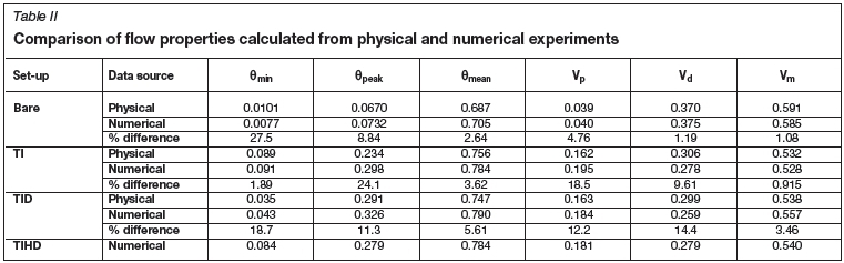
The characteristic flow quantities calculated from the physical and numerical experiments are summarized in Table II. Additionally, the RTD curves for the numerical solution for the three cases are shown in Figure 6.
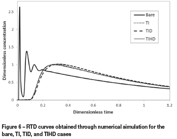
It is immediately apparent from the results that the introduction of the turbulence inhibitor offers advantages over the use of the bare tundish, as reported by Kumar et al. (2008). This is due to the fact that the turbulence inhibitor prevents short-circuiting along the bottom of the tundish by forcing upward flow. This leads to a significant increase in the minimum, peak, and mean residence times. Since sufficient time is necessary for the flotation of inclusions by buoyant forces to the slag, these increased residence times enable more inclusions to be absorbed by the slag layer. The result is that the number and size of non-metallic inclusions in the steel product will be reduced, providing a product of higher quality and value. Additionally, the higher plug flow volume fraction will provide less turbulent flow, which promotes the rising of the inclusions in the melt, while the decreased dead volume enhances thermal and chemical homogeneity in the product. Also, the upward-directed flow will help to bring the inclusions into contact with the slag for absorption. However, the primary purpose of this study was to evaluate the benefit of including holes and low dams to the turbulence inhibitor. The purpose of the holes is to accelerate upward flow away from the inlet region, thereby helping to eliminate dead volumes.
Comparing RTD results for the physical and numerical experiments using the adapted mesh in Table II, a good correlation was reached for the calculated flow characteristics. The average difference in the properties calculated for the three different configurations is approximately 10%. The largest difference, recorded for the breakthrough time in the bare model, is easily explained by the delays in input and measurement in the physical model, which become significant for the very short minimum time. The other value where large differences are detected is the peak time for the cases using a turbulence inhibitor. The numerical model predicts longer times for the peak concentration to be reached, which in turn translates into larger plug flow volumes and lower dead volumes. What is of importance is that despite these differences, general trends between the different configurations are the same for the physical and numerical model. The numerical model predicts the much lower breakthrough time due to short-circuiting in the bare set-up, as well as the small amount of short-circuiting for the case with the turbulence inhibitor with holes. Also, the bare tundish clearly has much lower plug flow and larger dead volumes than the configurations using turbulence inhibitors. It can therefore be concluded that the numerical model is acceptable for predicting the flow properties of different tundish configurations. This is particularly the case when considering the assumptions employed to reduce the computational time: symmetry, dynamically steady flow, and a flat, frictionless surface.
A numerical simulation was also performed for the case of a turbulence inhibitor with high dams (TIHD), where the height of the dams was increased by 50% over the TID case. Comparison of the flow characteristic properties in Table II shows that the higher dam is in fact able to prevent the short-circuiting in the system, since the value of the dimensionless minimum residence time increases from 0.043 to 0.084. Unfortunately, this improvement comes with a cost, as the peak residence time is significantly reduced and the dead volume is increased slightly. The likely reason for this deterioration of the flow quality is that the higher dam causes larger dead volumes between the turbulence inhibitor and the dams, as well as behind the dams.
It is observed that the minimum residence time for the TID case is less than half of that observed for the TI case. Therefore, a fraction of the flow will spend a very short time in the tundish, allowing larger inclusions to reach the outlet without being removed. In conclusion, it can therefore be stated that there does not appear to be any clear evidence that the use of holes and dams, in combination with a turbulence inhibitor, offers any significant benefit over using only the turbulence inhibitor.
The short minimum residence time for the TID case is most likely due to the dams being too low to completely eliminate short-circuiting of the flow passing through the holes. It was suggested that it might be possible to eliminate this problem by increasing the height of the dams. Industrial trials would be required to determine whether the prevention of large inclusions passing through by short-circuiting in the TID case is worth the reduction in peak residence time and increase in the dead volume when the height of the dams is increased. However, the TI case still performs better, without the added complication and cost of more complex flow control devices.
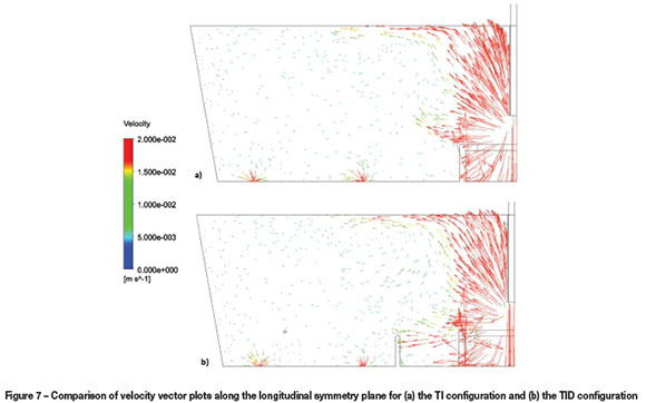
As a final matter of interest, the amount of turbulence predicted near the surface by the numerical model was investigated for the bare, TI, and TID cases. The magnitude of the turbulence near the tundish surface is very important due to the potential of slag entrainment. From previous discussions it is also obvious that the addition of the turbulence inhibitor influences the flow near the surface to a large extent by introducing upward flow in the inlet region. It is therefore necessary to evaluate the effect of the upward flow on surface turbulence, because entrainment due to increased turbulence may offset any benefits of longer residence times and increased plug flow gained by the addition of the turbulence inhibitor. It should be noted that without a separate study to determine the dependency of slag entrainment on turbulence conditions, the discussion regarding entrainment in this study is qualitative in nature. Nevertheless, the changes in flow along the longitudinal symmetry plane can be observed in Figure 7, and it can be seen that the upward-directed flow away from the inlet does increase. Comparing the turbulence kinetic energy values on a plane 2 cm below the surface of the tundish in Figure 8, it can be seen that the turbulence inhibitor changes the nature of the surface turbulence significantly. Firstly, it is noted that regions with slightly more turbulence develop at the far end from the inlet in all three configurations due to a circulation formed at the surface after flow is turned back at the back wall. However, this discussion will focus on the area near the inlet, where more surface turbulence occurs. In the bare tundish a high-turbulence region is formed near the sidewalls close to the inlet due to the flow rising along the walls. When the turbulence inhibitor is introduced, the high-turbulence region is centred on the inlet due to the rising flow from the turbulence inhibitor. It is important to note that the maximum value of turbulence (2.17x10⁻⁴m2/s2) is significantly increased from the bare case (9.67x10⁻⁵ m2/s2). It is therefore recommended that surface turbulence should be considered when changing the design of a tundish to include a turbulence inhibitor. It would be valuable to study whether the turbulence generated near the surface would be sufficient to entrain slag droplets, either by physical or numerical modelling.
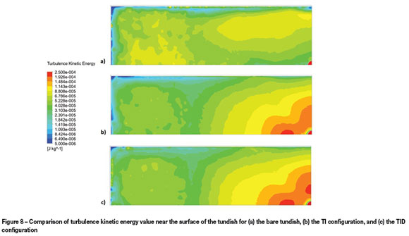
Visual comparison between the TI and TID cases in Figure 8 shows that the areas of higher turbulence expand very slightly with the addition of the holes and dams, with the average turbulence kinetic energy increasing from 6.01x10⁻⁵ m2/s2to 6.49x10⁻⁵m2/s2. The most likely explanation for this increase is that due to the increased strength of the circulation pattern at the top of the tundish for the TID case, more turbulence is generated when the flow rising from the inlet joins the flow from this circulation pattern.
Conclusions
A reduced-scale water model of a four-strand tundish was developed. The model was then used to perform RTD experiments to determine the flow behaviour of three different tundish configurations: a bare tundish with no flow control devices, a tundish with a turbulence inhibitor, and a tundish with both a turbulence inhibitor and a dam. A numerical model was also developed to simulate the behaviour of the water model to gain a clearer understanding of the physical model results. The numerical model was successfully validated against the physical model results.
A bare tundish was proven to be insufficient in providing good flow properties for tundish operation. Short minimum, peak, and mean residence times will limit inclusion removal, while a lack of strand similarity will reduce the quality of the product. High dead volumes will also prevent adequate mixing for homogenization and low plug flow volumes will limit inclusion removal. Both configurations with turbulence inhibitors were shown to decrease short-circuiting, decrease the dead volume, increase the plug flow volume, and increase the mean residence time. However, the addition of holes and dams to the configuration with only a turbulence inhibitor shows no clear improvement in flow properties. In fact, short-circuiting of the fluid passing through the holes decreases the minimum residence time and will allow larger inclusion to reach the mould. This short-circuiting could be prevented by increasing the height of the dams, but this approach resulted in a lower peak residence time and slightly larger dead volumes. It was determined that the surface-directed flow caused by the turbulence inhibitor more than doubles the maximum turbulence kinetic energy near the surface of the melt, increasing the potential for slag entrainment. The surface turbulence should therefore be considered during turbulence inhibitor design.
Acknowledgements
The authors wish to acknowledge NRF bursary funding for H. Cloete.
References
Ahuja, R. and Sahai, Y. 1986. Fluid flow and mixing of melt in steelmaking tundishes. Ironmaking and Steelmaking, vol. 13. pp. 241-247. [ Links ]
ANSYS. ANSYS FLUENT Theory Guide Version. 14. 2011. [ Links ]
Chattopadhyay, K., Isac, M., and Guthrie, R.I.L. 2010. Physical and mathematical modelling of steelmaking tundish operations: a review of the last decade (1999-2009). ISIJInternational, vol. 50, no. 3. pp. 331-348. [ Links ]
Craig, K.J., de Kock, D.J., Makgata, K.W., and de Wet, G.J. 2001. Design optimization of a single-strand continuous caster tundish using RTD data. ISIJ International, vol. 41, no.10. pp. 1194-1200. [ Links ]
De Kock, D.J., Craig, K.J., and Pretorius, C.A. 2003. Mathematical maximisation of the minimum residence time for a two-strand continuous caster. Ironmaking and Steelmaking, vol. 30, no. 3. pp. 229-234. [ Links ]
Jha, P.K., Rao, P.S., and Dewan, A. 2008. Effect of height and position of dams on inclusion removal in a six strand tundish. ISIJ International, vol. 48, no. 2. pp. 154-160. [ Links ]
Jha, P.K., Dash, S.K., and Kumar, S. 2001. Fluid flow and mixing in a six strand billet caster tundish: a parametric study. ISIJ International, vol. 41, no. 12. pp. 1437-1446. [ Links ]
Jha, P.K., Ranjan, R., Mondal, S.S., and Dash, S.K. 2003. Mixing in a tundish and a choice of turbulence model for its prediction. International Journal of Numerical Methodsfor Heat and Fluid Flow. vol. 8. p. 964 [ Links ]
Kumar, A., Mazumdar, D., and Koria, S.C. 2008. Modeling of fluid flow and residence time distribution in a four-strand tundish for enhancing inclusion removal. ISIJ International. vol. 48, no. 1. pp. 38-47. [ Links ]
Kumar, A., Koria, S.C., and Mazumdar, D. 2007. Basis for systematic hydrodynamic analysis of a multi-strand tundish. ISIJ International, vol. 47, no. 11. pp. 1618-1624. [ Links ]
Liu, S., Yang, X., Du, L., Lí, L., and Liu, C. 2008. Hydrodynamic and mathematical simulations of flow field and temperature profile in an asymmetrical t-type single-strand continuous casting tundish. ISIJ International, vol. 48, no. 12. pp. 1712-1721 [ Links ]
Mazumdar, D. and Guthrie, R.I.L. 1999. The physical and mathematical modelling of continuous casting tundish systems. ISIJ International, vol. 39, no. 6. pp. 524-547. [ Links ]
Miki, Y. and Thomas, B.G. 1999. Modeling of inclusion removal in a tundish. Metallurgical and Materials Transactions B, vol. 30. pp. 639-654. [ Links ]
Mishra, S.K., Jha, P.K., Sharma, S.C., and Ajmani, S.K. 2012. Effect of blockage of outlet nozzle on fluid flow and heat transfer in continuously cast multistrand billet caster tundish. Canadian Metallurgical Quarterly, vol. 51, no. 2. pp. 170-183. [ Links ]
Qu, T., Liu, C., and Jiang, M. 2012. Numerical simulation for effect of inlet cooling rate on fluid flow and temperature distribution in tundish. Journal of Iron and Steel Research International, vol. 19, no. 7. pp. 12-19. [ Links ]
Sahai, Y. and Emi, T. 1996. Criteria for water modeling of melt flow and inclusion removal in continuous casting tundishes. ISIJ International, vol. 36, no. 9. pp. 1166-1173. [ Links ]
Tripathi, A. and Ajmani, S.K. 2005. Numerical investigation of fluid flow phenomenon in a curved shape tundish of billet caster. ISIJ International, vol. 45, no. 11. pp. 1616-1625. [ Links ]
Tripathi, A. and Ajmani, S.K. 2011. Effect of shape and flow control devices on the fluid flow characteristics in three different industrial six strand billet caster tundish. ISIJ International, vol. 51, no. 10. pp. 1647-1656. [ Links ]
Zhong, L., Lí, B., Zhu, Y., Wang, R., Wang, W., and Zhang, X. 2007. Fluid flow in a four-strand bloom continuous casting tundish with different flow modifiers. ISIJ International, vol. 47, no. 1. pp. 88-94. [ Links ]
© The Southern African Institute of Mining and Metallurgy, 2015. ISSN2225-6253. This paper was first presented at the, Pyrometallurgical Modelling Principles and Practices, 4-5 August 2014, Emperors Palace Hotel Casino Convention Resort, Johannesburg.

