


Services on Demand
Article
 English (pdf)
 Article in xml format
 Article references
Indicators

Related links
-
 Cited by Google
 -
 Similars in Google
Share

 Permalink
Journal of the Southern African Institute of Mining and Metallurgy
On-line version ISSN 2411-9717
Print version ISSN 2225-6253
J. S. Afr. Inst. Min. Metall. vol.115 n.5 Johannesburg May. 2015
PYROMETALLURGICAL PAPERS
Sonic injection into a PGM Peirce-Smith converter: CFD modelling and industrial trials
D.K.ChibweI; G. AkdoganI; G.A. BezuidenhoutII; J.P.T. KapustaIII; S. BradshawI; J.J. EksteenI, IV
IProcess Engineering Department, University of Stellenbosch
IIProcess Division, Lonmin Western Platinum Limited, Marikana
III3BBA, Montréal, Canada
IVDepartment of Metallurgical Engineering, Curtin University, Perth, Australia
SYNOPSIS
Peirce-Smith converters (PSCs) are extensively used in the copper, nickel, and platinum group metals industries. The typical converting operation involves lateral purging of air into molten matte through a bank of tuyeres. This blowing operation occurs at low pressure from the blowers, resulting in a bubbling regime that is considered inefficient from both a process and an energy utilization perspective. Inherent drawbacks also include recurrent tuyere blockage, tuyere punching, and low oxygen efficiency. Western Platinum embarked on a full-scale industrial evaluation of generating a jetting regime by using sonic injection. Prior to industrial-scale tests, a numerical assessment to ascertain the feasibility of implementing sonic injection into a PSC was conducted. The work included flow characterization at high-pressure injection achieving sonic velocity at the tuyere exit. The 2D and 3D simulations of the three-phase system were carried out using the volume of fluid method together with the RKE turbulence model to account for the multiphase and turbulent nature of the flow. This paper discusses the key findings in understanding plume extension, velocity distribution, shear wall stress analysis, and phase distribution characteristics in the system. Plant trials are also discussed with reference to the commercial aspects of a full-scale implementation of sonic injection in the smelter.
Keywords: Peirce-Smith converter, sonic injection, CFD modelling
Introduction
Despite lengthy operational experience, understanding of the mode and principle of Peirce-Smith converter (PSC) operation has not changed significantly. Some modifications to the typical PSC have been adopted, one notable example being the Hoboken converter, which is fitted with a siphon that permits process gas collection without atmospheric dilution (Bustos et cel., 1995). Hoefele and Brimacombe (1979) allude to historical conservatism, rather than technological limitations, as the reasons for resistance to change.
Small versions of copper-nickel PSCs are used in platinum group metals (PGMs) smelters for removing Fe and S chemically associated with Cu-Ni mattes rich in PGMs. Lonmin plc operates a PGM PSC approximately one-third the working volume of a typical copper-nickel PSC. Due to the bubbling regime resulting from subsonic flow conditions currently employed in these operations, common problems are encountered. These include tuyere blockages (which necessitate frequent punching operations); high refractory wear in the tuyere region; substantial splattering and splashing, which generate significant amounts of reverts (Richards et cel., 1986; Wraith et cel., 1994; Kapusta, 2010) and also cause operational downtime with intermittent off-stack periods for cleaning the converter mouth and aisle; and reduced oxygen efficiency, which is attributed to the punching operation as a result of substantial air losses due to leakages, limiting the converter capacity or the reprocessing of reverts and dusts. These process inefficiencies are accompanied by energy inefficiencies or 'excess' power consumption related to punching machines, leaks at the tuyere body due to punching (wasted blower air), and unreacted injected air.
The conversion process occurs in a high-temperature environment in a refractory-lined steel shell vessel, which precludes visual observation and experimentation. In order to delineate critical process parameters, physical and numerical modelling techniques have been developed. Physical models with different liquids simulating matte and slag have been developed to study gas plume, splashing, mixing, phase distribution, and mass transfer phenomena (Hoefele and Brimacombe, 1979; Richards et cel., 1986; Chibwe, Akdogan, and Eksteen, 2011; Chibwe, Akdogan, Aldrich, and Eric, 2011; Chibwe, Akdogan, Aldrich, and Taskinen, 2011). Richards et al., (1986) concluded that the main cause of splashing was the development and intensification of slopping resulting from the manifestation of a uninodal wave. Their analysis showed that gas-liquid coupling increases with tuyere submergence depth, hence the reduction in splashing. For the small working volume PSC used in the PGM industry, tuyere submergence is shallow relative to that in Cu-Ni PSCs (Brimacombe et al., 1984). Any possible injection consideration in the small PSC should take this limitation into account.
PSC campaign life is dependent on the integrity and state of the refractory in the converter. Due to subsonic flow conditions, the refractory in the tuyere line has commonly been observed to deteriorate much faster than in the rest of the converter. Three mechanisms of refractory wear have been identified: chemical corrosion, thermal spalling, and mechanical wear (Gonzalez et al., 2007). Goni et al. (2006) quantitatively estimated that 35-65% of refractory wear in a PSC is due to chemical and thermomechanical processes. This type of refractory erosion is the result of a combination of gas dynamics in the proximity of the tuyere nozzle where high temperature gradients exist, and the punching operation, which generates mechanical shock.
Brimacombe et al. demonstrated at both the laboratory (Hoefele and Brimacombe, 1979; Brimacombe and Hoefele, 1980; Brimacombe et al., 1990) and plant scales (Brimacombe et al., 1984; Bustos et al., 1987) that sonic injection (jetting regime) into copper or nickel converters could reduce or eliminate the above-mentioned process and energy inefficiencies. In 1979, Hoefele and Brimacombe carried out the first experimental studies on sonic injection into a PSC using air-water, air-ZnCl2, and air-Hg systems coupled with plant trials. Pressure measurements in both laboratory experiments and plant trials showed that only the air-mercury system had the same bubble frequency as the plant, indicating the importance of the gas-liquid density ratios on the dynamics of submerged injection processes. Strikingly improved penetration of gas into liquid was observed at sonic conditions. Subsequent plant trials with straight-bore tuyeres designed for sonic flow were conducted at the ASARCO smelter in the USA (Brimacombe et al., 1984), the Toyo Smelter in Japan (Kimura et al., 1986), and the Noranda and INCO copper smelters in Canada (Bustos et al., 1987). The salient points from the above work were as follows: the horizontal penetration force is relatively low compared to the buoyancy force exerted by the bath; the stability of the tuyere accretions formed depends on converting cycle; and punchless operation is possible at higher injection pressure. Based on the understanding of accretion formation and stability, coupled with the process benefits of sonic injection, the Air Liquide Shrouded Injector (ALSI) technology was developed (Bustos et al., 1995). With ALSI technology, air oxygen enrichments between 30% and 40% have been achieved without detrimental refractory erosion. Commercial implementation of ALSI technology was inaugurated at the Falconbridge smelter in Canada (Bustos et al., 1999) and later notable applications included the Thai Copper Industries smelter (Kapusta et al., 2007).
Lonmin is interested in implementing such technology on a commercial scale. Prior to implementation, key process aspects needed to be evaluated, amongst them slopping, splashing and mixing characteristics, refractory integrity, and the possible extent of air penetration into the bath in these relatively small converters with shallow tuyere submergence. A realistic presentation of such a system needed to be developed in order to obtain conclusive interpretations for initial trials. Moreover, a rigorous system development satisfying the geometry and dynamic similarity was also needed.
For this purpose, characterization of the dynamics of the three-phase (air, matte, and slag) flow in the PSC used at Lonmin was conducted at high air pressure injection achieving sonic velocity at the tuyere tip by using CFD simulations. The 2D and 3D simulations of the three-phase system were carried out using the volume of fluid (VOF) and realizable turbulence models to account for the multiphase and turbulent nature of the flow respectively. These models were implemented using the commercial CFD numerical code FLUENT. The simulations from the current investigation revealed both qualitative and quantitative results of flow characteristics in the converter, which paved the way forward in planning the trials and selecting the converter to equip with sonic tuyeres. The full-scale plant trials have been successfully completed with promising results.
Numerical simulations
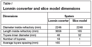
In this work, 2D and 3D simulations were carried out based on a slice model of the Lonmin PSC. Table I gives the dimensions of the actual converter and slice model.
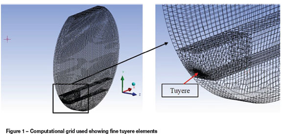
The computational domain was discretized into small control volumes for the calculations. Very fine meshes in the tuyere region were necessary to accurately capture the flow pattern. Domain decomposition was done in order to facilitate mesh multiple methods with local control for the creation of a conformal hybrid mesh as shown in Figure 1.
Modelling was done on an Intel® Core ™ i7 CPU with 3.46 GHz processor and 8.0 GB installed random access memory (RAM). The commercial CFD code ANSYS FLUENT, version 14.0, was used for the calculations on a high-power computing (HPC) cluster with an installed capacity of eight 2.83 GHz processors per node with 16 GB of RAM. In this paper, simulations conducted at midway through a typical blow will be presented, as this period accounts for more than 85% of the converting cycle time. In order to reduce the computational time during the simulations, the flow in the sonic tuyere was not included but simulated separately, and the flow conditions at the tuyere exit were taken as the inlet boundary condition of the computational domain. This value was calculated using the isentropic flow theory. Only two simulations were conducted with a 300 mm tuyere pipe coupled to the converter to visualize the development of air flow into the converter. A segregated solver with an implicit approach was used to calculate the pressure, velocity, turbulence, and density through solving unsteady and compressible flow conservation-governing equations, namely continuity, momentum, and energy. In order to account for the multiphase nature of the flow, the VOF model was used. The interfacial behaviour of air, matte, and slag was captured by this model using a compressive discretization scheme. This is accomplished by surface tracking of the phase interfaces in the system through solution of the VOF continuity equation. In the model, the different phases are treated numerically as interpenetrating continua, thus inevitably introducing the concept of phasic volume fraction where the volume fractions in each computational cell sum to unity. The effects of turbulence on the flow field inside the model were incorporated by using the realizable k-ε model, which offers improvements in the overall energy transfer. The flow conservation-governing equations, the VOF equation, and turbulence model equations were solved with FLUENT version 14.0. This package is a finite-volume solver using body-fitted computational grids. A coupled algorithm was used for pressure-velocity coupling. A compressive interface capturing scheme for arbitrary meshes (CICSAM) discretization was used to obtain face fluxes when the computational cell is near the interface using a piecewise-linear approach. This scheme was necessary due to the high viscosity ratios involved in this flow problem (ANSYS, 2011). A time step of 0.0001 seconds was used and found to be sufficient for maintenance of numerical convergence at every time step and stability. Convergence of the numerical solution was determined based on surface monitoring of integrated quantities of bulk flow velocity and turbulence and scaled residuals of continuity, x-, y-, z-velocities. The residuals of all quantities were set to 0.001, and the solution was considered converged when all the residuals were less than or equal to the set value.
Results and discussion
CFD modelling
From the numerical simulations conducted in this work, the computed plume extension for current (subsonic) and envisaged sonic operation are plotted in Figure 2. A dimensionless parameter (x/de) where x is the exit jet distance (in millimetres) and deis the exit tuyere diameter (in millimetres) was used to visualize the extent of the plume penetration into the converter.
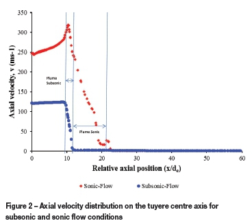
In Figure 2, the plume extension into the bath for subsonic and sonic conditions is indicated by 'Plume Sonic' and 'Plume Subsonic'. According to these results, plume sonic penetration into the bath is four times longer than that of plume subsonic. The extension of the plume region into the converter away from the tuyere exit area is essential as it provides extra volume for chemical reactions to take place. In their mass transfer studies of the PSC, Adjei and Richards (1991) concluded that the substantial part of the chemical reactions in the converter is likely to occur in the tuyere plume region.
Also, the simulations reveal that the bath circulatory velocity outside the plume region is approximately 0.27 m.s-1 for both flow conditions. These results are in consistent agreement with the assumption made by Bustos, Brimacombe, and Richards (1988) in their development of a mathematical model for accretions growth in PSCs for subsonic and sonic operations. Figure 3 shows the velocity vector distribution around the tuyere exit for both flow conditions. It can be observed that the sonic injection plume extends further into the bath, and with a higher velocity, than with subsonic operation. Lower velocity regions are evident further away from the plume.
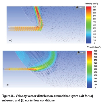
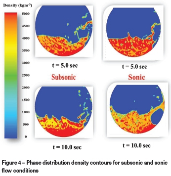
Figure 4 shows the phase density distribution for subsonic and sonic flow conditions. A high air volume region in front of the tuyeres can be seen for sonic flow conditions, compared with subsonic flow. This is consistent with the results shown in Figures 2 and 3. Due to the agitation in the regions in front of the tuyeres, a strong emulsification exists, resulting in high reaction rates in the zone. This is in agreement with the observations by Rosales et al. (1999) in their study of fluid dynamics in a Teniente converter.
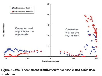
The effects of bath circulation and bath density on the walls of the converter were evaluated by calculating wall shear stress along the converter wall boundaries. Figure 5 shows the wall shear stress distribution for subsonic and sonic flow conditions. Near the tuyeres, for subsonic flow conditions a maximum wall shear stress of 200 Pa was obtained compared to 125 Pa for sonic flow. This suggests that sonic injection could reduce the refractory wear due to mechanical erosion around the tuyere region. At the wall opposite to the tuyeres line, the stress is higher for sonic injection due to the propagation of waves further from the tuyeres, which carry energy to the opposite sidewalls. This is desirable for achieving better mixing conditions in the converter, whereas with subsonic conditions energy is instantly dissipated just above the tuyeres as shown in Figure 3, which might lead to increased refractory erosion.
Plant trials
Plant trials were conducted to demonstrate the feasibility of high-pressure sonic injection technology into relatively small PSCs. Once the target total flow rate of compressed air into the converter and the number of sonic tuyeres had been finalized, sonic tuyeres were designed and dimensioned. All of the necessary equipment for the supply and control of the compressed air flow to the converter was also sourced in preparation for the trials. A new reline was installed and the punching machine was removed. The sonic tuyeres were installed using the same tuyere body as for normal operation. SCADA programming, alarms, and control set-points were then carefully evaluated and implemented to ensure the safe and controlled operation of the converter during the sonic injection trials.
The main purpose of high-pressure injection is the development of a different flow regime in the tuyere region through manipulation and designing of the blowing conditions and configuration. In this work, the dimensionless parameters - namely tuyere flow Mach number and injected air specific mixing power (εm) - were the main criteria for PSC manipulation and design for sonic injection. The injected air specific mixing power (εm) is given by:

where εbis the specific mixing power due to buoyancy and εkthe kinetic energy. The mathematical expressions are given in Equations [2] and [3]:
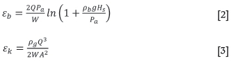
where
W is the effective bath weight (kg)
Q is the total gas flow rate (Nm3s-1)
Pais the atmospheric pressure (kPa)
A is the total tuyere cross-sectional area (m2)
pbis the bath density (kgm-3)
Hsis the injection submergence (m)
The PSC blowing conditions are given in Table II.
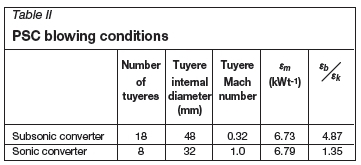
From Table II, it is evident that as the blowing conditions changes from subsonic to sonic regime, the Eb/εk ratio changes in such a manner that the flow is dominated by kinetic specific mixing power at sonic operation.
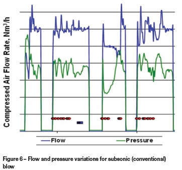
Before the sonic injection trials began it was found that the main characteristics of subsonic injection were the high variability of both the air flow rate and the injection pressure, as shown in Figure 6. This high variability is a direct consequence of the blocking accretions that form, resulting in lower flow and higher pressure, and the unplugging of the tuyeres by punching, resulting in a sudden higher flow and lower pressure.
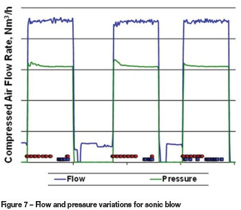
In contrast, as shown in Figure 7, the air flow rate during sonic injection is less variable compared to subsonic injection. A more stable air flow rate is one of the expected benefits of sonic injection. The flow rate curve shows a significantly reduced variability compared to the blow shown in Figure 6. Even more significant is the stability of the sonic injection pressure. The stability of both the flow rate and pressure demonstrated that the new operating strategy was successful. Controlled splashing was also accompanied by a stable flow rate and pressure of compressed air, as illustrated in Figure 7. Also, the maximum refractory wear rate ranged between 10.3 and 11.1 mm per blow, which corresponds to 37 to 40 blows per campaign, or a 34% reduction in refractory wear with sonic injection compared with conventional subsonic injection. These measurements of refractory wear, although conducted over a short period of time or a short number of blows, still provide an industrial validation of the theory that the accretions formed during sonic injection are indeed protective rather than disruptive.
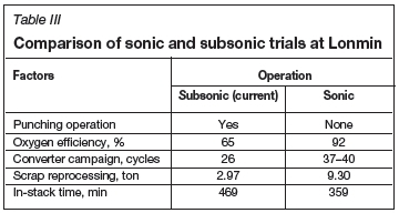
When operated in sonic mode, the converter capacity to reprocess reverts was found to increase by as much as 200% compared to that with the low-pressure bubbling regime, owing to the relatively higher oxygen efficiency. In summary, sonic injection offers significant flexibility for periods of high production of furnace matte - reducing the revert reprocessing rate to take full advantage of fast sonic blows -or for periods when a high reverts reprocessing capacity is needed. Table III highlights some of the benefits of using a sonic regime in the converter.
Conclusions
The CFD modelling formed part of an assessment to complement feasibility studies of implementing high-pressure sonic injection into relatively small Peirce-Smith converters (PSCs) used at Lonmin plc prior to the plant trials. The modelling work was carried out to characterize the fluid dynamics of three-phase (air, matte, and slag) fluid flow with high-pressure injection of air at sonic velocity. The modelling results provided a basis for further development of sonic injection into relatively small industrial PSCs, with the ultimate objective of reducing energy consumption, improving process efficiency, and increasing the throughput of the converting process. The results revealed that the plume extended into the bath approximately four times deeper at sonic flow conditions relative to subsonic flow conditions. Lower wall shear stress values for sonic flow conditions suggest that sonic injection could prolong the refractory life. Higher pressure injection gave rise to regions of high air volume in front of the tuyeres relative to low-pressure injection operation. With subsonic flow the injected gas ascended near the converter wall above the tuyeres for a significant period of time and thus a high refractory wear in the tuyere region would be expected relative to sonic injection. These findings showed that high-pressure injection into PGM PSCs converters is feasible.
Following the modelling exercise, sonic injection trials at one of Lonmin's converters were successfully completed. Punchless operation was achieved with sonic injection, with the capacity to reprocess much larger amounts of reverts than when operating in the conventional mode due to the higher oxygen efficiency in sonic mode. Sonic injection resulted in a lower refractory wear per blow or per ton of matte, leading to longer campaign cycles.
In summary, sonic injection offers significant flexibility for Lonmin's converting operation by allowing operators to adjust their practice for periods of high production of furnace matte - reducing the reverts reprocessing rate to take full advantage of fast sonic blows - or for periods when a high reverts reprocessing capacity is needed.
Acknowledgements
The authors acknowledge Lonmin Plc for the financing of this work, and express their gratitude to all personnel at Lonmin's converter aisle for their support and commitment to the success of the plant trials. Permission from BBA and Lonmin to publish this paper is also appreciated.
References
Adjei, E. and Richards, G.G. 1991. Physical modelling of mass transfer in a Peirce-Smith converter. Copper 91 - Cobre 91 International Conference IV, Ottawa, ON, Canada, 18-21 August 1991. Vol. IV. The Metallurgical Society of CIM. pp. 377-388. [ Links ]
Brimacombe, J.K., Meredith, S.E., and Lee, R.G.H., 1984. High-pressure injection of air into a Peirce-Smith copper converter. Metallurgical and Materials TransactionsB, vol. 15, no. 2. pp. 243-250. [ Links ]
Brimacombe, J.K. and Hoefele, E.O. 1980. Method of converting a bath of non-ferrous molten metal matte. US patent 4,238,228. [ Links ]
Bustos, A.A., Kapusta, J.P.T., Macnamara, B.R., and Coffin, M.R., 1999. High oxygen shrouded injection at Falconbridge. Copper 99 - Cobre 99 International Conference, Phoenix, AZ, 10-13 October 1999.. Vol. VI, Smelting Technology Developments, Process Modeling and Fundamentals. pp. 93-106. [ Links ]
Bustos, A.A., Brimacombe, J.K., and Richards, G.G. 1988. Accretion growth at the tuyeres of a Peirce-Smith copper converter. Canadian Metallurgical Quarterly, vol. 27, no. 1. pp. 7-21. [ Links ]
Bustos, A.A., Brimacombe, J.K., Richards, G.G., Vahed, A., and Pelletier, A. 1987. Development of punchless operation of Peirce-Smith converters. Copper 87 - Cobre 87 International Conference, Santiago, Chile. Vol. IV. Pyrometallurgy of Copper. Díaz, C., Landolt, C., and Luraschi, A. (eds). Alfabeta Impresores, Santiago. pp. 347-373. [ Links ]
Bustos, A A., Cardoen, M., and Janssens, B. 1995. High oxygen enrichment at UM-Hoboken converters. Copper 95 - Cobre 95International Conference. Vol IV. Pyrometallurgy of Copper. Chen, W.J., Díaz, C., Luraschi, A., and Mackey, P.J. (eds). The Metallurgical Society of CIM, Montreal, Canada. pp. 255-269. [ Links ]
Chibwe, D.K., Akdogan, G., Aldrich, C., and Eric, R.H. 2011. CFD modelling of global mixing parameters in a Peirce-Smith converter with comparison to physical modelling. Chemical Product and Process Modeling, vol. 6, no. 1. Article 22. [ Links ]
Chibwe, D.K., Akdogan, G., Aldrich, C., and Taskinen, P. 2011. Characterisation of phase distribution in a Peirce-Smith converter using water model experiments and numerical simulation. Mineral Processing and Extractive Metallurgy, vol. 120, no. 3. pp. 162-171. [ Links ]
Chibwe, D.K., Akdogan, G., and Eksteen, J.J. 2011. Solid-liquid mass transfer in a Peirce-Smith converter: a physical modelling study. Metallurgical and Mining Industry, vol. 3, no. 5. pp. 202-210. [ Links ]
Goni, C., Barbes, M.F., Bazan, V., Brandaleze, E., Parra, R., and Gonzalez, L.F.V. 2006. The mechanism of thermal spalling in the wear of the Peirce-Smith copper converter. Nippon Seramikkusu Kyokai Gakujutsu Ronbunshi, vol. 114, no. 8. pp. 672-675. [ Links ]
Gonzalez, C.A.R., Caley, W.F., and Drew, R.A.L., 2007. Copper matte penetration resistance of basic refractories. Metallurgical and Materials Transactions B, vol. 38, no. 2. pp. 167-174. [ Links ]
Hoefele, E.O. and Brimacombe, J.K., 1979. Flow regimes in submerged gas injection. Metallurgical and Materials Transactions B, vol. 10, no. 4. pp. 631-648. [ Links ]
Kapusta, J.P. 2010. Gas injection phenomena in converters - an update on buoyancy power and bath slopping. Proceedings of Cu2010, the Seventh International Copper - Cobre Conference. Hamburg, Germany. Vol. 2 -Pyrometallurgy I. The Society for Mining, Metallurgy, Resource and Environmental technology (GDMB). pp. 839-862. [ Links ]
Kapusta, J.P., Wachgama, N. and Pagador, R.U. 2007. Implementation of the Air Liquide Shrouded Injector (ALSI) technology at the Thai Copper industries Smelter. Proceedings of Cu2007, the Sixth International Copper-Cobre Conference, Toronto, ON. Vol. III (Book 1) - The Carlos Diaz Symposium on Pyrometallurgy Warner, A.E.M., Newman, C.J., Vahed, A., George, D.B., Mackey, P.J., and Warczok, A. (eds). The Metallurgical Society of CIM, Montreal, Canada. pp. 483-500. [ Links ]
Kimura, T., Tsuyuguchi, S., Ojima, Y., Mori, Y., and Ishii, Y. 1986. Protection of refractory by high-speed blowing in PS converter. 115th AIME Annual Meeting, New Orleans, LA, 7 March 1986. [ Links ]
Richards, G.G., Legeard, K.J., Bustos, A.A., Brimacombe, J.K., and Jorgensen, D, 1986. Bath slopping and splashing in the copper converter. The Reinhardt Schuhmann International Symposium on Innovative Technology and Reactor Design in Extraction Metallurgy, Colorado Springs, Co, 9-12 November 1986. Gaskell, D.R. (ed.). The Metallurgical Society of AIME, Warrendale, PA. pp. 385-402. [ Links ]
Rosales, M., Fuentes, R., Ruz, P., and Godoy, J. 1999. A fluid dynamic simulation of a Teniente converter. Copper 99-Cobre 99 International Conference, Phoenix, AZ, 10-13 October 1999. Vol. VI. Smelting Technology Developments, Process Modeling and Fundamentals. pp. 107-121. [ Links ]
Wraith, A.E., Harris, C.J., Mackey, P.J. and Levac, C. 1994. On factors affecting tuyere flow and splash in converters and bath smelting reactors. Proceedings of the European Metallurgical Conference 1994 (EMC'94), Vol. I. Society for Mining, Metallurgy, Resource and Environmental Technology (GDMB), Clausthal-Zellerfeld, Germany. pp. 50-78. [ Links ]
© The Southern African Institute of Mining and Metallurgy, 2015. ISSN2225-6253. This paper was first presented at the, Pyrometallurgical Modelling Principles and Practices, 4-5 August 2014, Emperors Palace Hotel Casino Convention Resort, Johannesburg.

