


Services on Demand
Article
 English (pdf)
 Article in xml format
 Article references
Indicators

Related links
-
 Cited by Google
 -
 Similars in Google
Share

 Permalink
Journal of the Southern African Institute of Mining and Metallurgy
On-line version ISSN 2411-9717
Print version ISSN 2225-6253
J. S. Afr. Inst. Min. Metall. vol.115 n.4 Johannesburg Apr. 2015
STUDENT EDITION
Critical investigation into the problems surrounding pillar holing operations
J.P. LabuschagneI; H. YilmazII; L. MpolokengIII
IUniversity of the Witwatersrand, Johannesburg, South Africa, Anglo American Platinum Bursary Holder/Trainee
IISchool of Mining Engineering, University of the Witwatersrand, Johannesburg, South Africa
IIIAnglo Development Centre, HRD Co-ordinator Mining
SYNOPSIS
An investigation into pillar cutting was carried out at a platinum mine on the western limb of the Bushveld Complex. The focus was on crush pillar design and implementation in order to ultimately improve the compliance percentage for pillar cutting. The major findings from the investigation suggest that the pillar cutting problem lies with the implementation of the design rather than the design itself. Observations of the practical issues underground that prevent good pillar cutting were made. After these issues had been identified, recommendations to rectify these problems and a few other issues identified during the investigation were provided. The recommendations are aimed at improving the pillar cutting compliance and reducing the likelihood of pillar bursts or pillar runs, which will ultimately create a safer mining environment.
Keywords: crush pillar, design, practical issues, implementation.
Introduction
The investigation was undertaken at a platinum mine on the western limb of the Bushveld Complex (BC), just outside the town of Rustenburg in South Africa's North West Province (Figure 1).
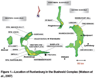
The mine, designated 'mine X', exploits the Merensky and UG2 reefs, which are currently the only reefs of economic importance.
The BC consists mainly of alternating layers of norite, pyroxenite, and anorthosite. The general stratigraphy of the Complex is shown in Figure 2.

The mine employs the conventional narrow-reef breast mining method. The workings are served by footwall waste rock development. The mine infrastructure consists of a main vertical downcast shaft that extends down to 15 level, 598 m below surface, and a decline that extends from 15 level down to 28 level at a depth of 927.1 m below surface. The Merensky Reef workings are accessed from the decline, whilst the UG2 workings are accessed from the vertical shaft. The support method consists of a regional pillar and chain crush pillar combination in order to support the hangingwall. The method of stoping and support is illustrated by Figure 3 (note the positions of the regional and chain crush (yielding) pillars.

The mine has a history of substandard pillar cutting practice. A few of the surrounding mines that have experienced pillar bursts due to substandard pillar cutting were taken as case studies in order to gauge the effect of noncompliance and identify the possible causes that can lead to a pillar burst.
The objectives of this investigation were to review the current design of crush pillars as practised at the mine, and to compare the current design with an alternative method. This further entailed the identification of the practical limitations experienced underground during pillar cutting. Finally, the recommendations to rectify the problems identified are provided.
Mine standards and compliance
The workings at mine X are divided into two sections, the Merensky section and the UG-2 section. The Merensky section is mined between 598 m and 927.1 m below surface, and the UG-2 section is mined down to 598 m below surface. The two sections have different support standards. Pillar cutting compliance refers to the percentage of crush pillars that are cut to the mine standards.
Merensky section
Crush pillars for the Merensky section are designed to be 4 m in length and 2.5 m wide, with a pillar height of approximately 1.1 m. The layout of a Merensky section panel can be seen in Figure 4.
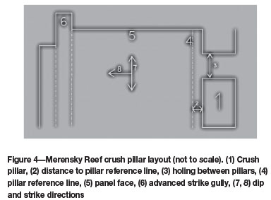
The position of the crush pillar (1) can be seen in relation to the pillar reference line (4), the holing between pillars (3), the panel face (5), the advanced strike gully (ASG) (6), the dip (8) and strike (7) direction. Note that the distance between the pillar reference line and the side of the crush pillar (2) should be 0.5 m.
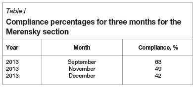
The pillar compliance percentages for 3 months were compiled and are shown in Table I.
UG2 section
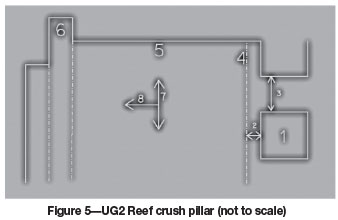
The crush pillars for the UG2 section are designed to be 3 m in length, 3 m wide, and approximately 1.1 m in height. Figure 5 illustrates the layout of a UG2 section panel. The explanation is the same as for the Merensky section (Figure 4), with the only difference being the crush pillar dimensions.
The compliance percentages for 3 months were compiled and are shown in Table II.
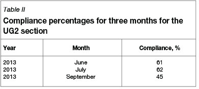
From Table I and Table II it can be seen that the compliance percentages are well below the acceptable standard of 80%, and this situation is indeed a cause for concern.
Case studies
Two case studies were conducted at mines that are in close vicinity to mine X and where pillar burst incidents had occurred. One involved a confirmed pillar burst at mine Y, and the other one involved a suspected pillar burst at mine Z. Both these incidents occurred during the project investigation. These case studies shed light on some important issues pertaining to the pillar cutting practice.
Mine Y confirmed pillar burst
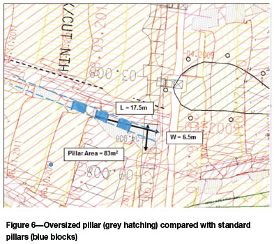
The pillar burst at mine Y generated a 2.9 magnitude seismic event. As a result, six employees were injured; fortunately, no fatalities occurred. This pillar burst was the result of an oversized pillar that was left inside the stope as mining progressed. According to the mine standards the pillar should have been roughly 3 m wide by 3 m in length. The actual size of the pillar was 17.5 m in length by 6.5 m in width, as illustrated in Figure 6. The blue blocks indicate the size of the crush pillars that should have been left according to the mine standards. As can be seen from Figure 6, the pillar that burst (hatched in grey) was unacceptably oversize.
According to Watson et al. (2007, 2010), pillars should crush close to the face (preferably within the first 7 m) under stiff loading conditions in order for controlled crushing to occur. Watson et al. (2010) also show that pillar bursts are likely to occur at 10 m to 14 m from the face under soft loading conditions. 'Stiff and 'soft' loading conditions are similar to the concept of loading done by the stiff and soft testing machines used in rock mechanics laboratories.
It can therefore be concluded that, referring to Figure 6, the smaller crush pillars that surrounded the oversize pillar all failed progressively under stiff loading conditions as the face advanced. The oversize pillar remained intact without crushing and moved well into the back area of the panel, where high stresses were accumulating in the pillar. The pillar eventually started crushing, and the excess strain energy that was stored in the foundation rocks of the pillar then released and caused violent failure.
Mine Z suspected pillar burst
Not much is known about the seismic event at mine Z, which occurred in December 2013, but it is suspected that the event can be attributed to a pillar burst. It is speculated that a large pillar with a width-to-height ratio greater than 10 was left behind in one of the panels. This was deemed acceptable, since the pillars with width-to-height ratios greater than 10 are known to be virtually indestructible (Ozbay et al., 1995). The problem suspected here was that the pillar consisted of two different rock types, one of which was weaker than the other. The rock types were separated along the vertical plane. The weaker part of the pillar started failing slowly, leaving only the stronger portion of the pillar intact. At that stage, the pillar was positioned well into the back areas as mining advanced, where soft loading conditions dominate. Owing to its reduced dimensions, the pillar was then within the bursting range. It is suspected that the pillar then burst, causing a seismic event.
Design and analysis
Crush pillars are designed in order to prevent a back-break of the hangingwall, while maximizing the percentage extraction. Crush pillars are generally used where mining takes place between 600 m and 1000m below surface (Jager and Ryder, 1999). The support layout used is a regional pillar and crush pillar combination as shown in Figure 3. This support layout allows for an increased extraction ratio while still ensuring stability of the hangingwall.
The first issue to focus on when designing a crush pillar is the residual strength of the pillar. The residual strength of a crush pillar is the strength that the pillar has after crushing has occurred. The residual strength must be sufficient to prevent a back break in order to be effective. Note that the crush pillars do not support the entire hangingwall strata to the surface. The regional pillars left on each side of the stope are responsible for the hangingwall support to surface. This means that crush pillars have to support only the tensile zone that exists between regional pillars.
According to Watson et al. (2010), in order to prevent a back break the residual strength of a crush pillar should be between 8 MPa and 13 MPa when pillar lines are spaced 30 m apart. For the purposes of this design, crush pillars are designed with a residual strength of 13 MPa.
The residual strength of a crush pillar can be determined by using a formula developed by Salamon (Watson et al., 2010):

where
h = pillar height (m)
w = pillar width (m)
Cb = the cohesion of the crushed rock material (MPa) (Watson et al., 2010, citing Salamon).
The Cb value was taken as 1.6 MPa, and h as 1 m. The pillar width corresponding to a residual strength magnitude of 13 MPa can then be calculated by trial-and-error and interpolation.
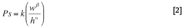
The next step is to find the pillar strength using the pillar width, which was obtained using Equation [1]. For design purposes, the pillars are taken to be square. There are two pillar strength formulae that are used in this design. Equation [2] refers to the slender pillar formula as currently used by mine X. Equation [2] is an adjusted version of the 1972 Hedley and Grant formula (Watson, 2010).
where
k = the design rock mass strength (DRMS) (MPa)
h = pillar height (m)
w = pillar width (m)
β = 0.75
α = 0.5 (Watson, 2010).
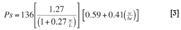
The other pillar strength formula that is used for comparison is explained by Watson et al. (2010) as follows (Equation [3]).
where
h and w are as defined above
L = pillar length (m)
he = [1 + 0.2692 (w/h)0.08)h.
Note that the 136 denotes a strength factor that should be altered for a different rock type. In the case of this design, 136 will be replaced by the DRMS that was established for the particular rock type.
The next step in the design process is to determine the average pillar stress (APS) for the specific scenario. This can be derived by using the tensile zone thickness that the crush pillars have to support.
The pillar factor of safety can then be determined in order to ensure that the proposed pillar will fail close to the face under stiff loading conditions. The pillar should then still provide sufficient support resistance based on the residual strength of the crushed pillar.
The results that were obtained showed a range of safety factors between 0.62 and 0.38, which ensure crushing under stiff loading conditions. Both the peak pillar strength equations [2] and [3] delivered similar results for the pillar strength. The pillar width-to-height ratio obtained was 2.15, which correlates well with the mine standards, where a width-to-height ratio range of 2.0-3.5 is acceptable.
The results also showed that as depth increases, the tensile zone thickness decreases, which means that larger inpanel pillars are more acceptable at shallower depths than at deeper levels.
The results obtained in this investigation suggest that pillar cutting is an application problem and not a design problem. For this reason, further investigations were carried out into the practical problems surrounding pillar cutting.
Practical problems in pillar cutting
Four practical problems with pillar holing operations were identified. These problems are discussed in the following sections.
Drilling discipline of rock drill operators
When the rock drill operators (RDOs) drill the stope face for production purposes, they drill in the direction of the ASG (strike direction). According to mine standards, holings between crush pillars have to be blasted after every 7 m face advance for the Merensky section, and after 6 m face advance for the UG2 section. This is due to the different pillar lengths (4 m in the Merensky section and 3 m in the UG2 section), with the pillar holings in both sections being 3 m wide. The problem occurs when it is time to blast the holings into the siding to create the crush pillars. The blast-holes are marked on the stope face and on the siding where the holing should be blasted. The RDOs then begin by drilling perpendicular holes into the stope face in the direction of the ASG. When it is time to turn 90° towards the siding of the panel in order to drill the blast-holes for the holing, RDOs tend to turn less than 90°. This results in a holing that is not blasted in the correct direction, but which is skewed in the direction of the face advance. Owing to this skewness, the holings tend to be longer than usual, hence the pillar width-to-height ratios are affected. The pillars that result from this poor drilling technique are longer than designed for. This in turn affects the effective pillar widths, and can hence lead to a pillar burst problem if not addressed.
Pillar reference line pegs lag behind panel advance
The pillar reference line has to be parallel to the ASG and a distance of 0.5 m from the side of the in-stope crush pillars. This reference line is painted onto the hangingwall of the stope in line with pegs that are installed by the surveyors. These pegs are normally installed regularly to ensure that the pillar line can be extended in a straight line and does not deviate from its intended direction. Offsets are taken from the pillar reference line to the siding of the panel, indicating where the pillars have to be situated. When the pegs for the pillar reference line lag the advancing panel, the line extension cannot be marked accurately. Generally this results in the pillar line deviating from its intended course, either towards the siding of the panel or towards the panel itself. When the reference line deviates towards the siding of the panel, undersize pillars can be expected. Conversely, if the line deviates towards the panel, then oversized pillars can be expected.
Substandard face marking
In some situations, the face marking is substandard due to the team leaders marking the face, and not the miner. As a result, the drill-holes are drilled in the wrong position or direction. Ultimately, the poor marking practice also affects the holing size and shape. Oversize or undersize pillars are inevitable, depending on the way the siding is marked. If the spacing between consecutive blast-holes is too large, then the pillars will tend to be undersize, and when the spacing is too small, the pillars tend to be oversize.
Rock removal (scraping) difficulties
The crush pillars are designed roughly 3 m x 3 m on both the Merensky and UG-2 reefs. This means that three blasts are required for a holing to be completed since the advance per blast is normally 1 m. This relates into a face advance of roughly 3 m during this three-blast period, since the face also advances roughly 1 m per blast. Therefore, in order to remove the broken rock from the blasted holing, the face scraper has to be moved back approximately 5-6 m from the face and rigged suitably at the holing after scraping the face. This takes extra time and effort, and the workers underground in some cases prefer not to lose this time in order to scrape the small quantity of rock, which eventually builds up in the holing.
Scraping the blasted rock in the holing usually causes a more serious problem - the sticks (elongates) become scraped out during this practice. The line of sticks needs to be constantly advanced as the face advances. The maximum distance that these sticks may be from the face is 4.3 m. When re-aligning the face scraper to remove the blasted rocks after the second and third blast of the holing, the scraper will have to be moved back. This means that it is highly likely to scrape out the sticks, which then have to be re-installed. In addition to the safety risks, the re-installation process takes time and wastes supplies, and hence costs are also raised.
The solutions applied underground to correct these kinds of problems are often crude in the sense that the solution creates another problem somewhere else. For example, the pillar holings could be blasted at an angle to try and avoid the problems associated with rock removal. This in turn could lead to incorrectly and unevenly sized pillars, which are in danger of bursting.
Conclusions
When attempting to design in-stope crush pillars, the determination of the tensile zone thickness becomes important in order to evaluate the demand required from crush pillars. As shown in this paper, the tensile zone thickness decreases with increasing depth. This is the premise upon which crush pillars can be implemented in stopes deeper than 600 m with fairly good results. The most important consideration when designing in-stope crush pillars is the residual strength that is required from the pillar in order to arrest a back break. This residual strength is matched to the required pillar width-to-height ratio. The peak pillar strength can then be computed for the width-to-height ratio required, and thus compared to the average pillar stress to determine whether the factor of safety is adequate. It should be noted that in crush pillar design, the safety factor should be less than 1.0, and optimally around 0.7. The low factor of safety is necessary in order to prevent a pillar burst, and to promote pillar crushing close to the stope face under stiff loading conditions.
Important considerations in crush pillar design were highlighted by the case studies of the pillar bursts at mine Y and mine Z. The problem at mine Y was that the pillars were cut with inconsistent dimensions, and one of the oversized pillars burst in the back area under softer loading conditions. The suspected pillar burst at mine Z showed that particular attention should be paid to avoid leaving pillars in situ that consist of more than one rock type.
The mine standards on crush pillars are found to compare well to the design results achieved in this investigation. However, the poor pillar cutting track record at mine X would lead to pillar burst problems in the near future in view of the incidents of crush pillar failures at the surrounding mines. Pillar cutting compliance therefore has to improve. During the investigation it was found that the problems regarding pillar cutting is not due to the design, but rather to implementation.
Recommendations
The following recommendations are offered to rectify the key issues identified surrounding pillar cutting that can cause pillar bursts and subsequent seismic events.
➤ The practical problems that were identified during this investigation have to be addressed to improve pillar cutting practice in order to avoid future crush pillar failures at the mine
➤ The tensile zone thickness increases as the mining depth decreases. This means that in-stope crush pillars at shallower depths carry higher loads than the deeper ones. The safety factor will therefore decrease as depth decreases if the crush pillar size remains the same. The crush pillar width-to-height ratio could be increased (so as to create a stronger pillar at shallower depths) to maintain a safety factor of about 0.7. It is therefore recommended that the width-to-height ratio of in-stope crush pillars is determined separately for each mining level. Mine management would then need to ensure that shift supervisors and mine overseers are aware of the different sizes of in-stope crush pillars on different levels
➤ Emphasis should be placed on cutting pillars consistently according to mine standards. Larger pillars should not be left in situ in order to compensate for smaller pillars left previously. The leaving of pillars with inconsistent dimensions increases the likelihood of premature pillar failures. The mine standards should rather be applied, even if the pillars were cut oversize or undersize previously
➤ Special care has to be taken to ensure that pillars are not cut in a position where they consist of more than one rock type. If this cannot be avoided, additional support such as thin spray-on liner or wire mesh and lacing could be applied to improve the crush pillar's yielding capability
➤ Pillars that have been identified as oversize pillars within bursting range should be de-stressed by means of drilling two parallel blast-holes into the pillar and blasting with a low powder factor in order to induce crushing. This preferably has to be done before the pillar moves more than 7 m away from the advancing face, where soft loading conditions will start to have an effect
➤ Drilling and blasting the holings from the top strike gully of the adjacent panel heaves the rock straight into the top gully of that panel, which solves the rock removal problems identified. Any rock leffinside the siding can be removed by a hand-shovel more easily down-dip
➤ The RDOs should be re-trained in order to emphasize that the pillar holings have to be blasted perpendicular to the face. Also, the RDOs should be made aware the dangers of leaving oversize or undersize pillars. This training should preferably be done by rock engineers
➤ Regular checks should be made to see whether the pegs are installed so that the pillar reference lines can be extended according to plan. More surveyors could be appointed to ensure that the pegs of the pillar reference lines do not fall behind the plan. Better communication between miners and the survey department should be encouraged so that pillar reference lines can be kept up to date
➤ Disciplinary measures should be taken against repeat offenders. This action can be justified by the panels that actually comply with the mine standards. A new bonus system could also be introduced in order to motivate employees to cut the in-stope crush pillars according to mine standards
➤ The substandard face marking problem can be overcome by either appointing more miners to share the work load or by training team leaders for face marking. Miners can then focus on marking the pillar holings since the team leaders can mark the face. This reduces the work load on the miner and hence leaves no excuses for substandard marking of the face or holing
➤ Using a burn cut blasting pattern with 3 m long holes can be trialled in order to see whether it can solve the rock removal problems. If this succeeds, then a holing can be blasted in a single blast, and no rock removal problems will be experienced.
References
Jager, A.J. and Ryder, J.A. 1999. A Handbook on Rock Engineering Practice for Tabular Hard Rock Mines. Safety in Mines Research Advisory Committee, Johannesburg. [ Links ]
Ozbay, M.U., Ryder, J.A., and Jager, A.J. 1995. The design of pillar systems as practised in shallow hard-rock tabular mines in South Africa. Journal of the South African Institute of Mining and Metallurgy, vol. 95. pp.7-18. [ Links ]
Watson, B.P. 2010. Rock behaviour of the Bushveld Merensky Reef and the design of crush pillars. Faculty of Engineering and the Built Environment, University of the Witwatersrand, Johannesburg. pp.201-207 [ Links ]
Watson, B.P., Kuijpers, J.S., and Stacey, T.R. 2010. Design of Merensky Reef crush pillars. Journal of the Southern African Institute of Mining and Metallurgy, vol. 110. pp. 581-591. [ Links ]
Watson, B.P., Roberts, MK, Nkwana, M.M., Kuijpers, J., and van Aswegen, L. 2007. The stress-strain behaviour of in-stope pillars in the Bushveld platinum deposits in South Africa. Journal of the Southern African Institute of Mining and Metallurgy, vol. 105. pp. 187-194. [ Links ]
Paper written on project work carried out in partial fulfilment of BSc. Eng. (Mining Engineering)

